Siemens SCD 1297 Operating Instructions Manual
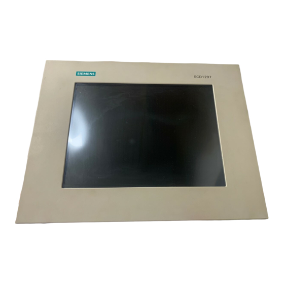
High resolution 31 cm/12" lcd-monitor scd 1297 series
Hide thumbs
Also See for SCD 1297:
- Operating instructions manual (44 pages) ,
- Operating instructions manual (19 pages)
Table of Contents
Advertisement
High Resolution 31 cm/12" LCD-Monitor SCD 1297
Operating Instructions
SCD 1297-C/CT (1) (Chassis)
6GF6240-3MA (-3MB with Touch)
SCD 1297-E/ET/ETH/ETC/ETB (1) (Mountable)
6GF6240-4MA (-4MB with Touch)
6GF6244-4MB/ 6GF6240-4MC/6GF6242-4MB
SCD 1297-R/RT (1)(Rack 19")
6AV8100-0CA00.0AA1/6AV8100-0CB00-0AA1)
6GF6240-6MA01 (-6MB01 with Touch)
© © © © Copyright Siemens AG
LCD-Monitor SCD1297
DOC-No.: B3 0071D1.DOC
Page 1 / 19
Advertisement
Table of Contents

Related Manuals for Siemens SCD 1297


Summary of Contents for Siemens SCD 1297
- Page 1 High Resolution 31 cm/12" LCD-Monitor SCD 1297 Operating Instructions SCD 1297-C/CT (1) (Chassis) 6GF6240-3MA (-3MB with Touch) SCD 1297-E/ET/ETH/ETC/ETB (1) (Mountable) 6GF6240-4MA (-4MB with Touch) 6GF6244-4MB/ 6GF6240-4MC/6GF6242-4MB SCD 1297-R/RT (1)(Rack 19") 6AV8100-0CA00.0AA1/6AV8100-0CB00-0AA1) 6GF6240-6MA01 (-6MB01 with Touch) © © © © Copyright Siemens AG LCD-Monitor SCD1297 DOC-No.: B3 0071D1.DOC...
- Page 2 part this document reproduced or transmitted without express permission. Violations will result in prosecution. All rights reserved. 2001 All rights reserved ˙t (A ) LCD-Monitor SCD1297 DOC-No.: B3 0071D1.DOC Page 2 / 19...
-
Page 3: Table Of Contents
EU Declaration of Conformity on EMC................19 Figures Figure 1: Dimensions of the SCD 1297-C/CT..................8 Figure 2: Dimensions of the SCD 1297-E/ET ..................9 Figure 3: Dimensions of the SCD 1297-R/RT..................9 Figure 4: VGA Interface........................11 Figure 5: Location of the operation and alignment controls ............... 13 LCD-Monitor SCD1297 DOC-No.: B3 0071D1.DOC... -
Page 4: Overview
At the press of a button, the monitor performs these alignments automatically. The SCD 1297 is equipped with an active 12.1” TFT display module with a maximum resolution of 800x600 pixels. The integrated power management system VESA DPMS, allows a significant reduction in power consumption when the synchronisation signal from the computer has been switched off, compared with that under “normal”... -
Page 5: Layout Of This Handbook
In detail, the chapters are arranged as follows: • • • • Chapter 1 Introduction This chapter provides a brief description of the SCD 1297, including its properties, application areas and special features. • • • • Chapter 2 Installation This chapter is mainly concerned with preparing the LCD-monitor for use, its installation and cabling. -
Page 6: Warnings And Safety Notes
1.2 Warnings and Safety Notes Transport The LCD-monitor should only be transported in its original packaging to ensure it will be protected against shocks and rough handling. Setting up When installing the monitor, it should be noted whether any moisture (condensation) has entered the unit during transport or storage. -
Page 7: Instructions For Handling Assemblies Susceptible To Electrostatic Shock
Susceptible Electrostatic Shock Most of the assemblies within the SCD 1297 LCD-monitor contain components which can be destroyed by electrostatic voltages. It is also possible for the assemblies to be damaged in such a way that total failure does not occur. -
Page 8: Installing The Lcd-Monitor
Two fixing brackets can be used to mount the SCD 1297-C(CT) behind a front plate. The SCD 1297-E(ET) is delivered together with a front plate. It has a sealing band all the way round. When mounting the front plate, care must be taken to ensure that the O-ring remains in its groove otherwise the seal may not be tight. -
Page 9: Figure 2: Dimensions Of The Scd 1297-E/Et
M3x10 Figure 2: Dimensions of the SCD 1297-E/ET S IEMENS ACT IVE AREA 246x184.5 Figure 3: Dimensions of the SCD 1297-R/RT LCD-Monitor SCD1297 DOC-No.: B3 0071D1.DOC Page 9 / 19... -
Page 10: Installation Of The Ac/Dc-Power Supply Unit Or 24V-Dc/Dc-Converter
Thermal Problems In order that the LCD-monitor maintains an optimum operating temperature while in use, air must be allowed to circulate freely around the SCD 1297 enclosure. It is particularly important that the rear of the system is kept free. -
Page 11: Figure 4: Vga Interface
A high-quality 75-ohm coaxial cable must be used for the VGA-signals. Low quality cables can result in interference and shadowing on the display. VGA-Interface The VGA interface is a standard 15-pin male HD-D-type connector. Figure 4: VGA Interface Signal Video input RED Video input GREEN Video input BLUE Not used... -
Page 12: Electrical Installation
Power Supply Power is supplied to the SCD 1297 via a standard power connector on the rear of the unit. Name Description Power supply ground GND +12V Power supply +12VDC 2.4 Electrical Installation Before connecting the SCD 1297 to the power supply, a check should be carried out as to whether the VGA connector is plugged in properly and that the screws are tightened. -
Page 13: Operation And Alignment
3 Operation and Alignment This chapter contains a description of all the operating and alignment functions. 3.1 Location of the Operation and Alignment Controls All the controls are accessible from the rear of the unit. Their exact position in shown in Figure 1 on page 32. -
Page 14: Using And Adjusting The Converter
3.2 Using and Adjusting the Converter Since there are no standards for video output signals from VGA cards, the first time the unit is switched on it will automatically adjust itself to the graphic card currently being used. 3.2.1 OSD-Menu The „On Screen Display“... -
Page 15: Quick-Osd-Menu-Functions
3.2.2. Quick-OSD-Menu-Functions Following adjustments can do via the Quick-OSD-menu: Brightnes Contrast Auto adjust Invoke via key <SET> Function Adjustment/value Description Contrast Range: 0 to 100 Contrast adjustment +>/<-> via key < Brightness Range: 0 to 100 Brightness adjustment +>/<-> via key < Invoke via key <+>... -
Page 16: Osd-Menu-Function
3.2.3. OSD-Menu-Function Invoke via key <MENUE> Main menu Function Adjust function / value / range Description Picture 1 Brightness setting range: adjust brightness 0 to 100 through key (+/-) Contrast setting range: adjust contrast 0 to 100 through key (+/-) change contrast between dark and light colors H Position setting range:... - Page 17 Main menu Function Adjust function / value / range Description Display Power Management System (DPMS) on or off Option 2 DPMS ON – OFF If DMPS activated, the monitor is turn off (backlight) when a synch signal is left. The screen is dark. Source scan OFF –...
-
Page 18: Technical Data
4 Technical Data 4.1 Display Module Type Colour active TFT-LCD Diagonal 30.8 cm (12.1") Display area (WxH) 246 x 184.5 mm² Resolution 800 x 600 pixels Pitch 0.33 x 0.33 mm² Colours 262144 Backlight 2xCCFT (Cold Cathode Fluorescent Tube) Brightness (typical) approx. -
Page 19: Enclosure
Sync on green Composite Sync H-Frequency 30 to 97 kHz V-Frequency 50 to 100 Hz** 4.7 EU Declaration of Conformity on EMC Product LCD-Monitor SCD 1297 Test foundations EU framework guidelines No. 89/336/EWG No. 92/031/EWG No. 73/23/EWG No. 93/68/EWG Harmonised...