Siemens Milltronics BW500 Operating Instructions Manual
Integrators
Hide thumbs
Also See for Milltronics BW500:
- Operating lnstructions (170 pages) ,
- Instruction manual (154 pages)
Table of Contents
Advertisement
Quick Links
Bufferzone
The image must not touch with the Bufferzone.
Background coolgray 20%, without history
8 mm
Integrators
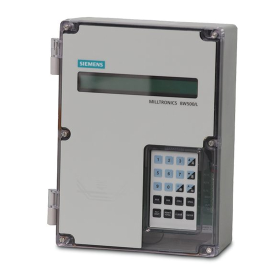
Milltronics BW500 and BW500/L
8 mm
Operating Instructions
A text area at the top is (big bar) 2-Spaltig, so the text extends upwards!
Then adjust the transparent beams according to and while holding the
8 mm distance from text.
I think this means that, if you need to add more lines of text, extend the big
bar upwards, while maintaining the proper distance from the text.
The lower pane (smal bar, Dokuklasse) must be only single-column!
Title page without bleed
in RGB
Find any font sizes for the text fields in the
Panel "Paragraph styles"!
Image should come behind the bar so that
the transparency comes to the fore.
Do not change the transparency of the bar!
Siemens Serif OT, Semibold, 36/30/26 PT, weiss
Absatzformat: 01 System 36/30/26 pt
Siemens Sans OT, Bold, 18/15/13 PT, weiss
Absatzformat: 02 Produkt 18/15/13 pt
Siemens Sans OT, Bold, 13/11 PT, weiss
Absatzformat: 03 Titel 13/11 pt
Siemens Sans OT, Bold, 13 PT, weiss
Absatzformat: 04 Dokuklasse 13 pt
Natural Blue dark CoolGray 100%
Edition
Siemens Sans OT, Bold, 11/7,5 pt, weiss
Absatzformat: 05 Ausgabe 11/7,5 pt
Siemens Sans OT, Bold, 13 PT, schwarz
Absatzformat: 06 SectorClaim 13 pt
12/2016
Advertisement
Table of Contents

Related Manuals for Siemens Milltronics BW500


Summary of Contents for Siemens Milltronics BW500
- Page 1 Background coolgray 20%, without history Image should come behind the bar so that the transparency comes to the fore. Do not change the transparency of the bar! Siemens Serif OT, Semibold, 36/30/26 PT, weiss Absatzformat: 01 System 36/30/26 pt 8 mm Integrators...
- Page 2 • For a selection of Siemens level measurement manuals, go to: Level Measurement. www. siemens.com/processautomation. Select Products & Systems, then under Process Instrumentation, select Manual archives can be found on the Support page by product family. • For a selection of Siemens weighing manuals, go to: Weighing and Batching Systems.
- Page 3 ___________________ Safety Notes okjlkjlj ___________________ The Manual ___________________ Milltronics BW500 and BW500/L Milltronics ___________________ Specifications Integrators ___________________ Installation BW500 and BW500/L ___________________ Start Up ___________________ Operating Instructions Recalibration ___________________ Operation ___________________ PID Control ___________________ Batching ___________________ Communications ___________________ Parameters ___________________...
- Page 4 Note the following: WARNING Siemens products may only be used for the applications described in the catalog and in the relevant technical documentation. If products and components from other manufacturers are used, these must be recommended or approved by Siemens. Proper transport, storage, installation, assembly, commissioning, operation and maintenance are required to ensure that the products operate safely and without any problems.
-
Page 5: Table Of Contents
Table of contents Safety Notes ............................11 The Manual ............................13 Milltronics BW500 and BW500/L ......................15 Specifications ............................17 Installation ............................21 Dimensions ..........................21 Layout ............................. 23 Optional Plug-ins ........................25 5.3.1 SmartLinx Module ........................25 5.3.2 mA I/O board ........................... 25 5.3.3... - Page 6 Table of contents 5.16 Installing/replacing the back-up battery ................. 44 Start Up ..............................47 Keypad ........................... 47 Program Mode ........................48 6.2.1 Program Mode Display ......................48 6.2.2 To enter PROGRAM mode ....................49 6.2.3 RUN Mode ..........................51 Initial Start Up ......................... 51 6.3.1 Power Up ..........................
- Page 7 Table of contents Speed Sensing ........................97 Differential Speed Detection ....................98 Moisture Compensation ......................98 Incline compensation ......................99 Modes of Operation ......................100 Damping ..........................100 mA I/O (0/4-20 mA) ....................... 101 Relay Output ......................... 102 8.10 Totalization ..........................103 8.10.1 Internal Totalizer ........................
- Page 8 Table of contents 11.3.5 P774 Data bits........................129 11.3.6 P775 Stop bits ........................129 11.3.7 P778 Modem attached ......................129 11.3.8 P779 Modem idle time ......................130 11.3.9 P780 RS-232 Transmission interval ..................130 11.3.10 P781 Data message ......................131 11.3.11 P799 Communications Control ....................
- Page 9 Table of contents 12.3.4 P212 mA Output Minimum ....................162 12.3.5 P213 mA Output Maximum ....................162 12.3.6 P214 4 mA Output Trim ......................162 12.3.7 P215 20 mA Output Trim ...................... 162 12.3.8 P220 mA Output Damping ....................162 12.3.9 P250 mA input range ......................
- Page 10 Table of contents 12.8 Batch Control (P560 – P568) ....................176 12.8.1 P560 Batch Mode Control ....................176 12.8.2 P564 Batch Setpoint ......................177 12.8.3 P566 Batch Pre-Warn ......................177 12.8.4 P567 Batch Pre-Warn Setpoint .................... 177 12.8.5 P568 Batch Pre-Act ......................177 12.8.6 P569 Manual Batch Pre-Act Amount ...................
- Page 11 Table of contents 12.13.3 P911 mA Output Test ......................190 12.13.4 P914 mA Input Value ......................190 12.13.5 P918 Speed Input Frequency ....................190 12.13.6 P931 Running Totalizer ......................190 12.13.7 P940 Load Cell mV Signal Test .................... 191 12.13.8 P943 Load Cell A/D Reference .....................
- Page 12 Table of contents BW500 and BW500/L Operating Instructions, 12/2016, A5E33482052-AD...
-
Page 13: Safety Notes
Safety Notes Special attention must be paid to warnings and notes. WARNING WARNING It means that failure to observe the necessary precautions can result in death, serious injury, and/or considerable material damage. Note It means important information about the product or that part of the operating manual. BW500 and BW500/L Operating Instructions, 12/2016, A5E33482052-AD... - Page 14 Safety Notes BW500 and BW500/L Operating Instructions, 12/2016, A5E33482052-AD...
-
Page 15: The Manual
The Manual Note • The Milltronics BW500 and BW500/L are to be used only in the manner outlined in this instruction manual. • These products are intended for use in industrial areas. Operation of this equipment in a residential area may cause interference to several frequency based communications. - Page 16 The Manual BW500 and BW500/L Operating Instructions, 12/2016, A5E33482052-AD...
-
Page 17: Milltronics Bw500 And Bw500/L
Milltronics BW500/L The Milltronics BW500/L is an integrator for use in basic belt scale or weighbelt applications. The speed and load signals from the conveyor and scale, respectively, are processed to derive rate of material flow, and totalization. The BW500/L does not include the advanced feature set for control. - Page 18 Milltronics BW500 and BW500/L Popular Windows and Industrial communications ● Two RS232 ports ● One RS485 port Individual port configuration for ● Dolphin Plus ● Modbus ASCII ● Modbus RTU ● Printer ● SmartLinx compatible Controls and operation functions BW500...
-
Page 19: Specifications
DC version • Fuse FU2 = 3.75A Resettable (not user replaceable) Application Compatible with Siemens belt scales or equivalent 1, • 2, 4, or 6 load cell scales (1 or 2 load cell scales for BW500/L) Compatible with LVDT equipped scales, with use of •... - Page 20 Specifications Inputs Load cell 0 ... 45 mV DC per load cell Speed sensor Pulse train 0 V low, 5 V high (TTL setting) or 10 ... 24 V high (HTL setting), 1 ... 3000 Hz or open collector NPN switch or relay dry contact Auto zero Dry contact from external device...
- Page 21 BW500/L. Options Siemens MD-36/36A/256 or 2000A, RBSS, TASS, Speed Sensor • WS100, or WS300, or compatible Siemens Windows based software interface (refer to as- Dolphin Plus • sociated product documentation) protocol specific modules for interface with popular indus- SmartLinx Modules •...
- Page 22 Specifications Options Isolated 24 V DC at 50 mA, short circuit protected Output supply • LVDT interface card For interface with LVDT based scales Not available with BW500/L. Weight 2.6 kg (5.7 lb) Approvals BW500 BW500/L , CSA US/C, FM, RCM, GOST ✓...
-
Page 23: Installation
Installation Note • Installation shall only be performed by qualified personnel and in accordance with local governing regulations. • This product is susceptible to electrostatic shock. Follow proper grounding procedures. Dimensions Note Nonmetallic enclosure does not provide grounding between connections. Use grounding type bushings and jumpers. - Page 24 Installation 5.1 Dimensions ① Lid screws (6 pieces) ② Customer mounting screw ③ Enclosure ④ ⑤ Mounting hole (4 places) ⑥ Conduit entry area. Recommend drilling the enclosure with a hole saw and the use of suitable cable glands to maintain ingress rating. BW500 and BW500/L Operating Instructions, 12/2016, A5E33482052-AD...
-
Page 25: Layout
Installation 5.2 Layout Layout ① Battery, memory back up ② Port 3 (RJ-11) ③ Fuse FU3 ④ Optional LVDT conditioner card ⑤ Optional Analog I/O board ⑥ Certification switch ⑦ Optional SmartLinx module Applicable for trade approvals. Not available for BW500/L. To reduce communication interference, route SmartLinx cable along right side. - Page 26 Installation 5.2 Layout WARNING • All field wiring must have insulation suitable for at least 250 V. • DC input terminals shall be supplied from a source providing electrical isolation between the input and output, in order to meet applicable safety requirements of IEC 61010-1. •...
-
Page 27: Optional Plug-Ins
Optional Plug-ins 5.3.1 SmartLinx Module BW500 and BW500/L is software/hardware ready to accept the optional Siemens SmartLinx communications module that provides an interface to one of several popular industrial communications systems. BW500 and BW500/L may be shipped to you without a SmartLinx module, for installation at a later date. -
Page 28: Lvdt Conditioner Card
Installation 5.3 Optional Plug-ins BW500 may be shipped to you without an mA I/O board, for installation at a later date. If you are ready to install your mA I/O board, please follow the instructions as outlined. Installation 1. Isolate power and voltages applied to the BW500 2. -
Page 29: Optional Components And Their Locations
Installation 5.4 Interconnection 5.3.4 Optional Components and their Locations ① SmartLinx ② Route SmartLinx cable along right hand wall ③ LVDT conditioner card ④ mA I/O board Interconnection Note • Wiring may be run via common conduit. However, these may not be run in the same conduit as high voltage contact or power wiring. -
Page 30: System Diagram
⑨ Optional fieldbus connection (SmartLinx card required) ⑩ Communication ports can be configured for Siemens Milltronics Dolphin Plus, print data, or Modbus ASCII or RTU protocol ⑪ Communication ports can be configured for Siemens Milltronics Dolphin Plus, print data, or Modbus ASCII or RTU protocol ⑫... -
Page 31: Scale - One Load Cell
Customer junction box ② Load cell excitation ③ Load cell inputs Note Color code for load cells used on Siemens weighfeeders may be different than shown. Please refer to the weighfeeder wiring diagram. BW500 and BW500/L Operating Instructions, 12/2016, A5E33482052-AD... -
Page 32: Scale - Two Load Cells
2. Run additional conductors from: BW500 and BW500/L terminal 12 to scale 'red' BW500 and BW500/L terminal 13 to scale 'blk' If the load cell wiring colors vary from those shown, or if extra wires are provided, consult Siemens. 5.4.3 Scale - Two Load Cells ①... - Page 33 5.4 Interconnection Note Color code for load cells used on Siemens weighfeeders may be different than shown. Please refer to the weighfeeder wiring diagram. Where separation between the BW500 and BW500/L and belt scale exceeds 150 m (500 ft.), or legal for trade certification: 1.
-
Page 34: Scale - Four Load Cells
Installation 5.4 Interconnection 5.4.4 Scale - Four Load Cells ① Customer junction box ② Integrator ③ Load cell excitation ④ Load cell inputs Where separation between the BW500 and belt scale exceeds 150 m (500 ft), or legal for trade certification: 1. -
Page 35: Scale - Six Load Cells
Installation 5.4 Interconnection If the load cell wiring colours vary from those shown, or if extra wires are provided, consult Siemens. Note Not available with the BW500/L. 5.4.5 Scale - Six Load Cells ① Customer junction box ② Integrator ③... -
Page 36: Scale - Lvdt
5.4.6 Scale - LVDT ① Siemens Milltronics LVDT Conditioner ② Load cell excitation ③ Siemens Milltronics BW500 and BW500/L ④ Load cell inputs ⑤ Maximum cable run LVDT to Conditioner 300 m (1000 ft) ⑥ Belt scale with LVDT The LVDT Conditioner Card can be mounted on the BW500 or BW500/L Motherboard, or in a remotely located enclosure. -
Page 37: Speed
Installation 5.5 Speed ♦ Cable shields must connect to ground only through the BW500 or BW500/L Motherboard (TB15). They should not be grounded to the LVDT Conditioner Card enclosure or any other location. * Where separation between the BW500 or BW500/L and LVDT conditioner exceeds 150 m (500 ft): 1. -
Page 38: Main Speed Sensor
16 / 17 will also serve as a suitable speed signal. If a speed sensor other than the models shown is supplied, consult with Siemens for details. For the Main Speed Sensor input, switch SW3 should be set to "HTL" for use with speed sensors providing 12V output logic, open-collector NPN outputs or dry contacts. -
Page 39: Auxiliary Speed Sensor
As per the "HTL" setting for the Main Speed Sensor input, an internal pullup of 12 V through a 3.3 kohm resistor is supplied, with a switching threshold of 5.5 V (nom.) and +/- 1 V hysteresis. If a speed sensor other than the models shown is supplied, consult with Siemens. Note Auxiliary speed sensor not available for BW500/L. -
Page 40: Auxiliary Inputs
Installation 5.6 Auxiliary Inputs Auxiliary Inputs Customer dry contacts, or open collector transistor output supplied as required. Refer to P270 (Page 165) for programming details. Auto Zero Prefeed activated dry contact. Refer to Auto Zero (Page 76). BW500 and BW500/L Operating Instructions, 12/2016, A5E33482052-AD... -
Page 41: Rs232 Port 1
Installation 5.8 RS232 Port 1 RS232 Port 1 5.8.1 Printers ① Printer ② Receive ③ Common 5.8.2 Computers and Modems For connection to a PC compatible computer or modem, using no flow control, typical configurations are: BW500 and BW500/L Operating Instructions, 12/2016, A5E33482052-AD... -
Page 42: Remote Totalizer
Installation 5.9 Remote Totalizer Remote Totalizer ① Supply, 30 V max, Remote totalizer 1 ② Supply, 240 V max, Remote totalizer 2 Note External power supply not required on all totalizer models. 5.10 mA Output 1 to customer instrumentation, isolated mA out- put, 750 Ω... -
Page 43: Rs485 Port 2
Installation 5.12 RS485 Port 2 5.12 RS485 Port 2 5.12.1 Daisy Chain ① Customer device 5.12.2 Terminal Device ① Customer device 5.13 RS232 Port 3 Note Jumper pins 4-6 and 7-8 on the DB9 connector when using hardware flow control. Otherwise, leave them open. -
Page 44: Power Connections
Installation 5.14 Power Connections 5.14 Power Connections The BW500 is available in AC or DC power models. Note AC power connections 1. The equipment must be protected by a 15 A fuse or a circuit breaker in the building installation. 2. -
Page 45: Ma I/O Board Connections
Installation 5.15 mA I/O Board Connections 5.15 mA I/O Board Connections ① Auxiliary supply output, isolated 24 V DC at 50 mA, short circuit protected ② From customer instrumentation, isolated mA input, 200 Ω ③ From customer instrumentation, isolated mA input, 200 Ω ④... -
Page 46: Installing/Replacing The Back-Up Battery
Installation 5.16 Installing/replacing the back-up battery 5.16 Installing/replacing the back-up battery The battery (see Specifications (Page 17)) should be replaced every 5 years to ensure back up during lengthy power outages. An on board capacitor provides 20 minutes of charge to preserve the memory while the battery is being changed. - Page 47 Installation 5.16 Installing/replacing the back-up battery BW500 and BW500/L Operating Instructions, 12/2016, A5E33482052-AD...
-
Page 49: Start Up
Start Up Note For successful start up, ensure that all related system components, such as the belt scale and speed sensor, are properly installed and connected. BW500 and BW500/L operates under two modes: RUN and PROGRAM. On initial powerup, the unit starts in the PROGRAM mode. -
Page 50: Program Mode
Start Up 6.2 Program Mode Function PROGRAM mode RUN mode In view mode: scrolls through changes PID local setpoint parameter list values decimal key prints minus key switches PID between auto and manual mode opens RUN mode opens parameter direct entry opens PROGRAM mode initiates calibration initiates calibration... -
Page 51: To Enter Program Mode
Start Up 6.2 Program Mode 6.2.2 To enter PROGRAM mode Press the following key to access the parameter: P001 Language 1-En 2-Fr 3-De 4-Es 5-It 6-Po 7-Ru The default of previous parameter view is displayed. For example, P001 is the default parameter for initial start up To select a parameter Press the following key to move up:... - Page 52 Start Up 6.2 Program Mode Or press the following for the direct access of parameters: P940-2 Load Cell mV Signal Test mV reading for B 6.78 For example: access P940-2, load cell B mV signal To change a parameter value P011 Design Rate: Enter Rate 100.00 kg/h...
-
Page 53: Run Mode
Start Up 6.3 Initial Start Up To reset a parameter value Press the following key: P011 Design Rate: Enter Rate 100.00 kg/h From the edit mode Press the following key: P011 Design Rate: Enter Rate 0.00 kg/h Value is reset to factory value. For example: 0.00 kg/h 6.2.3 RUN Mode To operate BW500 and BW500/L in the RUN mode, the unit must undergo an initial... -
Page 54: Power Up
Start Up 6.3 Initial Start Up 6.3.1 Power Up Upon initial power up, BW500 and BW500/L displays: P001 Language 1-En 2-Fr 3-De 4-Es 5-It 6-Po 7-RU The initial display prompts the user to select the preferred language. 6.3.2 Programming Press: BW500 and BW500/L then scrolls sequentially through the start up program as parameters P001 through P017 are addressed. - Page 55 Start Up 6.3 Initial Start Up Press the following key: P005 Design Rate Units: Select: 1-t/h, 2-kg/h, 3-kg/min For example: accept ’1’ for units in t/h Note t/h equals metric tonnes per hour. Press the following key: P008 Date: Enter YYYY-MM-DD 1999-03-19 Not applicable for the BW500/L default date...
- Page 56 Start Up 6.3 Initial Start Up P009 Time: Enter HH-MM-SS 00-00-00 For example: enter current time of 14:41 Press the following keys in a sequence: P011 Design Rate Enter Rate 0.00 t/h Factory design rate Press the following key: P011 Design Rate: Enter Rate 0.00 t/h For example: rate of 100 t/h...
- Page 57 Start Up 6.3 Initial Start Up Press the following keys in a sequence: P015-01 Speed Constant Pulses/m 0.0000 Note: If the speed input is configured for constant speed, display value reads ‘Jumpered’. Press the following key to advance: If the speed input is connected to a speed sensor, pressing enter at P015 invokes P690 for data entry.
- Page 58 Start Up 6.3 Initial Start Up Select: 1 - Calculated Select: 2 - Sensor Data The program returns to P015. Calculate the The program advances through parameters P691 value per Parameter P690. and P692 prompting entry from the sensor name- plate.
-
Page 59: Load Cell Balancing
This value is calculated. For manual or automatic calculation, refer to P680. The test load value should be less than the design load. If not, contact Siemens. The initial programming requirements are now satisfied. To ensure proper entry of all critical parameter values, return to P002 and review parameters through to P017. -
Page 60: Typical Two Load Cell Belt Scale
Start Up 6.4 Load Cell Balancing 6.4.1 Typical Two Load cell belt scale ① Belt travel ② Load cell B ③ Test weight bar ④ Load cell A 6.4.1.1 Access P295 P295 Load Cell Balancing: Select: 1-A&B, 2-C&D Option ’2’ enabled only if P003, number of load cells is 4 Press the following keys: Load Cell Balancing A &... - Page 61 Start Up 6.4 Load Cell Balancing ① Test weight Press the following key: Load Cell Balancing A & B Place weight at cell A and press ENTER ① Test weight Press the following key: BW500 and BW500/L Operating Instructions, 12/2016, A5E33482052-AD...
- Page 62 Start Up 6.4 Load Cell Balancing Load Cell Balancing A & B Load cells are now balanced Balancing the load cells requires a subsequent zero and span calibration If four load cell scale, press the following key to continue: P295 Load Cell Balancing: Select: 1-A&B, 2-C&D Press the following key: P295 Load Cell Balancing:...
- Page 63 Start Up 6.4 Load Cell Balancing ① Test weight Press the following key: Load Cell Balancing C & D Place weight at cell C and press ENTER ① Test weight Press the following key: BW500 and BW500/L Operating Instructions, 12/2016, A5E33482052-AD...
-
Page 64: Balancing Six Load Cell Belt Scales
Start Up 6.4 Load Cell Balancing Load Cell Balancing C &D Load cells are now balanced Balancing the load cells requires a subsequent zero and span recalibration 6.4.2 Balancing six load cell belt scales For a six load cell belt scale, the six load cells are connected into four inputs. Load cells A, C and E are connected into inputs A and C;... -
Page 65: Zero Calibration
Start Up 6.4 Load Cell Balancing 6.4.3 Zero Calibration Note To obtain an accurate and successful calibration, ensure that the required criteria are met. Refer to Calibration Criteria (Page 199). Press the following key: Zero Calibration: Current Zero Clear belt. Press ENTER to Start The current zero count Press the following key: Initial Zero Calibration. - Page 66 Start Up 6.4 Load Cell Balancing Note The moisture meter is ignored during calibration. If inclinometer is used, then calibration is adjusted based on incline angle. Span Calibration When performing a Span Calibration where the test reference is ECal (P002 = 3), the supplied test weight or test chain must not be applied, and the conveyor must be run empty.
-
Page 67: Run Mode
Start Up 6.4 Load Cell Balancing Calibration Complete Deviation 0.00 Press ENTER to accept value: 36790 ● the deviation from the previous span. For an initial span, there is no previous span count; hence the deviation is 0. ● For example: the new span count, if accepted. Press the following key: Span Calibration. - Page 68 Start Up 6.4 Load Cell Balancing BW500 and BW500/L Operating Instructions, 12/2016, A5E33482052-AD...
-
Page 69: Recalibration
Recalibration Belt Speed Compensation To achieve optimum accuracy in the rate computation, the belt speed displayed must equal that of the actual belt speed. As the speeds are likely to differ, a belt speed compensation should be performed. Run the conveyor with the belt empty. View the belt speed. -
Page 70: Material Tests
Resume normal operation. If the span adjust value is not acceptable, repeat the material test to verify repeatability. If the result of the second material test differs considerably, consult Siemens or contact your local Siemens representative. If the span adjust values are significant and repeatable, perform a manual span adjust. -
Page 71: Change
Recalibration 7.2 Material Tests 7.2.1 %Change To run a %Change material test: 1. Run the belt empty 2. Perform a zero calibration 3. Put the BW500 and BW500/L into RUN mode 4. Record the BW500 and BW500/L total as the start value _ _ _ _ _ _ _ 5. -
Page 72: Access P019 And Enter Edit Mode
Recalibration 7.2 Material Tests 7.2.1.1 Access P019 and enter EDIT mode P019 Manual Span Adjust Select 1-% Change 2-Material Test Press the following keys: P598 Span Adjust Percentage Enter Calculated +/- error 0.00 Press the following key: P598 Span Adjust Percentage Enter Calculated +/- error 0.00 Press the following keys:... - Page 73 Recalibration 7.2 Material Tests Material Test Add to Totalizer 0-No 1-Yes If yes, the weight of the material test will be added to the totalizer, if no, material is Material Test added to test totalizer (4) only. For example, do not add weight of material test to totalizer. Press the following keys: Material Test Press ENTER to start...
-
Page 74: Design Changes
Recalibration 7.3 Design Changes Press the following keys: P017 Test Load Weight: MS1 Enter Test Load 56.78 For example, the new test load value is displayed. Verify the results of the span adjust by material test or return to normal operation. Design Changes Where parameters have been changed with a resultant impact on the calibration, they do not take effect until a recalibration is done. - Page 75 551418 For example: the calculated deviation in % of full span and the new zero count, if accepted. A deviation that is high (Siemens recommends 3 or higher) should be investigated further to identify the source). Calibration is out of range 403.37...
-
Page 76: Initial Zero
Recalibration 7.4 Recalibration Note This is the end of zero calibration. Proceed with zero, or span recalibration, or return to RUN. 7.4.2 Initial Zero Perform an initial zero if necessary when calibration is out of range message is shown. During this step the progress of the process will be shown on the display with a progress indicator in %. -
Page 77: Direct Zero
Recalibration 7.4 Recalibration Press Zero Calibration. Current Zero 551413 Clear belt. Press ENTER to start For example, the current zero count. Note This is the end of zero calibration. Proceed with span recalibration or return to RUN. 7.4.3 Direct Zero Use direct zero entry (P367) when replacing software or hardware, if it is not convenient to perform an initial zero. -
Page 78: Auto Zero
Recalibration 7.4 Recalibration 7.4.4 Auto Zero The Auto Zero function is useful in outdoor applications where there are fluctuations in temperature, causing the zero to change throughout the day. Auto Zero provides automatic zero calibration in the RUN mode under the following conditions: ●... -
Page 79: Routine Span
For example: the deviation in % from previous span, if the new span count is accepted. If unaccepta- ble, press the following key to restart: A deviation that is high (Siemens recommends three or higher) should be investigated further to identify the source). -
Page 80: Initial Span
Recalibration 7.4 Recalibration Span Count too Low. Press CLEAR to continue. Signal from load cell too low: ensure shipping brackets are removed and proper test weight or chain is applied during span. Calibration aborted Belt speed is too low: For example: belt speed is <10% of design (P014). Calibration is out of range Deviation Error: XX.XX This indicates that the mechanical system is errant. - Page 81 Recalibration 7.4 Recalibration Access P388 and enter EDIT mode P388-01 Initial Span Enter 1 to start Initial Span Press the following keys: Span Calibration. Current Span 41440 Setup test. Press ENTER to start For example: the current span count. Zero should be done prior to Span Setup test.
-
Page 82: Direct Span
Recalibration 7.4 Recalibration Span Calibration. Current Span 41900 Setup test. Press ENTER to start For example: the current span count. Note End of span calibration. Remove the test weight and return to RUN. 7.4.7 Direct Span Direct span entry (P368) is intended for use when replacing software or hardware, and when it is not convenient to perform an initial span. -
Page 83: Multispan
Recalibration 7.4 Recalibration 7.4.8 Multispan The BW500 offers a multispan function, which allows the BW500 to be calibrated for up to eight different feed conditions that would produce varying load characteristics. Different feed conditions are typically related to the running of different materials or multiple feed locations. The varying load characteristic often has a bearing on the belt tension, and is observed especially when in close proximity to the scale. -
Page 84: Programming
Recalibration 7.4 Recalibration Connections If the span selection is to be done by remote contact, the following connections would apply. Otherwise, no additional connections to the BW500 are required. Multispan Selection of Spans 1 and 2 Multispan Selection of Spans 1 to 8 *Remote contact can be from relay, open collector switch, or BCD switch. - Page 85 Recalibration 7.4 Recalibration Access P270 and enter EDIT mode P270-01 Auxiliary Input Function Select Function [0-13] Enter the following key: These programs Auxiliary Input 1 (terminal 24) to read the contact state for span selections: 1 or Access P270 and enter EDIT mode (when using spans 3 and/or 4) If spans 3 and/or 4 are to be used: Access P270 and enter EDIT mode (when using spans 3 and/or 4) P270-02 Auxiliary Input Function...
- Page 86 Recalibration 7.4 Recalibration Operation When span calibration is done, press the following key to revert to the RUN mode. Rate kg/h 0.00 kg/h Multispan 2 Total 1: 0.00 kg For example: if there is no material on the belt and the conveyor is running. The current rate is 0 and no material has been totalized.
-
Page 87: Online Calibration
Recalibration 7.5 Online Calibration Online Calibration The Online Calibration feature may be used to routinely check, and if necessary adjust, the Span calibration in RUN mode, without interrupting the material flow or process. Note Not available with BW500/L. Install a weigh bin, (bin or silo equipped to provide a 4 to 20 mA output proportional to weight), preceding the material infeed. -
Page 88: Online Calibration Feature
Recalibration 7.5 Online Calibration Press the following key: P355 Online Calibration Feature Select: 0-Off, 1-On EDIT mode: value can be changed. Select the Online Calibration feature: Press the following keys: 7.5.1 Online Calibration feature Access P355 Online Calibration Features Select: 0-Off, 1-On Value is accepted. - Page 89 Recalibration 7.5 Online Calibration Press the following keys: Access P357-02 Online Calibration Limits HIGH Limit: 70.0 Press the following keys: Access P357-03 Online Calibration Limits LOW Limit: 30.0 Calibrate the mA inputs on the BW500 to the 4 and 20 mA levels of the weigh bin. 4 mA is calibrated with the weigh bin empty, using P261-01 or –02.
-
Page 90: Activate Online Calibration
Recalibration 7.5 Online Calibration Press the following keys: Access P100-01 Relay Function Select Function [0-9] (see manual) For example: relay 1 set to 9. Program the assigned relay using P118, relay logic, so that when you connect the assigned relay to the weigh bin material feed control device, the weigh bin material feed stops when the Online relay is energized. - Page 91 Recalibration 7.5 Online Calibration Material continues to be discharged from the weigh bin, and when the level drops to the High limit (70% in the example) the Online totalizer is automatically activated. Online Calibration - TOTAL 3.71 tonnes Calibration in progress RLY1 Running total When the Low limit (30%) is reached, the totalizer is deactivated and the assigned relay is de-...
-
Page 92: Factoring
Recalibration 7.6 Factoring If you want to reject the results and perform another online calibration, press the following key to return to P358. Access P358 Online Calibration Features 0-OFF, 1-ACTIVE Press the following keys: If the deviation is greater than ±12%: Calibration is out of range Deviation Error: 1. -
Page 93: Access P359 In View Mode
Recalibration 7.6 Factoring 7.6.1 Access P359 in VIEW mode P359 Factoring Select 1-Weight, 2-Chain Press the following keys: Factoring Weight Place weight and press ENTER. For example: factor the test weight. Press the following key: Factoring Weight Factoring in progress ##.## kg/m The load reported while factoring is in progress. -
Page 94: Linearization
Recalibration 7.7 Linearization Linearization Conveyor applications where the ideal belt scale location has been compromised, or where there is a high degree of variation in belt tension, typically cause the belt scale to report load non-linearly. The BW500 and BW500/L provides a linearizing function (P390 - P392) to correct for the deficiency in the weighing system and to provide an accurate report of the actual process. - Page 95 Recalibration 7.7 Linearization as indicated by the BW500. The following data was tabulated. (This example is exaggerated for emphasis). The material tests should be run at same belt speed, representative of normal operation; in this case 1.2 m/s. For each rate, record the corresponding load value by scrolling to the BW500 load display during running conditions or by calculation.
- Page 96 Recalibration 7.7 Linearization ① Actual weight per material test ② Totalized weight by BW500 ③ Belt scale response ④ Linearized BW500 response ⑤ Internal response 100% - 150% of span ⑥ % compensation ⑦ Span (100%) BW500 and BW500/L Operating Instructions, 12/2016, A5E33482052-AD...
- Page 97 Recalibration 7.7 Linearization Program the BW500 as follows: Parameter Function P390 = 1 linearization – on P391-01 = 6.94 point 1, load P391-02 = 13.89 point 2, load P391-03 = 20.83 point 3, load P391-04 = 27.78 point 4, load P391-05 = 34.72 point 5, load P392-01 = - 10.7...
- Page 98 Recalibration 7.7 Linearization ① Actual weight per material test ② Totalized weight by BW500 ③ Belt scale response ④ Linearized BW500 response ⑤ Internal response 100% - 150% of span ⑥ % compensation ⑦ Span (100%) For Parameter reference, go to Parameters (Page 153) BW500 and BW500/L Operating Instructions, 12/2016, A5E33482052-AD...
-
Page 99: Operation
Operation Load Sensing For the BW500 and BW500/L to calculate rate and totalize material flow along the belt conveyor, a load signal representative of weight of material on the belt is required. The load signal is provided by the belt scale. The BW500 and BW500/L is compatible with belt scales fitted with 1, 2, 4, or 6 strain gauge type load cells. -
Page 100: Differential Speed Detection
Operation 8.3 Differential Speed Detection Differential Speed Detection Dual point speed sensing is used for monitoring speed at two points in the system where a difference in speed can be detrimental to the equipment or its operation. The two speed sensors are typically applied on belt conveyors to give an alarm if excessive slip between the head pulley and tail pulley is detected. -
Page 101: Incline Compensation
Operation 8.5 Incline compensation Example: Setting P398-02 = 30% will allow the 4 - 20 mA input to correspond to 0 - 30% moisture. The Zero and Span calibration is not affected by the presence of a moisture meter. It is understood that the calibrations are performed using dry static weights. -
Page 102: Modes Of Operation
Operation 8.6 Modes of Operation Modes of Operation RUN is the normal or reference mode of operation. It continuously processes the load and speed signals from the belt scale to produce internal load, speed and rate signals, which are in turn used as the basis for totalization, mA output, relay control, and communication data. -
Page 103: Ma I/O (0/4-20 Ma)
Operation 8.8 mA I/O (0/4-20 mA) mA I/O (0/4-20 mA) Output The standard BW500 and BW500/L provides one isolated mA output. The output can be assigned (P201) to represent rate, load or speed. The output range can be set to 0 - 20 mA or 4 - 20 mA (P200). -
Page 104: Relay Output
Operation 8.9 Relay Output Relay Output The BW500 offers five single pole single throw (SPST) relays that can be assigned (P100) to one of the following alarm functions, the BW500/L offers two relays of the same type: ● rate: relay alarms on high and/or low material flow rate. ●... -
Page 105: Totalization
Operation 8.10 Totalization ① Actual low alarm ’off’ = 22% ’on’ = 20% alarm ‘on’ is with relay de-energized 8.10 Totalization The totalization function is based on the internal rate (mass per unit time) signal proportional to belt speed and load on the associated belt scale. It is not affected by the damping function (P080). -
Page 106: External Totalizer
Operation 8.10 Totalization 8.10.2 External Totalizer ● totalizer outputs (remote totalizers 1 and 2) To avoid totalizing material at flow rates below the low flow rate limit, the totalizer drop out limit (P619) is set to a percentage of the design load. Below this limit, totalization stops. When material flow returns to a rate above the drop out limit, totalization resumes. - Page 107 Operation 8.10 Totalization External Totalizer Calculation Example: Design Rate = 50 t/h (P011) External Totalizer Resolution Selected = 0.001 (P638 = 1) External Totalizer Contact Closure Time selected = 30 msec (P643 = 30) External Totalizer Cycle Time = 60 msec (External Totalizer Contact Closure Time X 2) 1.
- Page 108 Operation 8.10 Totalization BW500 and BW500/L Operating Instructions, 12/2016, A5E33482052-AD...
-
Page 109: Pid Control
PID Control The PID control algorithm in the BW500 is designed specifically to work for feed rate control applications. It is based on motor control type algorithms and includes several anti-wind up provisions. One way to prevent wind up is to monitor the input speed frequency from the weighfeeder. If the input frequency drops below 5 Hz, the PID control output freezes at its current value. -
Page 110: Setpoint Controller - Rate Control
PID Control 9.2 Connections Connect the BW500 as either a: 1. setpoint controller – load control 2. setpoint controller – rate control 3. setpoint controller – rate and load control 4. setpoint controller – external process variable with or without rate and load control PID loop mA output terminals... -
Page 111: Setpoint Controller - Load Control
PID Control 9.2 Connections 9.2.2 Setpoint Controller – Load Control ① Belt Scale ② Motor speed controller ③ Control output (P201-02 = 4) ④ Optoinal remote setpoint - rate (P255-01 = 1) ⑤ Load ⑥ Speed ⑦ PID 1 process value source - rate (P402-01 = 1) ⑧... -
Page 112: Setpoint Controller - Master/Slave Control
PID Control 9.2 Connections 9.2.3 Setpoint Controller – Master/Slave Control ① Belt scale ② Motor speed controller ③ Control output rate (P201-02 = 4) ④ Remote ratio setpoint rate (P255-01 = 1 P418-01 to suit) ⑤ Load ⑥ Speed ⑦ Speed sensor ⑧... -
Page 113: Setpoint Controller - Rate And Load Control
PID Control 9.2 Connections 9.2.4 Setpoint Controller – Rate and Load Control ① Motor speed controller - rate ② Motor speed controller - load ③ PID 1 control output, (P201-02 = 4) ④ PID 2 control output, (P201-03 = 4) ⑤... -
Page 114: Setup And Tuning
PID Control 9.3 Setup and Tuning Setup and Tuning Before proceeding, it would be beneficial to qualify and quantify the terms you will encounter in the setup and tuning of the control system. 9.3.1 Proportional Control (Gain), P term on the BW500 adjusts the control output based on the difference between the set point and the measured flow rate. -
Page 115: Derivative Control (Pre-Act Or Rate), D
PID Control 9.3 Setup and Tuning 9.3.3 Derivative Control (Pre-Act or Rate), D term on the BW500 influences the control output based on changes in the magnitude and direction of the change in error. If there is a constant error, the term has no effect. -
Page 116: Pid Setup And Tuning
PID Control 9.4 PID Setup and Tuning The PID control function of the BW500 can be configured to operate in several modes. ● controller output: direct acting ● feedback: rate, load, or external ● control: local or remote (ratio) setpoint PID Setup and Tuning Proper tuning of the control PID terms is essential to system operation and optimum performance from the feeder. - Page 117 PID Control 9.4 PID Setup and Tuning 4. Adjust the P term accordingly for consistent oscillation and error. Progressively decrease the P term value if there is too much oscillation and error. Likewise, increase the value if the error is not consistent and oscillating around the setpoint. Refer to figures 1, 2, and 3 below. 5.
- Page 118 PID Control 9.4 PID Setup and Tuning 8. Again observe the oscillation of the control output. Compare results to the figures 4,5 and 6 below. 9. The term is not critical in typical shearing type weigh feeder applications. The purpose of term is to anticipate where the process is heading by looking at thetime, rate, and direction of change of the process variable.
-
Page 119: Programming
PID Control 9.5 Programming Programming The BW500 is software ready, however the controller function must be specifically programmed in addition to programming of parameters P001 through P017. The BW500 offers programming for two separate PID controls, 1 and 2. The controller being programmed is identified by the suffix to the parameter number. - Page 120 PID Control 9.5 Programming Note For the mA input: • mA input 1 is an external signal normally reserved for controller 1. The signal is input at terminals 5 and 6 on the mA I/O board. • mA input 2 is an external signal normally reserved for controller 2. The signal is input at terminals 7 and 8 on the mA I/O board.
- Page 121 PID Control 9.5 Programming P408-01 Feed Forward Term Enter Enter the value for the feed forward term, for example: nominal value of 0.3. P410-01 Manual Mode Output Current Output Value % value of output during manual operation, P400 = 1. P414-01 Setpoint Configuration 0-Local, 1mA In Selection of setpoint source: 0 = local (keypad or Dolphin Plus), 1 = mA input...
- Page 122 PID Control 9.5 Programming P255-01 mA Input Function Select 0, 1-PID SP, 2-PID PV Assign either 1: PID setpoint, or 2: process variable as the function of the mA input. Note The PID setpoint can be modified while in RUN mode using the up/down arrow keys. BW500 and BW500/L Operating Instructions, 12/2016, A5E33482052-AD...
-
Page 123: Batching
Batching The batching process, as it relates to the BW500 operation, can be defined as the transfer of a predetermined quantity of material. The process supports a count up operation (P560), in that the total (totalizer 5) begins at zero and increments up to the programmed setpoint (P564). -
Page 124: Connections
Batching 10.1 Connections 10.1 Connections 10.1.1 Typical Ladder Logic Typical relay assignment. Relays 1-5 are available for batch setpoint or pre-warm alarm func- tion. ♦ Typical auxiliary input assignment. Inputs 1- 5 are available for batch reset. ① BW500 / RL1* batch stop ②... -
Page 125: Programming
Batching 10.2 Programming 10.2 Programming The pre-warn function is optional. The setpoint associated with the pre-warn relay is entered in P567, batch setpoint. The setpoint associated with the batch relay is entered in P564, batch pre-warn setpoint. Batch Operation Access P100, relay function select relay (1 –... -
Page 126: Pre-Act Function
Batching 10.3 Operation The process continues, and when the batch total reaches the batch setpoint, the alarm event is displayed and the assigned relay is actuated (contact opened). Typically the relay contact would be integrated into the batch control logic to end the process. Rate 123.4 kg/h Batch 20.00 kg ALM 12... -
Page 127: Communications
Leased line modem The BW500 and BW500/L supports two protocols: Dolphin and Modbus. Dolphin is a proprietary Siemens Milltronics protocol designed to be used with Dolphin Plus. Modbus is an industry standard protocol used by popular SCADA and HMI systems. -
Page 128: Connections
Communications 11.2 Connections 11.2 Connections WARNING When a SmartLinx card is installed and P799 = 1, the parameters that the SmartLinx card is writing to the BW500 and BW500/L will be continuously updated. Therefore, if you connect a SmartLinx card to the BW500, set P799 = 1 and not write anything to the SmartLinx card, your setpoints will be 0. -
Page 129: Configuring Communication Ports
Modbus standard in both ASCII and RTU formats. It also supports direct connection of a printer. The Siemens protocol is compatible with the Dolphin Plus configuration program. See the Siemens web site for information on this PC product (http://www.siemens.com/processautomation (http://www.siemens.com/processautomation)). -
Page 130: P771 Protocol Address
The unique identifier of the BW500 and BW500/L on the network for the selected port, ports 1 to 3 (P771-01 to -03). For devices connected with the Siemens Milltronics protocol this parameter is ignored. For devices connected with a serial Modbus protocol this parameter is a number from 1- 247. It is up to the network administrator to ensure that all devices on the network have unique addresses. -
Page 131: P774 Data Bits
Communications 11.3 Configuring Communication Ports 11.3.5 P774 Data bits The number of data bits per character for the selected port, ports 1 to 3 (P774-01 to –03). Protocol P744 Value Modbus RTU Modbus ASCII 7 or 8 Dolphin Plus 7 or 8 Note If using port 2, 8 data bits must be used. -
Page 132: P779 Modem Idle Time
Communications 11.3 Configuring Communication Ports 11.3.8 P779 Modem idle time Sets the time in seconds that the BW500 and BW500/L will keep the modem connected even though no activity is happening. To use this parameter ensure that P778=1. This parameter allows for reconnection to the BW500 and BW500/L unit after an unexpected disconnect. -
Page 133: P781 Data Message
Communications 11.3 Configuring Communication Ports 11.3.10 P781 Data message Note Applicable only to ports programmed for printer communication (P770). Sets the data message to be delivered via the selected port, ports 1 to 3 (P781-01 to -03). All messages and printouts include time and date Entry: = no message 1 = rate... -
Page 134: Dolphin Protocol
The protocol is available on all communications ports on all units. This protocol is not available for third party use. The primary use of this protocol is to connect the BW500 and BW500/L to Siemens Milltronics’ Dolphin Plus configuration software. -
Page 135: Modbus Rtu/Ascii Protocol
At the time of publication of this manual, the Modbus Protocol was located under products / technical publications / communications products / Modbus protocol. Note Siemens does not own the Modbus RTU protocol. All information regarding that protocol is subject to change without notice. 11.5.1 How Modbus Works As mentioned above, Modbus is a master-slave type protocol. -
Page 136: Modbus Rtu Vs. Ascii
Communications 11.5 Modbus RTU/ASCII Protocol 11.5.2 Modbus RTU vs. ASCII There are two main differences between Modbus RTU and Modbus ASCII. The first is that Modbus RTU encodes the message in 8-bit binary, while ASCII encodes the message in ASCII characters. - Page 137 Communications 11.5 Modbus RTU/ASCII Protocol Register Map for BW500 and BW500/L Map Legend Description Type: Arbitrary classification of registers. Description: Brief description or title of associated register. Start: Provides the starting address for the register(s) where the parameter values are to be read from or written to.
- Page 138 Communications 11.5 Modbus RTU/ASCII Protocol Type Description Start Parameter Read Reference Values Time 41,002 1 - 31 (R41,000 – 41,006) section given below and also P008 (Page 154) 41,003 00 - 23 Refer to the Date and 41,004 00 - 59 Time 41,005 00 - 59...
- Page 139 Communications 11.5 Modbus RTU/ASCII Protocol Type Description Start Parameter Read Reference Values Total Deci- Batch total 41,027 1 - 3 mal Places section given below. PID 1 Set- 41,040 32 bits Refer to point P415 (Page 175). PID 2 Set- 41,042 32 bits point...
-
Page 140: Modbus Register Map (Cont'd)
Communications 11.5 Modbus RTU/ASCII Protocol Type Description Start Parameter Read Reference Values P943, index 41,219 32 bits P943, index 41,221 32 bits PID Tuning PID 1 Pro- 41,400 32 bits Refer to portional P405 Term (Page 174). PID 2 Pro- 41,402 32 bits portional... - Page 141 11.5 Modbus RTU/ASCII Protocol Device Identifier (R40,064) This value identifies the Siemens Milltronics device type and is “2” for the BW500 and BW500/L. Handshaking Area (Parameter Access) Built into BW500 and BW500/L is an advanced handshaking area that can be used to read and write 32 bit parameters.
- Page 142 Communications 11.5 Modbus RTU/ASCII Protocol Format Register: Bits Values Description 1 - 8 0 - 2 Error Code 9 - 11 0 - 7 decimal offset decimal shift, Right (0) or Left Numeric format: Fixed (0) or FLoat (1) Read or Write of data, Read (0), Write (1) Word order: Most Significant word first (0), Least Significant...
- Page 143 Communications 11.5 Modbus RTU/ASCII Protocol If the numeric data type is set for integer and the value contains decimal places they are ignored. In this situation use the decimal offset to ensure that you have an integer value and then write your code to recognize and handle the decimal offset. Bits 9 to 11 indicate the number of places by which the decimal is to be shifted.
- Page 144 Communications 11.5 Modbus RTU/ASCII Protocol Device State (41,020 – 41,020) The Device State word is used to feed back the current operating state of the product. Each bit gives the state of different parts of the product, some mutually exclusive, others are not. The state should be checked to verify any device commands.
- Page 145 Communications 11.5 Modbus RTU/ASCII Protocol Command Controls (41,022) The command control word is used to control the unit. Each bit gives access to a command or state as if the operator was using the keypad. Bits initiating a command (7-12) must change state to cause the command the begin. For example, to reset totalizer 1, Bit 9 must be set to 0, then changed to 1.
- Page 146 Communications 11.5 Modbus RTU/ASCII Protocol Read/Write (R41,025 – R41,026) Total Decimal Places Sets the number of decimal places (0-3) being read for Total 1, (words 41,016 and 41,017) and Total 2, (words 41,018 and 41,019). With 3 decimal places, the largest value that can be read is 2,147,483.648. With 2 decimal places, the largest value that can be read is 21,474,836.48.
- Page 147 Communications 11.5 Modbus RTU/ASCII Protocol For the I/O, the assigned registers represent the logic status (e.g. open or closed) of the I/O as configured. Discrete inputs are configured via P270, auxiliary input function; while relay outputs are configured via P100, relay function. The I/O are mapped into the respective input and output registers, R41,070 and R41,080, as follows: R41,070...
- Page 148 (LSB) can be reversed to accommodate some Modbus drivers. Text Messages If a Siemens Milltronics device parameter returns a text message, that message is converted to a number and provided in the register. The numbers are shown in the table below:...
-
Page 149: Modems
Communications 11.6 Modems 11.6 Modems The BW500 and BW500/L has been successfully connected to several different modems. In general, the Modbus protocol is a very modem friendly protocol. This section gives some general guidelines on modems and their connection. For detailed information, see the modem documentation. - Page 150 Communications 11.6 Modems Master Modem ● auto answer off (dip switch?) ● load factory default (dip switch?) ● no flow control (dip switch?) ● baud rate = 9600 ● 10 data bits (probably the default) Modbus RTU Software ● baud rate = 9600 ●...
-
Page 151: Error Handling
Communications 11.7 Error Handling BW500 and BW500/L ● set P770, port 1, to the value 3 (Modbus RTU) ● set P771, port 1, to the value 1 (Network ID 1) ● set P772, port 1, to the value 3 (Baud rate of 9600) ●... - Page 152 Communications 11.7 Error Handling BW500 and BW500/L uses the following exception codes: Code Name Meaning Illegal Function The function code received in the query is not an allowable action for the slave. Illegal Data Address The data address received in the query is not an allowable address for the slave.
- Page 153 Communications 11.7 Error Handling BW500 and BW500/L Operating Instructions, 12/2016, A5E33482052-AD...
-
Page 155: Parameters
Parameters indicates factory set value P000 Security Lock Locks out the program editor so that parameter values for P001 through P999 cannot be changed. This however, does not prevent the access to the parameters for viewing. Programming is locked out if the value of P000 is other than 1954. Entry: 1954 = unlocked 12.1... -
Page 156: P003 Number Of Load Cells
12.1.3 P003 Number of Load Cells Siemens belt scales are available in models of one, two, four, or six load cell design. Select the number of load cells corresponding to the belt scale connected. If using the optional remote LVDT conditioner card, for LVDT based scales, select “1”. -
Page 157: P009 Time
Parameters 12.1 Start Up (P001 to P017) 12.1.7 P009 Time hh-mm-ss Enter the current time in 24 hour format. Where: hh=hour mm=minute ss=second Note Not available with BW500/L. 12.1.8 P011 Design Rate Specifies the design rate of material flow for the belt scale ( = 0.00). -
Page 158: P016 Belt Length
Parameters 12.1 Start Up (P001 to P017) 12.1.11 P016 Belt Length The length of the conveyor belt (one belt revolution) (f = 0.000) Length units are: feet: if the imperial system of measurement has been selected, P004 = 1 metres: if the metric system of measurement has been selected, P004 = 2 Enter the belt length. -
Page 159: P018 Speed Adjust
Parameters 12.1 Start Up (P001 to P017) 12.1.13 P018 Speed Adjust This parameter allows adjustment to the speed constant for both speed sensors (P015-01 or P015-02) . Initially, this parameter displays the dynamic speed of the belt. If thedisplayed speed is not equal to the actual speed, enter the actual belt speed (f = 0.00). -
Page 160: P081 Display Scroll Mode
Parameters 12.2 Relay/Alarm Function (P100 - P117) 12.1.17 P081 Display Scroll Mode The RUN displays are scrolled either manually by pressing ALT DISP if the scroll mode is set to off, or automatically if the mode is set to on. Entry: = OFF 1 = ON... -
Page 161: P101 High Alarm / Deviation Alarm
Parameters 12.2 Relay/Alarm Function (P100 - P117) 12.2.2 P101 High Alarm / Deviation Alarm High Alarm (f = 100) For relay functions, P100 = 1, 2, and 3, this parameter sets the high alarm setpoint for the relay selected; BW500: relays 1 to 5 (P100 -01 to -05); BW500/L: relays 1 and 2 (P100 -01 to -02). Enter the value in % of full scale. -
Page 162: P117 Relay Dead Band
Parameters 12.2 Relay/Alarm Function (P100 - P117) 12.2.5 P117 Relay Dead Band Sets the dead band for the relay selected; BW500: relays 1 to 5 (P100 -01 to -05); BW500/ L: relays 1 and 2 (P100 -01 to -02). The dead band prevents relay chatter due to fluctuations at the high or low setpoint ( = 3.0). -
Page 163: Ma I/O Parameters (P200 - P220)
Parameters 12.3 mA I/O Parameters (P200 - P220) 12.3 mA I/O Parameters (P200 - P220) These parameters are specific to the use of the mA output. Refer to mA Output (Page 101)for details. ● mA output 1 is physically located at terminals 21/22 on the main board ●... -
Page 164: P212 Ma Output Minimum
Parameters 12.3 mA I/O Parameters (P200 - P220) 12.3.4 P212 mA Output Minimum Sets the minimum mA limit for the output selected, outputs 1 to 3 (P212 - 01 to - 03) . The limit sets the lower mA range (0 or 4 mA) to a minimum output value ( = 3.80). -
Page 165: P250 Ma Input Range
Parameters 12.3 mA I/O Parameters (P200 - P220) 12.3.9 P250 mA input range Sets the mA range for the input selected, inputs 1 to 2 (P250 - 01 to - 02). Entry: 1 = 0 - 20 mA 2 = 4 - 20 mA Note Not available with BW500/L. -
Page 166: P262 20 Ma Input Trim
Parameters 12.3 mA I/O Parameters (P200 - P220) 12.3.12 P262 20 mA Input Trim Trims the 20 mA input level for the input selected, inputs 1 to 2 (P250 - 01 to - 02). The trim adjusts the input to agree with an external 20 mA source. Follow the BW500 online instructions to trim the input. -
Page 167: P270 Auxiliary Input Function
Parameters 12.3 mA I/O Parameters (P200 - P220) 12.3.13 P270 Auxiliary Input Function Selects the auxiliary input function for the input selected; inputs 1 to 5 (P270 - 01 to - 05). Value Function Symbol Description alternate display: momentary closure of the input contact caus- es the RUN display to scroll to the next dis-... - Page 168 Parameters 12.3 mA I/O Parameters (P200 - P220) Value Function Symbol Description initiate online calibra- momentary closure of tion: the input contact initi- ates online calibration accept new online cali- momentary closure of bration span: the input contact ac- cepts the online calibra- tion deviation auxiliary speed sensor for differential speed...
-
Page 169: Calibration Parameters (P295 - P360)
Parameters 12.4 Calibration Parameters (P295 – P360) Enter 1 (existing – ALT_DSP) to reject the new online calibration span. multispan selection Auxiliary Input auxiliary input 2 auxiliary input 3 If an attempt is made to select a multispan that has not been zero and span calibrated, the selection request is ignored. -
Page 170: P350 Calibration Security
Parameters 12.5 Online Calibration Options (P355 - P358) 12.4.3 P350 Calibration Security P350 Calibration Security zero Span ‘Reset T’ entry: 0 = no additional security. 1 = in addition to P000 lock; no span. 2 = in addition to P000; no zero, no span. -
Page 171: P357 Online Calibration Limits
Parameters 12.5 Online Calibration Options (P355 - P358) 12.5.3 P357 Online Calibration Limits Use to enter the weigh bin limit settings. P357.1 MAX LIMIT, range 0.0 to 100.0 ( = 0%) P357.2 HIGH LIMIT, range 0.0 to 100.0 ( = 0%) P357.3 LOW LIMIT, range 0.0 to 100.0 ( = 0%) 12.5.4... -
Page 172: P365 Multispan
Parameters 12.5 Online Calibration Options (P355 - P358) 12.5.7 P365 Multispan Note Not available with BW500/L. Select the span reference to be applied for determination of rate and totalization. Entry: 1 = multispan 1 (MS1), for product or condition A 2 = multispan 2 (MS2), for product or condition B 3 = multispan 3 (MS3), for product or condition C 4 = multispan 4 (MS4), for product or condition D... -
Page 173: P370 Zero Limit Deviation
Parameters 12.5 Online Calibration Options (P355 - P358) 12.5.10 P370 Zero Limit Deviation % Sets the zero calibration deviation limit (±) from the last initial zero. If the accumulated deviation of successive zero calibrations exceeds the limit, the zero calibration is aborted (f = 12.5). Note If the legal for trade certification switch has been set, the zero limit is ±2%. -
Page 174: Linearization Parameters (P390 - P392)
Parameters 12.6 Linearization Parameters (P390 - P392) 12.6 Linearization Parameters (P390 - P392) These parameters are used to compensate for non-linear response of the weighing system to Linearization the BW500 and BW500/L. Refer to for execution, and example on the use of these parameters. -
Page 175: P399 Incline Sensing
Parameters 12.7 Proportional Integral Derivative (PID) Control 12.6.6 P399 Incline Sensing Factors out the varying vertical force components applied to the belt scale for all multispans selected (f = 0.00). The value is presented in degree angle (0.0° = horizontal), with a range from -30 to 30 °. -
Page 176: P402 Pid Process Value Source
Parameters 12.7 Proportional Integral Derivative (PID) Control 12.7.3 P402 PID Process Value Source Determines the source of the process value (P402 – 01 or – 02) for the corresponding PID system (1 or 2) The process value is the value that the controller is trying to match with the setpoint ( = 1) Enter: 1 = rate... -
Page 177: P410 Manual Mode Output
Parameters 12.7 Proportional Integral Derivative (PID) Control 12.7.8 P410 Manual Mode Output Displays the percentage output value (P410-01 or -02) for the corresponding PID system (1 or When the PID system is in manual, this is the value output, providing bumpless transfer when switching from manual to auto. -
Page 178: P416 External Setpoint
Parameters 12.8 Batch Control (P560 – P568) 12.7.11 P416 External Setpoint Displays the external setpoint (P416-01 / 02), in engineering units, for the corresponding PID system (1 or 2). For the external process variable, the setpoint is shown is %. If the setpoint is external (P414 = 1 or 2), then this parameter displays the setpoint value that is being input, either mA input 1 or 2. -
Page 179: P564 Batch Setpoint
Parameters 12.8 Batch Control (P560 – P568) 12.8.2 P564 Batch Setpoint Sets the batch total. When the amount of material delivered reaches this point, the batch relay contact opens (P100) to signal the end of the batch. ( = 0.000). Enter the setpoint of the units of weight selected (P005). -
Page 180: P569 Manual Batch Pre-Act Amount
Parameters 12.9 Totalization (P619 - P648) 12.8.6 P569 Manual Batch Pre-Act Amount Enter a value to make the setpoint relay change state at a known value lower than the setpoint (P564). This allows the feeding system to empty with each batch. The value of the manual pre- Act entry is generally reflective of the material that is left in the feeding system. -
Page 181: P621 Ma Zero Dropout
Parameters 12.9 Totalization (P619 - P648) 12.9.3 P621 mA Zero Dropout Activates the limit as defined in P619 ’Totalling Dropout’, below which, the analog output, with respect to rate and load only, is set to 0.0. Note • Valid only if P201 = 1 or 2 •... -
Page 182: P634 Communication Totalizer Resolution
Parameters 12.9 Totalization (P619 - P648) 12.9.5 P634 Communication Totalizer Resolution Used to set the number of fixed decimal places for Total 1 and Total 2 for SmartLinx or Modbus communication. Entry: P634 Index Description Value # of decimal places Primary Index 1 Total 1 for SmartLinx communication... -
Page 183: P638 External Totalizer Resolution
Parameters 12.9 Totalization (P619 - P648) Entry: 0 = off, verification totalizer disabled 1 = do not total, verification totalizer is enabled, but main totalizers are disabled 2 = add total, verification totalizer is enabled as well as main totalizers Main totalizers consist of internal totalizers 1 and 2, and external totalizers 1 and 2. -
Page 184: P643 External Contact Closure
Parameters 12.9 Totalization (P619 - P648) 12.9.8 P643 External Contact Closure Sets the duration of the contact closure, in ms, for the external totalizer selected, totalizers 1 and 2 (P643-01 or -02) ( = 30) Permissible values are in 10 ms increments from 0. The value is automatically calculated upon entry of P011 (design rate) and P638 (totalizer 1 resolution, external) so that the duration of contact closure allows the transistor switch response to track the total, up to 150% of the design rate. -
Page 185: P680 Test Load: Weight (Options)
Parameters 12.9 Totalization (P619 - P648) 12.9.11 P680 Test Load: Weight (Options) Selects the method by which the test load is entered into P017. 1 = enter value: returns to P017 for entry of the test load value. This value is calculated by the formula: Total Mass of the test weights/average idler spacing Example: 3 test weights each weighing 8.2 kg, idler spacing before the scale is 1225 mm, the idler spacing... -
Page 186: P691 Drive Pulley Diameter
Parameters 12.10 ECal Parameters (P693 – P698) 12.9.15 P691 Drive Pulley Diameter For speed constant entry (P690 =2), this parameter is enabled for entry of the drive pulley diameter (P691-01 or 02) Enter the pulley diameter (units determined in P004). BW500/L has only one speed input 12.9.16 P692 Pulses Per Sensor Revolution... -
Page 187: P695 Ecal Load Cell Sensitivity
Parameters 12.10 ECal Parameters (P693 – P698) 12.10.3 P695 ECal Load Cell Sensitivity Enters the load cell’s sensitivity for the selected cell ( = 1.0). -01 = load cell A -02 = load cell B -03 = load cell C -04 = load cell D Enter the value in mV/V obtained from load cell nameplate. -
Page 188: P699 Ecal Mv Span
Parameters 12.10 ECal Parameters (P693 – P698) Enter the inclination in degrees. Upon entry, display jumps to P017 to display the design load value as the test load. 12.10.7 P699 ECal mV Span Enter the mV span corresponding to 0 to 100% full scale load. Upon entry, display jumps to P017 to display the design load value as the test load. -
Page 189: Communication (P740 - P799)
Parameters 12.11 Communication (P740 - P799) 12.11 Communication (P740 - P799) Note Changes to these parameters are not effected until the power to the unit is turned off and then back on. These parameters cover the various communications formats supported by the BW500 and BW500/L: serial printer, Dolphin Plus, SmartLinx, and Modbus. -
Page 190: P790 Hardware Error
ERR1 Values Description No errors Any other value Error code; provide this code to your Siemens representative for troubleshooting 12.12.3 P792 Hardware Error Count A count that increments by 1 each time Fail is reported in P790 (Hardware Error). Values... -
Page 191: P795 Smartlinx Protocol
Displays the EPROM (Flash ROM) software revision level. 12.13.2 P901 Memory Test Tests the memory. Test is initiated by scrolling to the parameter or repeated by 'pressing enter' Display: PASS = normal FAIL = consult Siemens. BW500 and BW500/L Operating Instructions, 12/2016, A5E33482052-AD... -
Page 192: P911 Ma Output Test
Parameters 12.13 Test and Diagnostic (P900 - P951) 12.13.3 P911 mA Output Test Tests the mA output value for the output selected, outputs 1 to 3 (P911 -01 to -03) Displays the value from the previous measurement. A test value can be entered and the displayed value is transmitted to the output. -
Page 193: P940 Load Cell Mv Signal Test
Parameters 12.13 Test and Diagnostic (P900 - P951) 12.13.7 P940 Load Cell mV Signal Test Displays the raw (unbalanced) mV signal input for the selected load cell, load cells A to D (P940 – 01 to – 04). Range 0.00 - 50.0 mV. Depending on the number of load cells selected by P003, not all load cells may be in use. -
Page 194: P952 Design Load
Parameters 12.13 Test and Diagnostic (P900 - P951) 12.13.12 P952 Design Load Displays the value of the design load, which corresponds to the full scale value for alarm and mA output functions. The design load is calculated, based on the design rate and design speed ( 0.00). -
Page 195: Troubleshooting
13.2 Specifically Q1: I tried to set a Siemens Milltronics device parameter, but the parameter remains unchanged. a. Try setting the parameter from the keypad. If it can’t be set using the keypad, check the lock parameter (P000) and b. - Page 196 Flashes in the bottom right corner of display when battery charge is too low. ✓ Err: 227 No process data avail- able. Consult Siemens. Batch pre-act adjust- Pre-act adjustment is ment > 10% ignored. Tune process to limit batch error. BW500 and BW500/L...
- Page 197 Troubleshooting 13.2 Specifically Error Code ! a) Code Name Message/Action Integrator not config- P002-P017 must be ured programmed ✓ No PID mA Input PID Process Value Source (P402) or PID Setpoint (P414) has been programmed for a mA Input, however mA Input Function (P255) has not been pro- grammed properly.
- Page 198 Troubleshooting 13.2 Specifically BW500 and BW500/L Operating Instructions, 12/2016, A5E33482052-AD...
-
Page 199: Certification
Certification 14.1 Certification For installations requiring trade certification, the BW500 and BW500/L provides a certification compliance switch. Refer to the layout diagram. After certification of the installation has been obtained, the switch is set. The switch must be positioned to the left to enable trade certification compliance. When the switch is set for certification, editing most parameter values, span calibrations, and main totalizer reset are denied. -
Page 200: Certification Printing
Certification 14.3 Certification Printing 14.3 Certification Printing Certification printing is allowed if the following conditions are met: ● certification switch is set ● rate is below 2 % ● a communications port has been programmed for a printer The printout must consist of the following: ●... -
Page 201: Appendix
Refer to Installing/replacing the back-up battery (Page 44). A.1.2 Software Updates Software updates require Siemens Dolphin Plus software, contact your local Siemens representative. It is recommended that the old software and parameters be saved to your PC before downloading the new software. -
Page 202: Appendix Ii
Appendix A.2 Appendix II Span ● a zero must be done prior ● belt must be empty ● test weight or chain must be applied ● conveyor running at normal speed test reference (chain or weight applied) ● moisture input not used ●... - Page 203 Appendix A.2 Appendix II Software Revision Date Changes 2.02 October 08, 1999 Limited external contact • closure to 300 msec Added software filter to • speed signal Factoring now based on • current zero value Individual damping added for • Rate, Load and Speed dis- play Parameters saved perma-...
- Page 204 Appendix A.2 Appendix II Software Revision Date Changes 3.01 July 17, 2001 Increased maximum idle • time for SmartLinx to 9999 seconds Fixed totalizer error when • load is negative and totalizer drop out is 0.00 Allowed acces to P635 in •...
- Page 205 Appendix A.2 Appendix II Software Revision Date Changes 3.05 November 11, 2002 SmartLinx memory map • increased Improve external totalizer • contact closure duration 3.06 July 23, 2003 Updated PID control be- • tween remote/ local setpoint Improve Dolphin Plus com- •...
- Page 206 Appendix A.2 Appendix II Software Revision Date Changes 3.13 December 2010 BW500/L option added • Updated eCal and test load • parameters Added option 11 to P100 • Zero and Span show pro- • gress in % Added display and mA drop- •...
-
Page 207: Technical Support
● Services & Support (http://www.siemens.com/automation/service&support) Personal contact If you have additional questions about the device, please contact your Siemens personal contact ● Partner (http://www.automation.siemens.com/partner) In order to find the contact for your product, select under 'All Products and Branches' the path 'Automation Technology >... - Page 208 Appendix A.3 Technical support BW500 and BW500/L Operating Instructions, 12/2016, A5E33482052-AD...
-
Page 209: Glossary
Glossary Auto Zero Allows a zero calibration to be performed automatically in RUN mode when the load drops below the preset amount (P371) of design for 1 complete calibration period (P360). Auxiliary Inputs Can be programmed to allow the use of an external contact to provide the following functions, display scroll, totalizer 1 reset, Zero, Span, Multispan, Print, Batch reset, or PID functions. - Page 210 Glossary Factoring Used to calculate the test load value of a new or unknown test weight using the current span as reference. Inclinometer Accepts incline information about conveyor or scale. Initial Span Usually the first span performed, it is used as reference for all other spans to determine whether they have deviated beyond the accumulated +/- 12.5%.
- Page 211 Glossary Modbus An industry standard protocol used by popular SCADA and HMI systems. Moisture sensor A mA input function to incorporate moisture reading from an external moisture sensor. Multispan Since every material has its own unique physical properties, and may impact differently, a span calibration is required for each material to realize maximum accuracy.
- Page 212 Glossary Single Parameter Access, used to view or edit parameters through the available communication ports. Span This is a count value representing the mV signal provided by either the LVDT or Load Cell at 100% design load. Span Register This is the number of span calibrations that have been performed since the last master reset. Test Weight A calibrated weight which will represent a certain load on the scale.
-
Page 213: Index
Index Calibration online, 85 Command Controls, 143 communication alarm configuration ports, 127 condition, 102, 160 ports, 125 display, 124 communications, 125 event, 123 configuring ports, 127 function, 158 ports, 15, 127 high, 159 protocol, 127, 128 mode, 159 Communications, 19 Approvals, 20 configuring communication ports, 127 Auto Zero, 76... - Page 214 Main entry, 149 Mapping, 139 maximum separation, 126 factoring, 90, 91 Milltronics BW500, 15 Format register, 138, 141 Milltronics BW500 and BW500/L features, 15 Format Register, 140 Milltronics BW500/L, 15 function, 18 Modbus, 133 alarm, 102 how modbus works, 133...
- Page 215 Index P270 auxilliary input function, 165 P341 days of service, 167 Online Calibration, 85 P350 calibration security, 168 Options, 19 P355 online calibration feature, 168 Output, 18, 101 P356 online calibration reference weight, 168 P357 online calibration limits, 169 P359 factoring, 169 P360 calibration duration, 169 P388 and enter EDIT mode, 79 P365 multispan, 170...
- Page 216 Index P693 load cell capacity units, 184 P694 Ecal load cell capacity, 184 Radio modem, 125 P695 Ecal load cell sensitivity, 185 RAM, 17 P696 Ecal load cell excitation, 185 rate P697 Ecal idler spacing, 185 control, 107, 114 P699 Ecal mV span, 186 Reading Parameters, 139 P735 back light, 186 Refer to, 25...
- Page 217 Index routine, 77 routine, 72 verification, 180 verification, 180 Span, 200 Zero, 199 span adjust value, 69 Span Calibration, 64 Specification, 17 stop bits, 129 Support, 205 term derivative, 112, 174 forward, 174 integral, 174 proportional, 174 test load, 68, 91, 169, 186 material, 68, 94, 173 value, 190 Text Messages, 146...
- Page 218 Index BW500 and BW500/L Operating Instructions, 12/2016, A5E33482052-AD...
- Page 220 Find any font sizes for the text fields in the Panel "Paragraph styles"! Background coolgray 100 %, Siemens Sans OT, Bold, 13 PT, schwarz Absatzformat: 01 Weitere Info 13 pt Siemens Sans OT, Roman, 9 PT, schwarz Absatzformat: 01 Info Text 9 pt...