Sign In
Upload
Manuals
Brands
Epson Manuals
Robotics
RC90-B
Epson RC90-B Manuals
Manuals and User Guides for Epson RC90-B. We have
3
Epson RC90-B manuals available for free PDF download: Manual, Safety And Installation, Maintenance Manual
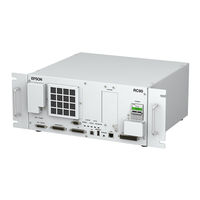
Epson RC90-B Manual (226 pages)
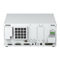
robot controller
Brand:
Epson
| Category:
Controller
| Size: 13.15 MB
Table of Contents
Table of Contents
11
Epson Rc+ 7.0
16
RC90 (EPSON RC+ 7.0) Rev
19
2 Conventions
20
Safety Precautions
20
Epson Rc+ 7.0
21
Epson Rc+ 7.0
22
Setup & Operation
23
Specifications
25
System Example
25
Standard Specifications
26
Outer Dimensions
28
Part Names and Functions
29
Part Names
29
Functions
29
Led
31
Safety Features
32
Installation
34
Unpacking
34
Environmental Requirements
34
Environment
34
Installation
35
Power Supply
36
Specifications
36
AC Power Cable
37
M/C Power Cable
38
Cable Connection
39
Typical Cable Connection
39
Connecting Manipulator to Controller
41
Noise Countermeasures
42
Operation Mode (TEACH/AUTO/TEST)
43
Overview
43
Switch Operation Mode
43
Program Mode (AUTO)
44
What Is Program Mode (AUTO)
44
Setup from EPSON RC+ 7.0
44
Auto Mode (AUTO)
45
What Is Auto Mode (AUTO)
45
Setup from EPSON RC+ 7.0
45
Setup from Control Device
46
Development PC Connection Port
47
About Development PC Connection Port
47
Precaution
48
Software Setup and Connection Check
48
Disconnection of Development PC and Controller
49
Memory Port
50
What Is Controller Status Storage Function
50
Before Using Controller Status Storage Function
50
Precautions
50
Adoptable USB Memory
50
Controller Status Storage Function
51
Controller Status Storage with Trigger Button
51
Load Data with EPSON RC+ 7.0
51
Transfer with E-Mail
53
Details of Data
53
LAN (Ethernet Communication) Port
54
About the LAN (Ethernet Communication) Port
54
IP Address
54
Changing Controller IP Address
55
Connection of Development PC and Controller with Ethernet
56
Disconnection of Development PC and Controller Withethernet
57
TP Port
58
What Is the TP Port
58
Teach Pendant Connection
58
Emergency
59
Safety Door Switch and Latch Release Switch
59
Safety Door Switch
60
Latch Release Switch
60
Checking Latch Release Switch Operation
61
Emergency Stop Switch Connection
62
Emergency Stop Switch
62
Checking Emergency Stop Switch Operation
62
Recovery from Emergency Stop
62
Pin Assignments
63
Circuit Diagrams
64
Example 1: External Emergency Stop Switch Typical Application48
64
Example 2: External Safety Relay Typical Application
65
Standard RS-232C Port
66
About the RS-232C Port
66
Confirmation with EPSON RC+ 7.0
66
RS-232C Software Communication Setup (RS-232C)
67
Communication Cable (RS-232C)
67
I/O Connector
68
Input Circuit
68
Typical Input Circuit Application 1
68
Typical Input Circuit Application 2
69
Output Circuit
70
Typical Output Circuit Application 1: Sink Type
71
Typical Output Circuit Application 2: Source Type
72
Pin Assignments
73
I/O Remote Settings
74
I/O Signal Description
75
Remote Input Signals
75
Remote Output Signals
79
Timing Specifications
82
Design Notes for Remote Input Signals
82
Timing Diagram for Operation Execution Sequence
82
Timing Diagram for Program Execution Sequence
82
Timing Diagram for Safety Door Input Sequence
83
Timing Diagram for Emergency Stop Sequence
83
Option Slots
84
What Are Option Slots
84
Expansion I/O Board
84
About Expansion I/O Board
84
Board Configuration (Expansion I/O)
84
Confirmation with EPSON RC+ 7.0
85
Input Circuit
85
Output Circuit
87
Pin Assignments
90
Fieldbus I/O Board
91
RS-232C Board
92
About the RS-232C Board
92
Board Setup
92
Confirmation with EPSON RC+ 7.0 (RS-232C)
93
RS-232C Software Communication Setup (RS-232C)
93
Communication Cable (RS-232C)
94
Maintenance
95
Safety Precautions on Maintenance
97
Safety Precautions
97
Lockout / Tagout
98
Installing the Lockout Attachment
98
Padlock Size and Weight
99
Safety Precautions
99
Regular Maintenance Inspection
100
Controller Structure
101
Location of Parts
101
Diagram of Cable Connections
101
Backup and Restore
102
What Is the Backup Controller Function
102
Backup Data Types
102
Backup
103
Restore
104
Firmware Update
106
Updating Firmware
106
Firmware Upgrade Procedure
106
Controller Recovery
109
Firmware Initialization Procedure
110
Alarm
112
Alarm Configuration
112
Robot Battery and Grease up
112
Controller Battery
113
How to View the Alarm Information
113
How to Edit the Alarm Information
114
Alarm Notifying Method
114
How to Cancel the Alarm
115
Alarm Cancellation Dialog
115
Remote Input
115
Maintenance Parts Replacement Procedures
116
Fan Filter
116
Fan
117
Battery
118
CF (Compact Flash)
119
Mdb
120
Dmb
122
DMB Sub Board
126
Option Board
127
Verifying Robot System Operation
129
Troubleshooting
130
Error Code Table
130
Cannot Connect the Development PC and the Controller Using the USB Cable
222
Confirmation Using Windows Device Manager
223
Device Manager
225
Maintenance Parts List
226
Advertisement
Epson RC90-B Safety And Installation (126 pages)
Robot System
Brand:
Epson
| Category:
Robotics
| Size: 6.5 MB
Table of Contents
Table of Contents
13
1 Safety
17
Conventions
17
Design and Installation Safety
18
Relevant Manuals
18
Designing a Safe Robot System
19
Operation Safety
23
Safety-Related Requirements
26
Part Names / Arm Motion
27
Operation Modes
31
Maintenance Safety
32
Emergency Stop
35
Free Running Distance in Emergency
35
How to Reset the Emergency Mode
40
Labels
40
Controller
41
Manipulator
42
Safety Features
47
Lockout / Tagout
50
Installing the Lockout Attachment
50
Padlock Size and Weight
51
Safety Precautions
51
Manipulator Specifications
52
Motion Range Setting by Mechanical Stops
59
End User Training
60
2 Installation
61
System Example
62
Outline from Unpacking to Operation of Robot System
63
Unpacking
64
Transportation
65
Transportation Precautions
65
Manipulator Transportation
66
Manipulator Installation
67
Installation Precautions
67
Environment
68
Noise Level
69
Base Table
70
Installation Procedure
71
Controller Installation
74
Installation Precautions
74
Environment
75
Installation
76
Connection to EMERGENCY Connector (Controller)
78
Safety Door Switch and Latch Release Switch
78
Safety Door Switch
79
Latch Release Switch
80
Checking Latch Release Switch Operation
81
Emergency Stop Switch
81
Checking Emergency Stop Switch Operation
82
Pin Assignments
83
Circuit Diagrams
84
Power Source
86
Power Supply
86
AC Power Cable
87
M/C Power Cable Connection
88
Connecting Manipulator and Controller
89
Power-On
90
Power-On Precautions
90
Power on Procedure
91
Saving Default Status
91
3 First Step
92
Installing EPSON RC+ 7.0 Software
92
Development PC and Controller Connection
95
About Development PC Connection Port
95
Precaution
96
Software Setup and Connection Check
96
Backup the Initial Condition of the Controller
97
Disconnection of Development PC and Controller
98
Moving the Robot to Initial Position
98
Writing Your First Program
102
4 Second Step
109
Connection with External Equipment
109
Remote Control
109
Ethernet
109
RS-232C (Option)
109
Analog I/O (Option)
109
Ethernet Connection of Development PC and Controller
110
Connection of Option Teaching Pendant
110
5 General Maintenance
111
Schedule for Maintenance Inspection
111
Manipulator
111
Controller
114
Overhaul (Parts Replacement)
115
Tightening Hexagon Socket Head Cap Bolts
117
Greasing
118
Handling and Disposal of Batteries
120
6 Manuals
122
Software
122
Software Options
122
Controller
123
Controller Options
123
Manipulator
123
7 Directives and Norms
124
Epson RC90-B Maintenance Manual (70 pages)
ROBOT CONTROLLER
Brand:
Epson
| Category:
Controller
| Size: 5.1 MB
Table of Contents
Table of Contents
11
Safety Precautions on Maintenance
15
Safety Precautions
15
Lockout / Tagout
16
Regular Maintenance Inspection
18
Inspection Point and Frequency
18
Timing of Replacement
18
Controller Structure
19
Location of Parts
19
For LS3-B, LS6-B
19
For LS10-B, LS20-B, LS6-B602S-V1
19
Diagram of Cable Connections
20
For LS3-B, LS6-B
20
For LS10-B, LS20-B, LS6-B602S-V1
20
Backup and Restore
21
What Is the Backup Controller Function
21
Backup Data Types
21
Backup
22
Restore
23
Firmware Update
26
Updating Firmware
26
Firmware Upgrade Procedure
26
Controller Recovery
29
Firmware Initialization Procedure
30
Adding Confirmation Steps by Strengthening Security of Ethernet Connection
32
Alarm
36
Before Controller Firmware Ver.7.1.8.X
37
Alarm Configuration
37
How to View the Alarm Information
38
How to Edit the Alarm Information
39
Alarm Notifying Method
39
How to Cancel the Alarm
40
Controller Firmware Ver.7.2.0.X or Later
41
Maintenance Information
41
How to View the Maintenance Information
42
How to Edit the Maintenance Information
44
Alarm Notifying Method
45
How to Cancel the Alarm
45
Option Parts Replacement Procedures
46
Option Board
46
EUROMAP67 Board
48
Maintenance Parts Replacement Procedures
50
Fan Filter
51
Fan
52
Battery
53
CF (Compact Flash)
55
Mdb
56
Dmb
58
DMB Sub Board
62
Dpb
63
Verifying Robot System Operation
65
Troubleshooting
66
Error Code Table
66
Cannot Connect the Development PC and the Controller Using the USB Cable
66
Confirmation Using Windows Device Manager
66
When Recognized under "Other Devices" in Windows Device
68
Manager
68
Maintenance Parts List
69
Advertisement
Advertisement
Related Products
Epson RC+
Epson RC90
Epson RC620 Series
Epson RC520
Epson RT3B-401SS
Epson RT6B-602SS
Epson RS Series
Epson RS3-351 Series
Epson RS4-551 Series
Epson RC620+
Epson Categories
Printer
Projector
All in One Printer
Scanner
Printer Accessories
More Epson Manuals
Login
Sign In
OR
Sign in with Facebook
Sign in with Google
Upload manual
Upload from disk
Upload from URL