Epson RC90 Series Maintenance Manual
Robot controller
Hide thumbs
Also See for RC90 Series:
- Manual (340 pages) ,
- User manual (218 pages) ,
- Safety and installation (124 pages)
Table of Contents
Advertisement
Quick Links
Advertisement
Table of Contents

Related Manuals for Epson RC90 Series


Summary of Contents for Epson RC90 Series
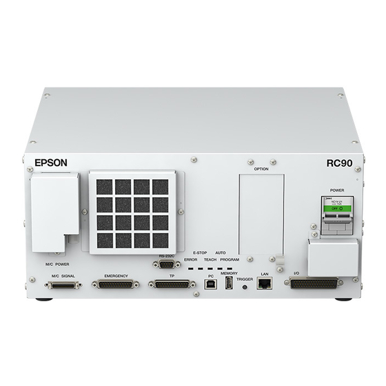
- Page 1 ROBOT CONTROLLER RC90 Series Maintenance Manual Rev.1 EM216C4692F RC90-B...
- Page 3 ROBOT CONTROLLER RC90 Series Maintenance Manual Rev.1 Copyright © 2021 SEIKO EPSON CORPORATION. All rights reserved. RC90 Series Maintenance Rev.1...
- Page 4 Please notify us if you should find any errors in this manual or if you have any comments regarding its contents. MANUFACTURER CONTACT INFORMATION Contact information is described in “SUPPLIERS” in the first pages of the following manual: Robot System Safety Manual Read this manual first RC90 Series Maintenance Rev.1...
- Page 5 For other countries, please contact your local government to investigate the possibility of recycling your product. The battery removal/replacement procedure is described in the following manuals: Maintenance Manual For California customers only The lithium batteries in this product contain Perchlorate Material - special handling may apply, See www.dtsc.ca.gov/hazardouswaste/perchlorate RC90 Series Maintenance Rev.1...
- Page 6 Operator Pendant OP500RC Jog Pad JP500 Teaching Pendant TP-3** Operator Panel OP1 For RC90-B, be sure to install the EPSON RC+7.0 to the development PC first, then connect the NOTE development PC and RC90-B with the USB cable. If RC90-B and the development PC are connected without installing the EPSON RC+7.0 to the development PC, [Add New Hardware Wizard] appears.
- Page 7 Ver.7.4.2.0 or later Before Ver.7.4.1 EPSON RC+ 7.0 Ver.7.4.2 or later OK: Compatible All functions of the EPSON RC+ 7.0 and the Controller are available. !!!: Compatible Connection is OK. We recommend using EPSON RC+7.0 Ver. 7.4.2 or later. NOTE ...
- Page 8 Ver.7.4.4.2 or later Before Ver.7.4.3 EPSON RC+ 7.0 Ver.7.4.4 or later OK: Compatible All functions of the EPSON RC+ 7.0 and the Controller are available. !!!: Compatible Connection is OK. We recommend using EPSON RC+7.0 Ver. 7.4.2 or later. RC90-B controller firmware LS6-B**** Ver.7.4.3.1 or later...
- Page 9 This manual contains a list of code numbers displayed on the controller and messages displayed in the software message area. The manual is primarily intended for people who design robot systems or do programming. RC90 series Maintenance Manual (PDF) xx series Maintenance Manual (PDF) (xx: Manipulator series name) This manual describes the details of maintenance etc.
- Page 10 EPSON RC+ 7.0 User’s Guide (PDF) This manual describes general information about program development software. EPSON RC+ 7.0 SPEL+ Language Reference (PDF) This manual describes the robot programming language “SPEL+”. Other Manual (PDF) Manuals for each option are available. viii...
-
Page 11: Table Of Contents
6.1.2 How to View the Alarm Information ..........26 6.1.3 How to Edit the Alarm Information ..........27 6.1.4 Alarm Notifying Method ............... 27 6.1.5 How to Cancel the Alarm ............28 6.2 Controller Firmware Ver.7.2.0.x or later ..........29 RC90 Series Maintenance Rev.1... - Page 12 10.2 Cannot Connect the Development PC and the Controller using the USB cable ....................54 10.2.1 Confirmation Using Windows Device Manager ......54 10.2.2 When recognized under “Other devices” in Windows Device Manager ..................56 11. Maintenance Parts List 12. Option Parts List RC90 Series Maintenance Rev.1...
- Page 13 RC90-B Maintenance This section contains maintenance procedures for RC90-B.
-
Page 15: Safety Precautions On Maintenance
■ Do not shock, shake, or drop any parts during maintenance. When the parts CAUTION related with data are shocked physically, they may be damaged and may also cause data loss during data loading/saving. RC90 Series Maintenance Rev.1... -
Page 16: Lockout / Tagout
Push the pin in the direction of arrows, and insert the pin POWER in the holes. switch (2) Turn the lockout (3) Install the lockout (4) Slide the pin to the attachment. attachment on the lock position. switch. Lock position RC90 Series Maintenance Rev.1... - Page 17 When using the padlock, do not use the controller where it is subject to vibration or ・ shock, otherwise failure or damage may result. Do not apply a force of more than 50N on the lockout attachment, otherwise the lockout ・ attachment will be damaged. RC90 Series Maintenance Rev.1...
-
Page 18: Regular Maintenance Inspection
(Rough) 2195107 Fan Filter 4 years or deteriorated 5 min. 8.1 Fan Filter 2157260 Error 515 occurred or noise 20 min. 8.2 Fan Battery Every 5 years or error 511 occurred 2113554 15 min. 8.3 Battery RC90 Series Maintenance Rev.1... -
Page 19: Controller Structure
3.1.1 For LS3-B, LS6-B MDB2 MDB1 Switching Power Supply Module Switching Power Supply Module Switching Power Supply Module DMB Sub Board Battery Option Slots 3.1.2 For LS10-B, LS20-B, LS6-B602S-V1 Regenerative MDB2 resistor MDB1 Option Slots DMB Sub Board Battery RC90 Series Maintenance Rev.1... -
Page 20: Diagram Of Cable Connections
3.2 Diagram of Cable Connections 3.2.1 For LS3-B, LS6-B (Connecters in the blue dotted line (RC90-B) work properly in any order.) 3.2.2 For LS10-B, LS20-B, LS6-B602S-V1 (Connecters in the blue dotted line (RC90-B) work properly in any order.) RC90 Series Maintenance Rev.1... -
Page 21: Backup And Restore
4. Backup and Restore 4.1 What is the Backup Controller Function? The controller configuration set by EPSON RC+ 7.0 can be stored with the “Backup Controller” function. The Controller settings can be restored easily using the data previously stored with “Backup Controller”... -
Page 22: Backup
Maintenance 4. Backup and Restore 4.3 Backup Backup the Controller status from the EPSON RC+ 7.0. (1) Select EPSON RC+ 7.0 menu-[Tools]-[Controller] to display the [Controller Tools] dialog. (2) Click the <Backup Controller…> button to display the [Browse For Folder] dialog. -
Page 23: Restore
■ Do not edit the backup files. Otherwise, operation of the robot system after data CAUTION restoration to the Controller is not assured. (1) Select the EPSON RC+ 7.0 menu-[Tools]-[Controller] to display the [Controller Tools] dialog. (2) Click the <Restore Controller…> button to display the [Browse For Folder] dialog. - Page 24 This is not selected by the default setting. When a project is restored, the values of Global Preserve variables are loaded. For details about Global Preserve variable backup, refer to EPSON RC+ 7.0 User’s Guide 5.10.10 Display Variables Command (Run Menu).
- Page 25 When different system information is restored, the following warning message appears. Click the <No> button (do not restore data) except for special situations such as controller replacement. NOTE When restoring the backup including unsupported robot information to the target controller, an error occurs. RC90 Series Maintenance Rev.1...
-
Page 26: Firmware Update
Controller firmware is supplied by CD-ROM as needed. Please contact the supplier of your region for information. You must use a PC running EPSON RC+ 7.0 connected to a Controller with USB to update the Controller firmware. Firmware cannot be updated with an Ethernet connection. - Page 27 (7) Check the current firmware version and the new firmware version and click the <Install> button. (8) The firmware upgrade starts. It takes several minutes to complete. NOTE Do not disconnect the USB cable during transfer or turn OFF the Controller or the development PC. RC90 Series Maintenance Rev.1...
- Page 28 The firmware upgrade is complete. When you install the firmware (Ver.7.4.0.2 or later) on the controller which the firmware NOTE (before Ver.7.4.0.2) has been installed, the following message is displayed. When the message is displayed, re-install the firmware. RC90 Series Maintenance Rev.1...
-
Page 29: Controller Recovery
30 seconds. This will cause the Controller to start in Recovery mode. (3) Make sure that the LED of ERROR, TEACH, and PROGRAM are lighting. (4) Follow the procedure in 5.4 Firmware Initialization Procedure from step (3) to initialize the firmware. RC90 Series Maintenance Rev.1... -
Page 30: Firmware Initialization Procedure
(1) Connect the development PC to the Controller with a USB cable (the firmware cannot be changed with an Ethernet connection). (2) Turn ON the Controller. Do not start the development software EPSON RC+ 7.0 until firmware initialization is complete. - Page 31 (10) The following dialog appears after the Controller reboot. Click the <Finish> button. The firmware upgrade is completed. Start EPSON RC+ 7.0 and restore the Controller settings. For details of restoring the operating system, refer to 4. Backup and Restore.
-
Page 32: Adding Confirmation Steps By Strengthening Security Of Ethernet Connection
Controller IP address is set to global IP address Firmware version is 7.4.8.x or later EPSON RC+7.0 is Ver.7.4.7 or before When the Controller firmware is updated under the following conditions, additional steps to confirm whether to continue the firmware update may be execute depending on the configuration settings of the Controller. - Page 33 When the <OK> button is clicked, Step3 window is displayed. Go to the step (6). When the <Cancel> button is clicked, Step3 window is displayed. The [Disable connection password] checkbox and the <Install> button will be grayed out and cannot be selected. RC90 Series Maintenance Rev.1...
- Page 34 When the <OK> button is clicked, Step 4 window is displayed. Go to the step (7). When the <Cancel> button is clicked, the window is closed. (7) Firmware installation starts. When the firmware is installed, click the <Next> button. Reboot the Controller. RC90 Series Maintenance Rev.1...
- Page 35 Maintenance 5. Firmware Update (8) When the Controller is rebooted, the following window is displayed. Confirm that the firmware is installed. Click the <Finish> button. RC90 Series Maintenance Rev.1...
-
Page 36: Alarm
- Robot battery replacement - Grease up Ver.7.2.0.x or later - Replacement of the timing belt - Replacement of the motor - Replacement of the reduction gear unit - Replacement of the ball screw spline unit RC90 Series Maintenance Rev.1... -
Page 37: Before Controller Firmware Ver.7.1.8.X
Ball screw spline unit on the Joint # 3 When the robot is deleted from the configuration, the alarm will also be automatically deleted. For details on the robot configuration, refer to the EPSON RC+ 7.0 User’s Guide 10.1 Setting the Robot Model. ... -
Page 38: How To View The Alarm Information
Maintenance 6. Alarm 6.1.1.2 Controller Battery The controller battery is automatically configured at the first connection with the EPSON RC+7.0 after upgrading to the firmware version 7.1.0.x and later. If you are using the controller before the version upgrade, there may be a difference in the NOTE ... -
Page 39: How To Edit The Alarm Information
6.1.4 Alarm Notifying Method The alarm notifying method needs to be configured by the output bit of the Remote I/O. The Remote I/O can be configured in the EPSON RC+ 7.0- [Setup] - [System Configuration] - [Controller] - [Remote Control]. -
Page 40: How To Cancel The Alarm
By referring to 6.1.3 How to Edit the Alarm, change the alarm information in the same steps. 6.1.5.2 Remote Input The alarm can be canceled by the input bit of the Remote I/O. For details, refer to the EPSON RC+ 7.0 User’s Guide 12.1 Remote I/O. RC90 Series Maintenance Rev.1... -
Page 41: Controller Firmware Ver.7.2.0.X Or Later
Initial installation : Maintenance is enabled. Upgrade : Maintenance inherits the previous data. (Disables as default) For details for enabling or disabling the maintenance, refer to the EPSON RC+ 7.0 User’s Guide 5.12.2 [System Configuration] Command (Setup Menu) - [Setup]-[System Configuration]-[Controller]-[Preferences] Page NOTE ... -
Page 42: How To View The Maintenance Information
6.2.1.2 Controller Maintenance Information If the maintenance is enabled, the controller battery is automatically configured at the first connection with the EPSON RC+7.0 after upgrading to the firmware version 7.2.0.x and later. If you are using the controller before the version upgrade, there may be a difference in the NOTE ... - Page 43 Remaining months is calculated based on the past operation conditions. Enable to set the period for calculation by “HealthCalcPeriod” command. (Default: seven days of the controller ON time) Remaining months may not be calculated properly until the period for the calculation passed. RC90 Series Maintenance Rev.1...
-
Page 44: How To Edit The Maintenance Information
Maintenance 6. Alarm 6.2.3 How to Edit the Maintenance Information The configured maintenance information can be edited in the EPSON RC+ 7.0 Ver.7.2.x or later. (1) Select the EPSON RC+ 7.0 menu-[Tools]-[Maintenance] to display the [Controller Tools] dialog box. (2) To edit the maintenance information, display the [Maintenance] dialog box. -
Page 45: Alarm Notifying Method
Status Code / Error Code List Manual The alarm notifying method can be configured by the output bit of the Remote I/O. The Remote I/O can be configured in the EPSON RC+ 7.0- [Setup] - [System Configuration] - [Controller] - [Remote Control]. -
Page 46: Option Parts Replacement Procedures
(6) Install the Option Board as shown in the picture. (7) Mount the attachment L-shaped plate with a screw from the front side. At this point, one screw for the Option Slot Panel is left unused. RC90 Series Maintenance Rev.1... - Page 47 For LS3-B, LS6-B: Mounting screw ×10 For LS10-B, LS20-B, LS6-B602S-V1: Mounting screw ×6 (11) Connect the power plug. Turn ON the Controller and make sure that the Controller starts properly without any vibration or abnormal noise. RC90 Series Maintenance Rev.1...
-
Page 48: Euromap67 Board
Maintenance 7. Option Parts Replacement Procedures 7.2 EUROMAP67 Board For the detail of the board, refer to the RC90 Series Manual. (1) Turn OFF the Controller. (2) Disconnect the power plug. (3) Remove the Top Panel. (Mounting screw ×10) (4) Insert the EUROMAP67 board into slots. - Page 49 (10) Mount the Top Panel. (Mounting screw ×10. (11) Connect “Cable2 CN4” to the IMM. (12) Connect the power plug. Turn ON the Controller and make sure that the Controller starts properly without any vibration or abnormal noise. RC90 Series Maintenance Rev.1...
-
Page 50: Maintenance Parts Replacement Procedures
Refer to the following pictures if you need to remove the top panel for maintenance. For LS3-B, LS6-B: Mounting screws×10 Back Back: Refer to the picture on the right For LS10-B, LS20-B, LS6-B602S-V1: Mounting screws×6 Top only RC90 Series Maintenance Rev.1... -
Page 51: Fan Filter
(1) Set the fan filter to the fan filter cover. Installation (2) Mount the fan filter cover with two screws. (3) Connect the power plug. Turn ON the Controller and make sure that the Controller starts properly without any vibration or abnormal noise. RC90 Series Maintenance Rev.1... -
Page 52: Fan
For LS3-B, LS6-B: Mounting screws ×10 For LS10-B, LS20-B, LS6-B602S-V1: Mounting screws ×6 (4) Connect the power plug. Turn ON the Controller and make sure that the Controller starts properly without any vibration or abnormal noise. RC90 Series Maintenance Rev.1... -
Page 53: Battery
・Forced Discharge CAUTION ■ Be sure to use the battery supplied as maintenance part from EPSON. (Refer to 11. Maintenance Parts List.) ■ When disposing of the battery, consult with the professional disposal services or comply with the local regulation. - Page 54 For LS3-B, LS6-B: Mounting screws ×10 For LS10-B, LS20-B, LS6-B602S-V1: Mounting screws ×6 (4) Connect the power plug. Turn ON the Controller and make sure that the Controller starts properly without any vibration or abnormal noise. RC90 Series Maintenance Rev.1...
-
Page 55: Cf (Compact Flash)
For LS3-B, LS6-B: Mounting screws ×10 For LS10-B, LS20-B, LS6-B602S-V1: Mounting screws ×6 (4) Connect the power plug. Turn ON the Controller and make sure that the Controller starts properly without any vibration or abnormal noise. RC90 Series Maintenance Rev.1... -
Page 56: Mdb
(6) Pull out the MDB clamp for the upright mounting. (7) Remove the screws on the chassis side surface. (×2) (8) Remove the MDB clamp. (Mounting screw ×2) (9) Pull out the MDB in the direction shown in the picture. RC90 Series Maintenance Rev.1... - Page 57 For LS3-B, LS6-B: Mounting screws ×10 For LS10-B, LS20-B, LS6-B602S-V1: Mounting screws ×6 (8) Connect the power plug. Turn ON the Controller and make sure that the Controller starts properly without any vibration or abnormal noise. RC90 Series Maintenance Rev.1...
-
Page 58: Dmb
(8) Remove the fan. Refer to : 8.2 Fan. (9) Remove the cover for the M/C Power Connector. (10) Remove the screw of the clamp for the M/C Power Cable (×1) and screws of the M/C Power Connector (×2). RC90 Series Maintenance Rev.1... - Page 59 (11) Remove the FG line of the M/C Power Cable. (12) Disconnect the M/C Power Cable from the chassis front side. (13) Remove the DMB from the chassis. At this point, be careful not to touch the chassis and other parts. RC90 Series Maintenance Rev.1...
- Page 60 (5) Remove the cover for the M/C Power Connector. (6) Mount the fan. Refer to : 8.2 Fan. (7) Tighten the DMB mounting screw (×14). (8) Connect the connectors (×4). (9) Mount the MDB. Refer to : 8.5 MDB. RC90 Series Maintenance Rev.1...
- Page 61 For LS3-B, LS6-B: Mounting screws ×10 For LS10-B, LS20-B, LS6-B602S-V1: Mounting screws ×6 (12) Connect the power plug. Turn ON the Controller and make sure that the Controller starts properly without any vibration or abnormal noise. RC90 Series Maintenance Rev.1...
-
Page 62: Dmb Sub Board
For LS3-B, LS6-B: Mounting screws ×10 For LS10-B, LS20-B, LS6-B602S-V1: Mounting screws ×6 (6) Connect the power plug. Turn ON the Controller and make sure that the Controller starts properly without any vibration or abnormal noise. RC90 Series Maintenance Rev.1... -
Page 63: Dpb
Remove the rear plate from the Controller. Mounting screws × 7 (7) Unscrew the DPB mounting screws. For LS3-B, LS6-B: For LS10-B, LS20-B, LS6-B602S-V1: : Mounting screws × 9 : Mounting screws × 12 (8) Remove the DPB from the Controller. RC90 Series Maintenance Rev.1... - Page 64 For LS3-B, LS6-B: Mounting screws ×10 For LS10-B, LS20-B, LS6-B602S-V1: Mounting screws ×6 (7) Connect the power plug. Turn ON the Controller and make sure that the Controller starts properly without any vibration or abnormal noise. RC90 Series Maintenance Rev.1...
-
Page 65: Verifying Robot System Operation
(2) Turn ON the Controller. The Controller will boot up. During this process, watch and monitor the LED status. For details of the display, refer to RC90 Series Manual 2.3 LED. For error number, refer to Status Code / Error Code List Manual. -
Page 66: Troubleshooting
Click the <Cancel> button to close the [Add New Hardware] wizard.. - If the following error message appears when connecting the development PC and Controller with the USB cable and connecting the Controller to EPSON RC+ 7.0, Windows may not recognize the Controller properly. - Page 67 !! Error: 1805, Connection failure, check the controller startup and connection of the communication cable.” If “EPSON Robot Controller” is not located under “Universal Serial Bus controllers” but located under “Other devices” in step (4), refer to 10.2.2 When recognized under “Other devices”...
-
Page 68: When Recognized Under "Other Devices" In Windows Device
(3) The [Uninstall Device] dialog appears. Click the <Uninstall> button. Remove the USB cable and connect the USB cable again. The massage, “Install EPSON Robot Controller”, will be displayed at the bottom right of the window screen. Controller is installed automatically. -
Page 69: Maintenance Parts List
For LS20-B (Joint #1, #2) − For LS10-B , LS6-B602S-V1 (Joint #1, #2) 30A/15A 2191087 Motor − For LS20-B , LS6-B602S-V1 Driver (Joint #3, #4) 15A/15A-2 2194709 For LS10-B (Joint #3, #4) − 10A/10A 2195536 For LS3-B, LS6-B − RC90 Series Maintenance Rev.1... - Page 70 − Emergency Stop cable For EUROMAP67 Board EUROMAP67 Cable2 2194668 − IMM Connection cable EUROMAP67 Emergency For EUROMAP67 Board Connector 2165789 − Soldering plug Plug EUROMAP67 Emergency For EUROMAP67 Board 2194882 − Connector Shell kit Shell RC90 Series Maintenance Rev.1...