Sign In
Upload
Manuals
Brands
ABB Manuals
Control Unit
ACH480
ABB ACH480 Manuals
Manuals and User Guides for ABB ACH480. We have
4
ABB ACH480 manuals available for free PDF download: Hardware Manual, Manual, Quick Installation And Start-Up Manual
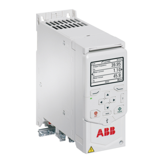
ABB ACH480 Hardware Manual (214 pages)
Brand:
ABB
| Category:
DC Drives
| Size: 8.15 MB
Table of Contents
Table of Contents
5
1 Safety Instructions
15
Contents of this Chapter
15
Use of Warnings and Notes
15
General Safety in Installation, Start-Up and Maintenance
16
Electrical Safety in Installation, Start-Up and Maintenance
17
Electrical Safety Precautions
17
Additional Instructions and Notes
18
Printed Circuit Boards
18
Grounding
18
General Safety in Operation
20
Additional Instructions for Permanent Magnet Motor Drives
20
Safety in Installation, Start-Up, Maintenance
20
Safety in Operation
21
2 Introduction to the Manual
23
Contents of this Chapter
23
Applicability
23
Target Audience
23
Categorization by Frame Size
23
Quick Installation and Commissioning Flowchart
24
Terms and Abbreviations
25
Related Manuals
26
3 Operation Principle and Hardware Description
29
Contents of this Chapter
29
Operation Principle
29
Simplified Main Circuit Diagram
30
Product Variants
30
IEC and UL (NEC) Product Types
30
Layout
31
Control Connections
32
Standard Unit
32
Base Unit
33
Option Modules
33
Control Panel Options
34
UL Type 1 Kits
34
Type Designation Label
35
Type Designation Key
36
Basic Code
36
Option (Plus) Codes
36
4 Mechanical Installation
39
Contents of this Chapter
39
Installation Alternatives
39
Examining the Installation Site
40
Required Tools
40
Unpacking the Delivery
41
Installing the Drive
41
To Install the Drive with Screws
41
To Install the Drive to a DIN Installation Rail
42
5 Guidelines for Planning the Electrical Installation
45
Contents of this Chapter
45
Limitation of Liability
45
Selecting the Main Supply Disconnecting Device
45
European Union
45
North America
46
Other Regions
46
Selecting the Main Contactor
46
Checking the Compatibility of the Motor and Drive
46
Selecting the Power Cables
46
General Guidelines
46
Typical Power Cable Sizes
47
Power Cable Types
48
Preferred Power Cable Types
48
Alternate Power Cable Types
49
Not Allowed Power Cable Types
50
Additional Guidelines, North America
50
Metal Conduit
51
Power Cable Shield
51
Selecting the Control Cables
52
Shielding
52
Signals in Separate Cables
52
Signals that Can be Run in the same Cable
52
Relay Cable
52
Control Panel to Drive Cable
52
PC Tool Cable
52
Routing the Cables
53
General Guidelines - IEC
53
General Guidelines - North America
53
Continuous Motor Cable Shield/Conduit or Enclosure for Equipment on the Motor Cable
54
Separate Control Cable Ducts
55
Implementing Short-Circuit and Thermal Overload Protection
55
Protecting the Drive and Input Power Cable in Short-Circuits
55
Protecting the Motor and Motor Cable in Short-Circuits
55
Protecting the Drive, and the Input Power and Motor Cables against Thermal Overload
55
Protecting the Motor against Thermal Overload
56
Protecting the Motor against Overload Without Thermal Model or Temperature Sensors
56
Implementing a Motor Temperature Sensor Connection
56
Protecting the Drive against Ground Faults
57
Residual Current Device Compatibility
57
Implementing the Emergency Stop Function
57
Implementing the Safe Torque off Function
58
Using a Safety Switch between the Drive and the Motor
58
Implementing the Control of a Contactor between Drive and Motor
58
Protecting the Contacts of Relay Outputs
58
6 Electrical Installation - IEC
61
Contents of this Chapter
61
Warnings
61
Required Tools
61
Measuring the Insulation
62
Measuring the Insulation of the Drive
62
Measuring the Insulation of the Input Power Cable
62
Measuring the Insulation of the Motor and Motor Cable
62
Measuring the Insulation of the Brake Resistor Circuit
63
Earthing System Compatibility Check - IEC
63
EMC Filter
64
Ground-To-Phase Varistor
64
When to Disconnect EMC Filter or Ground-To-Phase Varistor
64
Disconnecting the EMC Filter or Ground-To-Phase Varistor
66
EMC/VAR Screw Location
66
Guidelines for Installing the Drive to a TT System
67
Identifying the Earthing System of the Electrical Power Network
67
Connecting the Power Cables - IEC (Shielded Cables)
69
Connection Diagram
69
Connection Procedure
70
Connecting the Control Cables
72
Default I/O Connection Diagrams (HVAC Default)
72
Default Fieldbus Connection Diagram
74
Control Cable Connection Procedure
75
Additional Information on the Control Connections
75
Connecting EIA-485 Fieldbus Cable to the Drive
75
PNP Configuration for Digital Inputs
76
NPN Configuration for Digital Inputs
77
Connection for Obtaining 0
77
Connection Examples of Two-Wire and Three-Wire Sensors
78
AI and AO (or AI, DI and +10 V) as PTC Motor Temperature Sensor Interface
78
AI1 and AI2 as Pt100, Pt1000, Ni1000, KTY83 and KTY84 Sensor Inputs
80
Safe Torque off
81
Auxiliary Voltage Connection
81
Connecting a PC
82
Installing Options
82
Installing a Front Option
83
Installing a Side Option
84
7 Electrical Installation - North America
87
Contents of this Chapter
87
Warnings
87
Required Tools
87
Measuring the Insulation
88
Measuring the Insulation of the Drive
88
Measuring the Insulation of the Input Power Cable
88
Measuring the Insulation of the Motor and Motor Cable
88
Measuring the Insulation of the Brake Resistor Circuit
89
Earthing System Compatibility Check - North America
89
EMC Filter
90
Ground-To-Phase Varistor
90
When to Disconnect Ground-To-Phase Varistor, or Connect EMC Filter
90
Disconnecting the Ground-To-Phase Varistor, or Connecting the EMC Filter
92
EMC/VAR Screw Location
92
Guidelines for Installing the Drive to a TT System
93
Identifying the Earthing System of the Electrical Power Network
93
Connecting the Power Cables - North America (Wiring in Conduits)
94
Connection Diagram
95
Connection Procedure
95
Connecting the Control Cables
96
Default I/O Connection Diagrams (HVAC Default)
96
Default Fieldbus Connection Diagram
98
Control Cable Connection Procedure
99
Additional Information on the Control Connections
100
Connecting EIA-485 Fieldbus Cable to the Drive
100
PNP Configuration for Digital Inputs
101
NPN Configuration for Digital Inputs
101
Connection for Obtaining 0
102
Connection Examples of Two-Wire and Three-Wire Sensors
102
AI and AO (or AI, DI and +10 V) as PTC Motor Temperature Sensor Interface
103
AI1 and AI2 as Pt100, Pt1000, Ni1000, KTY83 and KTY84 Sensor Inputs
104
Safe Torque off
105
Auxiliary Voltage Connection
105
Connecting a PC
106
Installing Options
106
Installing a Front Option
107
Installing a Side Option
108
8 Installation Checklist of the Drive
111
Contents of this Chapter
111
Checklist
111
9 Maintenance
115
Contents of this Chapter
115
Maintenance Intervals
115
Cleaning the Heatsink
116
Replacing the Cooling Fans
117
To Replace the Cooling Fan for Frame Sizes R1, R2 and R3
117
To Replace the Cooling Fan for Frame R4
119
Capacitors
121
Reforming the Capacitors
121
10 Technical Data
123
Contents of this Chapter
123
Electrical Ratings
123
IEC Ratings
123
UL (NEC) Ratings
124
Definitions
125
Sizing
125
Output Derating
125
Surrounding Air Temperature Derating
128
Altitude Derating
128
Switching Frequency Derating
128
Fuses
130
IEC Fuses
130
Gg Fuses (IEC)
130
Gr Fuses (IEC)
131
UL (NEC) Fuses
131
UL (NEC) Fuse Alternatives
132
Alternate Short-Circuit Protection
134
Miniature Circuit Breakers (IEC)
134
Manual Self-Protected Combination Motor Controller - Type E USA (UL (NEC))
135
Dimensions and Weights
137
Free Space Requirements
138
Losses, Cooling Data and Noise
138
Typical Power Cable Sizes
139
Terminal Data for the Power Cables
140
Terminal Data for the Control Cables
141
External EMC Filters
142
Electrical Power Network Specification
143
Motor Connection Data
143
Motor Cable Length
144
Operational Functionality and Motor Cable Length
144
EMC Compatibility and Motor Cable Length
144
Brake Resistor Connection Data
145
Control Connection Data
145
Efficiency
146
Protection Classes
146
Ambient Conditions
146
Materials
147
Disposal
147
Applicable Standards
148
Markings
148
EMC Compliance (IEC/EN 61800-3:2004 + A1:2012)
149
Definitions
149
Category C1
150
Category C2
150
Category C3
151
Category C4
151
UL Checklist
152
Disclaimers
153
Generic Disclaimer
153
Cybersecurity Disclaimer
154
11 Dimension Drawings
155
Contents of this Chapter
155
Frame R1
156
Frame R1 (Front & Side) - IP20 / UL Open Type
156
Frame R1 (Bottom & Rear) - IP20 / UL Open Type
157
Frame R1 (Front & Side) - UL Type 1 Kit Installed
158
Frame R1 (Bottom & Rear) - UL Type 1 Kit Installed
159
Frame R2
160
Frame R2 (Front & Side) - IP20 / UL Open Type
160
Frame R2 (Bottom & Rear) - IP20 / UL Open Type
161
Frame R2 (Front & Side) - UL Type 1 Kit Installed
162
Frame R2 (Bottom & Rear) - UL Type 1 Kit Installed
163
Frame R3
164
Frame R3 (Front & Side) - IP20 / UL Open Type
164
Frame R3 (Bottom & Rear) - IP20 / UL Open Type
165
Frame R3 (Front & Side) - UL Type 1 Kit Installed
166
Frame R3 (Bottom & Rear) - UL Type 1 Kit Installed
167
Frame R4
168
Frame R4 (Front & Side) - IP20 / UL Open Type
168
Frame R4 (Bottom & Rear) - IP20 / UL Open Type
169
Frame R4 (Front & Side) - UL Type 1 Kit Installed
170
Frame R4 (Bottom & Rear) - UL Type 1 Kit Installed
171
12 Resistor Braking
173
Contents of this Chapter
173
Safety
173
Operation Principle
173
Selecting the Brake Resistor
173
Reference Brake Resistors
175
Definitions
176
Selecting and Routing the Brake Resistor Cables
176
Minimizing Electromagnetic Interference
176
Maximum Cable Length
176
Placing the Brake Resistors
176
Protecting the System in Brake Circuit Fault Situations
177
Protecting the System in Cable and Brake Resistor Short-Circuit Situations
177
Protecting the System against Thermal Overload
177
Mechanical and Electrical Installation of Brake Resistor
178
Mechanical Installation
178
Electrical Installation
179
Measuring the Insulation
179
Connecting Power Cables
179
Connection the Control Cables
179
Start-Up
179
13 The Safe Torque off Function
181
Contents of this Chapter
181
Description
181
Compliance with the European Machinery Directive
182
Wiring
183
Connection Principle
183
Single ACH480 Drive, Internal Power Supply
183
Single ACH480 Drive, External Power Supply
184
Wiring Examples
185
Single ACH480 Drive, Internal Power Supply
185
Single ACH480 Drive, External Power Supply
185
Multiple ACH480 Drives, Internal Power Supply
186
Multiple ACH480 Drives, External Power Supply
187
Activation Switch
187
Cable Types and Lengths
188
Grounding of Protective Shields
188
Operation Principle
189
Start-Up Including Acceptance Test
190
Competence
190
Acceptance Test Reports
190
Acceptance Test Procedure
190
Use
192
Maintenance
193
Competence
193
Fault Tracing
194
Safety Data
195
Abbreviations
196
TÜV Certificate
197
Declaration of Conformity
198
14 BAPO-01 Auxiliary Power Extension Module
199
Contents of this Chapter
199
Safety Instructions
199
Hardware Description
199
Layout
200
Mechanical Installation
200
Electrical Installation
200
Start-Up
201
Technical Data
201
15 BIO-01 I/O Extension Module
203
Contents of this Chapter
203
Safety Instructions
203
Hardware Description
203
Product Overview
203
Layout
204
Mechanical Installation
204
Electrical Installation
204
Start-Up
205
Technical Data
205
16 BREL-01 Relay Output Extension Module
207
Contents of this Chapter
207
Safety Instructions
207
Hardware Description
207
Product Overview
207
Layout
208
Mechanical Installation
208
Electrical Installation
208
Start-Up
209
Configuration Parameters
209
Technical Data
211
Further Information
213
Advertisement
ABB ACH480 Hardware Manual (152 pages)
Brand:
ABB
| Category:
DC Drives
| Size: 7.34 MB
Table of Contents
Table of Contents
5
Safety Instructions
11
Contents of this Chapter
11
Use of Warnings and Notes in this Manual
11
General Safety in Installation, Start-Up and Maintenance
12
Electrical Safety in Installation, Start-Up and Maintenance
13
Precautions before Electrical Work
13
Additional Instructions and Notes
14
Grounding
15
Additional Instructions for Permanent Magnet Motor Drives
16
Safety in Installation, Start-Up and Maintenance
16
General Safety in Operation
17
Introduction to the Manual
19
Contents of this Chapter
19
Applicability
19
Target Audience
19
Purpose of the Manual
19
Contents of this Manual
20
Related Documents
20
Categorization by Frame (Size)
20
Quick Installation and Commissioning Flowchart
21
Hardware Description
25
Contents of this Chapter
25
General Description
25
Product Variants
25
Hardware Overview
26
Control Connections
27
Standard Unit
27
Base Unit
28
Mounted Options
29
Control Panel
29
PC Connection
29
Drive Labels
30
Model Information Label
30
Software Information Label
30
Type Designation Label
31
Type Designation Key
32
Operation Principle
34
Mechanical Installation
35
Contents of this Chapter
35
Examining the Installation Site
36
Required Tools
36
Unpacking the Delivery
37
Installing the Drive
38
To Install the Drive with Screws
38
To Install the Drive to a DIN Installation Rail
39
Planning the Electrical Installation
41
Contents of this Chapter
41
Selecting the Supply Disconnecting Device
41
European Union
41
Other Regions
42
Checking the Compatibility of the Motor and Drive
42
Selecting the Power Cables
42
Typical Power Cable Sizes
43
Recommended Power Cable Types
45
Power Cable Types for Limited Use
45
Not Allowed Power Cable Types
45
Motor Cable Shield
46
Additional US Requirements
46
Selecting the Control Cables
48
Shielding
48
Signals in Separate Cables
48
Signals that Can be Run in the same Cable
48
Relay Cable
48
Control Panel to PC Connection
48
Control Panel to Drive Connection
48
Modbus RTU Cable
48
Routing the Cables
49
Separate Control Cable Ducts
50
Continuous Motor Cable Shield or Conduit
50
Implementing Short-Circuit Protection
50
Protecting the Drive and Input Power Cable in Short-Circuits
50
Protecting the Motor and Motor Cable in Short-Circuits
50
Implementing Thermal Overload Protection
51
Protecting the Drive, and the Input Power and Motor Cables against Thermal Overload
51
Protecting the Motor against Thermal Overload
51
Protecting the Drive against Ground Faults
51
Residual Current Device Compatibility
51
Implementing the Emergency Stop Function
52
Implementing the Safe Torque off Function
52
Using a Safety Switch between the Drive and Motor
52
Using a Contactor between the Drive and Motor
52
Protecting the Contacts of Relay Outputs
53
Electrical Installation
55
Contents of this Chapter
55
Warnings
55
Required Tools
55
Measuring Insulation
56
Drive
56
Input Power Cable
56
Motor and Motor Cable
56
Brake Resistor Assembly
56
Compatibility with IT (Ungrounded) and Corner-Grounded TN Systems
57
EMC Filter
57
EMC Filter Disconnection
57
Ground-To-Phase Varistor
58
Connecting the Power Cables
59
Connection Diagram
59
Connection Procedure
60
Connecting the Control Cables
62
I/O Connections (HVAC Default)
63
Connecting EIA-485 Embedded Fieldbus Terminal to the Drive
65
Control Cable Connection Procedure
67
Auxiliary Voltage Connection
68
Option Modules
69
To Install a Front Option
70
To Remove a Front Option
71
To Install a Side Option
71
To Remove a Side Option
71
Installation Checklist
73
Contents of this Chapter
73
Warnings
73
Checklist
73
Maintenance
75
Contents of this Chapter
75
Maintenance Intervals
76
Cleaning the Heat Sink
77
Replacing the Cooling Fans
78
To Replace the Cooling Fan for Frame Sizes R1, R2 and R3
78
To Replace the Cooling Fan for Frame R4
80
Servicing the Capacitors
81
Capacitor Reforming
81
Technical Data
83
Contents of this Chapter
83
Ratings
84
IEC Ratings
84
NEMA Ratings
84
Definitions
85
Sizing
85
Derating
85
Surrounding Air Temperature Derating, IP20
86
Switching Frequency Derating
86
Altitude Derating
87
Fuses (IEC)
88
Gg Fuses
88
Gr Fuses
89
UL Fuses
89
Alternate Short-Circuit Protection
90
Miniature Circuit Breakers (IEC Environment)
90
Self-Protected Combination Manual Controller - Type EUSA (UL) Environment
91
Dimensions and Weights
92
Free Space Requirements
93
Losses, Cooling Data and Noise
93
Terminal Data for the Power Cables
94
Terminal Data for the Control Cables
94
External EMC Filters
95
Electric Power Network Specification
96
Motor Cable Length
97
Motor Connection Data
97
Control Connection Data
99
Brake Resistor Connection
100
Efficiency
100
Degrees of Protection
100
Ambient Conditions
101
Materials
102
Applicable Standards
103
CE Marking
104
Compliance with the European Low Voltage Directive
104
Compliance with the European EMC Directive
104
Compliance with the European Rohs Directive
104
Compliance with the European WEEE Directive
104
Compliance with the European Machinery Directive
105
Compliance with en 61800-3:2004 + A1:2012
106
Definitions
106
Category C1
106
Category C2
106
Category C3
107
UL Marking
108
UL Checklist
108
CSA Marking
109
RCM Marking
109
EAC Marking
109
WEEE Marking
109
China Rohs Marking
109
TÜV Marking
110
Disclaimers
110
Generic Disclaimer
110
Cyber Security Disclaimer
110
Dimension Drawings
111
Frame R1 (400 V) (Front & Side)
112
Frame R1 (400 V) (Bottom & Rear)
113
Frame R2 (400 V) (Front & Side)
114
Frame R2 (400 V) (Bottom & Rear)
115
Frame R3 (Front & Side)
116
Frame R3 (Bottom & Rear)
117
Frame R4 (Front & Side)
118
Frame R4 (Bottom & Rear)
119
Resistor Braking
121
Contents of this Chapter
121
Operation Principle and Hardware Description
121
Selecting the Brake Resistor
121
Reference Brake Resistors
123
Selecting and Routing the Brake Resistor Cables
124
Minimizing Electromagnetic Interference
124
Maximum Cable Length
124
EMC Compliance of the Complete Installation
124
Brake Resistor Installation
124
Protecting the System in Brake Circuit Fault Situations
125
Protecting the System in Cable and Brake Resistor Short-Circuit Situations
125
Protecting the System against Thermal Overload
125
Mechanical Installation
125
Electrical Installation
126
Measuring the Insulation of the Assembly
126
Connection Diagram
126
Connection Procedure
126
Start-Up
127
Safe Torque off Function
129
Contents of this Chapter
129
Description
129
Compliance with the European Machinery Directive
130
Connection Principle
131
Connection with Internal +24 V DC Power Supply
131
Connection with External +24 V DC Power Supply
131
Wiring Examples
132
Activation Switch
132
Cable Types and Lengths
133
Grounding of Protective Shields
133
Operation Principle
133
Start-Up Including Acceptance Test
134
Competence
134
Acceptance Test Reports
134
Acceptance Test Procedure
135
Use
136
Maintenance
138
Competence
138
Fault Tracing
139
Safety Data
140
Abbreviations
141
Declaration of Conformity
142
TÜV Certificate
142
BAPO-01 Power Extension Module
143
Contents of this Chapter
143
Safety Instructions
143
Hardware Description
144
Product Overview
144
Layout
144
Mechanical Installation
145
Electrical Installation
145
Start-Up
145
Technical Data
146
Voltage and Current Rating for the Auxiliary Power Supply
146
Power Loss
146
Dimensions
146
BIO-01 I/O Extension Module
147
Contents of this Chapter
147
Safety Instructions
147
Hardware Description
148
Product Overview
148
Layout
148
Mechanical Installation
148
Electrical Installation
149
Start-Up
149
Technical Data
150
Control Connection Data
150
Dimensions
150
ABB ACH480 Manual (16 pages)
Converter modules with electrolytic DC capacitors in the DC link
Brand:
ABB
| Category:
Control Unit
| Size: 0.42 MB
Table of Contents
Table of Contents
3
1 Introduction
5
Contents of this Chapter
5
Applicability
5
ABB Low Voltage AC Drives
5
ABB Wind Turbine Converters
6
ABB Solar Inverters
6
Target Audience
6
Purpose of the Manual
6
Safety Instructions
6
2 Reforming the Capacitors
9
Contents of this Chapter
9
Overview of the Reforming
9
Reforming Time
9
Checking the Converter Age
10
Reforming with Power on for 30 Minutes
11
Reforming with External DC Power Supply
11
Reforming with External Diode Bridge
13
Further Information
15
Advertisement
ABB ACH480 Quick Installation And Start-Up Manual (2 pages)
Brand:
ABB
| Category:
DC Drives
| Size: 2.62 MB
Advertisement
Related Products
ABB ACH550 series
ABB ACH580-04
ABB ACL30-04 Series
ABB ACL30-04-06A0-4
ABB ACS801
ABB ACS811
ABB ACS831
ABB ACS802
ABB ACS804
ABB ACS104
ABB Categories
Industrial Equipment
Controller
Measuring Instruments
Battery Charger
DC Drives
More ABB Manuals
Login
Sign In
OR
Sign in with Facebook
Sign in with Google
Upload manual
Upload from disk
Upload from URL