ABB ACH480 Series Hardware Manual
Hide thumbs
Also See for ACH480 Series:
- Manual (16 pages) ,
- Quick installation and start-up manual (2 pages) ,
- Hardware manual (152 pages)
Table of Contents
Advertisement
Quick Links
Advertisement
Table of Contents

Related Manuals for ABB ACH480 Series


Summary of Contents for ABB ACH480 Series
- Page 1 — ABB DRIVES FOR HVAC ACH480 drives Hardware manual...
- Page 3 ACH480 drives Hardware manual Table of contents 1. Safety instructions 4. Mechanical installation 6. Electrical installation – IEC 7. Electrical installation – North America 3AXD50000245949 Rev B EFFECTIVE: 2020-03-31...
-
Page 5: Table Of Contents
Table of contents 5 Table of contents 1 Safety instructions Contents of this chapter ..................Use of warnings and notes ................. General safety in installation, start-up and maintenance ........Electrical safety in installation, start-up and maintenance ........Electrical safety precautions ................ Additional instructions and notes .............. - Page 6 6 Table of contents Type designation key ..................Basic code ....................Option (plus) codes ..................4 Mechanical installation Contents of this chapter ..................Installation alternatives ..................Examining the installation site ................Required tools ..................... Unpacking the delivery ..................Installing the drive ....................To install the drive with screws ..............
- Page 7 Table of contents 7 Continuous motor cable shield/conduit or enclosure for equipment on the motor cable ....................Separate control cable ducts ............... Implementing short-circuit and thermal overload protection ....... Protecting the drive and input power cable in short-circuits ......Protecting the motor and motor cable in short-circuits ......... Protecting the drive, and the input power and motor cables against thermal overload .......................
- Page 8 8 Table of contents Additional information on the control connections ........Connecting EIA-485 fieldbus cable to the drive ........ PNP configuration for digital inputs ..........NPN configuration for digital inputs ..........Connection for obtaining 0 … 10 V from analog output 2 (AO2) ..Connection examples of two-wire and three-wire sensors ....
- Page 9 Table of contents 9 Connection for obtaining 0 … 10 V from analog output 2 (AO2) ..Connection examples of two-wire and three-wire sensors ....AI and AO (or AI, DI and +10 V) as PTC motor temperature sensor interface .................... AI1 and AI2 as Pt100, Pt1000, Ni1000, KTY83 and KTY84 sensor inputs ....................
- Page 10 10 Table of contents UL (NEC) fuses .................... UL (NEC) fuse alternatives ............... Alternate short-circuit protection ................. Miniature circuit breakers (IEC) ..............Manual self-protected combination motor controller – Type E USA (UL (NEC)) ....................Dimensions and weights ..................Free space requirements ..................Losses, cooling data and noise ................
- Page 11 Table of contents 11 Frame R2 ......................Frame R2 (front & side) - IP20 / UL open type ..........Frame R2 (bottom & rear) - IP20 / UL open type ......... Frame R2 (front & side) - UL Type 1 kit installed ......... Frame R2 (bottom &...
- Page 12 12 Table of contents Wiring ........................Connection principle ..................Single ACH480 drive, internal power supply ........Single ACH480 drive, external power supply ........Wiring examples ................... Single ACH480 drive, internal power supply ........Single ACH480 drive, external power supply ........Multiple ACH480 drives, internal power supply ........
- Page 13 Table of contents 13 Start-up ....................... Technical data ..................... 16 BREL-01 relay output extension module Contents of this chapter ..................Safety instructions ....................Hardware description ..................Product overview ..................Layout ......................Mechanical installation ..................Electrical installation ................... Start-up ....................... Configuration parameters ................... Technical data .....................
-
Page 15: Safety Instructions
Safety instructions 15 Safety instructions Contents of this chapter This chapter contains the safety instructions which you must obey when you install, start up, operate and do maintenance work on the drive. If you ignore the safety instructions, injury, death or damage can occur. Use of warnings and notes Warnings tell you about conditions which can cause injury or death, or damage to the equipment. -
Page 16: General Safety In Installation, Start-Up And Maintenance
16 Safety instructions General safety in installation, start-up and maintenance These instructions are for all personnel who do work on the drive. WARNING! Obey these instructions. If you ignore them, injury or death, or damage to the equipment can occur. •... -
Page 17: Electrical Safety In Installation, Start-Up And Maintenance
Safety instructions 17 Note: • If you select an external source for the start command and it is on, the drive will start immediately after fault reset unless you configure the drive for pulse start. See the firmware manual. • Only authorized persons are allowed to repair a malfunctioning drive. -
Page 18: Additional Instructions And Notes
18 Safety instructions 6. Install temporary grounding as required by the local regulations. 7. Ask the person in control of the electrical installation work for a permit to work. ■ Additional instructions and notes WARNING! Obey these instructions. If you ignore them, injury or death, or damage to the equipment can occur. - Page 19 Safety instructions 19 If you are not a qualified electrical professional, do not do grounding work. • Always ground the drive, the motor and adjoining equipment. This is necessary for the personnel safety. Proper grounding also reduces electromagnetic emission and interference.
-
Page 20: General Safety In Operation
20 Safety instructions General safety in operation These instructions are for all personnel that operate the drive. WARNING! Obey these instructions. If you ignore them, injury or death, or damage to the equipment can occur. • If you have a cardiac pacemaker or other electronic medical device, keep away from the area near motor, drive, and the drive power cabling when the drive is in operation. -
Page 21: Safety In Operation
Safety instructions 21 Before installation, start-up and maintenance work on the drive: • Stop the drive. • Disconnect the motor from the drive with a safety switch or by other means. • If you cannot disconnect the motor, make sure that the motor cannot rotate during work. -
Page 23: Introduction To The Manual
Introduction to the manual 23 Introduction to the manual Contents of this chapter The chapter describes the manual: the applicability, target audience and purpose of the manual. The chapter contains a list of related manuals and a flowchart for installation and commissioning. -
Page 24: Quick Installation And Commissioning Flowchart
24 Introduction to the manual Quick installation and commissioning flowchart Task Identify the frame size: R1, R2, etc. Type designation key (page 36) Plan the installation. Guidelines for planning the electrical Check the ambient conditions, ratings and required cooling installation (page 45) air flow. -
Page 25: Terms And Abbreviations
Introduction to the manual 25 Terms and abbreviations Term Description ACH-AP-H Assistant control panel with Hand-Off-Auto functionality ACH-AP-W Assistant control panel with Hand-Off-Auto functionality and Bluetooth inter- face BAPO Optional auxiliary power extension module BCBL-01 Optional USB to RJ45 cable BIO-01 Optional I/O extension module. -
Page 26: Related Manuals
26 Introduction to the manual Term Description Macro A pre-defined set of default values of parameters in a drive control program. Parameter In the drive control program, user-adjustable operation instruction to the drive, or signal measured or calculated by the drive. In some (for example fieldbus) contexts, a value that can be accessed as an object, eg, variable, constant, or signal. - Page 27 Drive composer PC tool user's manual 3AUA0000094606 Converter module capacitor reforming instructions 3BFE64059629 You can find manuals and other product documents in PDF format on the Internet at www.abb.com/drives/documents. The code below opens an on-line listing of the manuals applicable to this product. ACH480 manuals...
-
Page 29: Operation Principle And Hardware Description
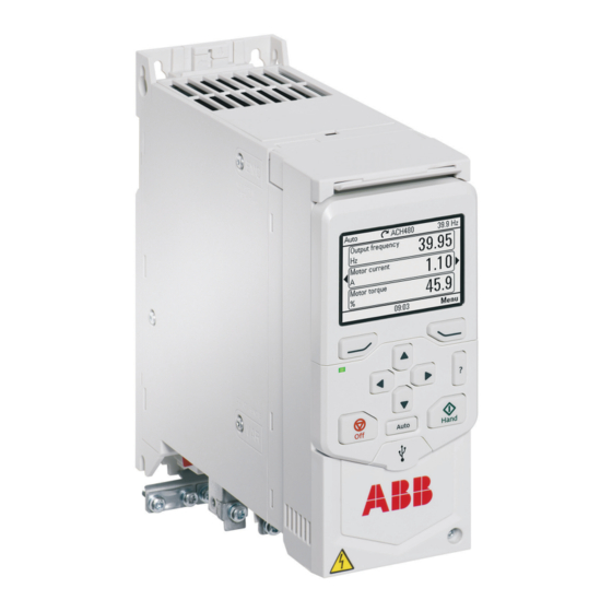
It shows a general diagram of the power connections and control interfaces. Operation principle The ACH480 is a drive for controlling asynchronous AC induction motors, permanent magnet synchronous motors and ABB synchronous reluctance motors (SynRM motors). The drive is optimized for cabinet mounting. -
Page 30: Simplified Main Circuit Diagram
■ IEC and UL (NEC) product types The ACH480 series consists of IEC product types and UL (NEC) product types. The IEC types are designed for global use. The UL (NEC) types are specifically designed for use in North America. -
Page 31: Layout
Operation principle and hardware description 31 Layout Type designation label Motor and brake resistor terminals Model information label Cooling fan Software information label Front cover Control panel connection Fixed control terminals Control panel Cold configuration connection (CCA-01) EMC filter grounding screw Option slot for communication modules Varistor grounding screw I/O or fieldbus module... -
Page 32: Control Connections
32 Operation principle and hardware description Control connections There are fixed control connections on the base unit and optional control connections on the installed option module. ■ Standard unit Connections of the base unit: 1. Auxiliary voltage outputs 2. Digital inputs 3. -
Page 33: Base Unit
Operation principle and hardware description 33 ■ Base unit Connections of the base unit: 1. Auxiliary voltage outputs 2. Digital inputs 3. Safe torque-off connections 4. Relay output connection 5. Cold configuration connection for CCA-01 6. Front option module slot 1 +24V DGND RO1C... -
Page 34: Control Panel Options
34 Operation principle and hardware description Control panel options The drive supports these control panels: • ACH-AP-H assistant hand-off-auto control panel • ACH-AP-W assistant hand-off-auto control panel with Bluetooth • RDUM-01 blank panel with RJ-45 connector • CDPI-02 panel bus adapter (blank panel with two RJ-45 connectors for the panel bus). -
Page 35: Type Designation Label
Operation principle and hardware description 35 Type designation label The type designation label is located on the left side of the drive. Example labels are shown below. Type designation label, IEC Type designation label, UL (NEC) Type designation Frame (size) Degree of protection Nominal ratings Valid markings... -
Page 36: Type Designation Key
36 Operation principle and hardware description Type designation key The type designation contains information on the specifications and configuration of the drive. Sample type code: ACH480-04-12A7-4+XXXX ■ Basic code Code Description ACH480 Product series Construction. 04 = Module, IP20 (UL open type) When there are no options selected: cabinet optimized module, IP20 (UL open type), ACH-AP-H assistant control panel, RIIO-01 I/O &... - Page 37 Operation principle and hardware description 37 Code Description K492 FPNO-21 PROFINET Documentation Full set of printed manuals in the selected language. An English manual is included, if a translation is not available. R700 English R701 German R702 Italian R703 Dutch R704 Danish R705...
-
Page 39: Mechanical Installation
Mechanical installation 39 Mechanical installation Contents of this chapter The chapter tells you how to examine the installation site, unpack, check the delivery and install the drive mechanically. Installation alternatives You can install the drive: • With screws on to a wall •... -
Page 40: Examining The Installation Site
40 Mechanical installation • You can install frames R1, R2, R3 and R4 tilted by up to 90 degrees from vertical to fully horizontal orientation. • Make sure that the hot exhaust air from a drive does not flow into the cooling inlet of other drives or equipment. -
Page 41: Unpacking The Delivery
Mechanical installation 41 Unpacking the delivery Make sure that all of the items are present and that there are no signs of damage. Standard drive package contents: • Drive • Assistant control panel (not installed) • RIIO-01 I/O & EIA-485 module (not installed) •... -
Page 42: To Install The Drive To A Din Installation Rail
42 Mechanical installation ■ To install the drive to a DIN installation rail Use an IEC/EN 60715 top hat type installation rail, width × height = 35 × 7.5 mm (1.4 × 0.3 in). 1. Move the locking part to the left. 2. - Page 43 Mechanical installation 43 6. Move the locking part to the right. 7. Make sure that the drive is correctly installed. To remove the drive, use a flat-head screwdriver to open the locking part.
-
Page 45: Guidelines For Planning The Electrical Installation
ABB does not assume any liability whatsoever for any installation which breaches the local laws and/or other regulations. Furthermore, if the recommendations given by ABB are not followed, the drive may experience problems that the warranty does not cover. -
Page 46: North America
Consider the application life time requirements. Checking the compatibility of the motor and drive Use asynchronous AC induction motor, permanent magnet synchronous motor or ABB synchronous reluctance motor (SynRM motors) with the drive. Multiple induction motors can be connected to the drive at a time when using the scalar motor control mode. -
Page 47: Typical Power Cable Sizes
Guidelines for planning the electrical installation 47 Symmetrical shielded cable reduces electromagnetic emission of the whole drive system as well as the stress on motor insulation, bearing currents and wear. Metal conduit reduces electromagnetic emission of the whole drive system. The protective conductor must always have an adequate conductivity. -
Page 48: Power Cable Types
48 Guidelines for planning the electrical installation ■ Power cable types Preferred power cable types This section presents the preferred cable types. Make sure that the selected cable type also complies with local/state/country electrical codes. Cable type Use as input power cabling Use as motor cabling Symmetrical shielded (or ar- mored) cable with three phase... -
Page 49: Alternate Power Cable Types
Guidelines for planning the electrical installation 49 Alternate power cable types Cable type Use as input power cabling Use as motor cabling Yes with phase conductor Yes with phase conductor smaller than 10 mm 2 (8 AWG) smaller than 10 mm 2 (8 AWG) Cu, or motors up to 30 kW (40 hp). -
Page 50: Not Allowed Power Cable Types
■ Additional guidelines, North America ABB recommends the use of conduit for power wiring to the drive and between the drive and the motor(s). Due to the variety of application needs, metallic and non-metallic conduit can be used. ABB prefers the use of metallic conduit. -
Page 51: Metal Conduit
Guidelines for planning the electrical installation 51 Wiring method Notes Free air Prefer symmetrical shielded VFD cable. Enclosures, air handlers, etc. Allowed internally in enclosures when in accord- ance with UL. 1) Metallic conduit may be used as an additional ground path, provided this path is a solid path capable of handling ground currents. -
Page 52: Selecting The Control Cables
■ Relay cable The cable type with braided metallic shield (for example ÖLFLEX by LAPPKABEL, Germany) has been tested and approved by ABB. ■ Control panel to drive cable Use EIA-485 with male RJ-45 connector, cable type Cat 5e or better. The maximum permitted length of the cable is 100 m (328 ft). -
Page 53: Routing The Cables
Guidelines for planning the electrical installation 53 Routing the cables ■ General guidelines – IEC • Route the motor cable away from other cables. Motor cables of several drives can be run in parallel installed next to each other. • Install the motor cable, input power cable and control cables on separate trays. -
Page 54: Continuous Motor Cable Shield/Conduit Or Enclosure For Equipment On The Motor Cable
54 Guidelines for planning the electrical installation • Use separate conduits for the input power, motor, brake resistor (optional), and control cabling. • Use separate conduit for each motor cabling. Input power cabling Motor cabling Conduit ■ Continuous motor cable shield/conduit or enclosure for equipment on the motor cable To minimize the emission level when safety switches, contactors, connection boxes or similar equipment are installed on the motor cable between the drive and the motor:... -
Page 55: Separate Control Cable Ducts
Guidelines for planning the electrical installation 55 ■ Separate control cable ducts Put 24 V DC and 230 V AC (120 V AC) control cables in separate ducts, unless the 24 V DC cable is insulated for 230 V AC (120 V AC) or insulated with an insulation sleeving for 230 V AC (120 V AC). -
Page 56: Protecting The Motor Against Thermal Overload
56 Guidelines for planning the electrical installation ■ Protecting the motor against thermal overload According to regulations, the motor must be protected against thermal overload and the current must be switched off when overload is detected. The drive includes a motor thermal protection function that protects the motor and switches off the current when necessary. -
Page 57: Protecting The Drive Against Ground Faults
Guidelines for planning the electrical installation 57 1. If there is double or reinforced insulation between the sensor and the live parts of the motor: You can connect the sensor directly to the analog/digital input(s) of the drive. See the control cable connection instructions. 2. -
Page 58: Implementing The Safe Torque Off Function
181). Using a safety switch between the drive and the motor ABB recommends to install a safety switch between the permanent magnet motor and the drive output. The switch is needed to isolate the motor from the drive during maintenance work on the drive. - Page 59 Guidelines for planning the electrical installation 59 230 V AC 230 V AC + 24 V DC Relay output Varistor RC filter Diode...
-
Page 61: Electrical Installation - Iec
Electrical installation – IEC 61 Electrical installation – IEC Contents of this chapter This chapter describes how to: • measure the insulation • do an earthing system compatibility check • change the EMC filter or ground-to-phase varistor connection • connect the power and control cables •... -
Page 62: Measuring The Insulation
Use a measuring voltage of 1000 V DC. The insulation resistance of an ABB motor must be more than 100 Mohm (reference value at 25 °C [77 °F]). For the insulation resistance of other motors, refer to the manufacturer’s instructions. -
Page 63: Measuring The Insulation Of The Brake Resistor Circuit
Electrical installation – IEC 63 U1-PE, V1-PE, W1-PE 1000 V DC, > 100 Mohm ■ Measuring the insulation of the brake resistor circuit WARNING! Obey the safety instructions of the drive. If you ignore them, injury or death, or damage to the equipment can occur. If you are not a qualified electrical professional, do not do installation or maintenance work. -
Page 64: Emc Filter
64 Electrical installation – IEC ■ EMC filter The drive has an internal EMC filter as standard. You can install the drive to a symmetrically grounded TN-S system. If you install the drive to another system, you may need to disconnect the EMC filter. See When to disconnect EMC filter or ground-to-phase varistor (page 64). - Page 65 Electrical installation – IEC 65 WARNING! Remove the metal VAR screw in IT systems. If you do not, it can cause danger or damage to the drive. Screw Screw material Earthing systems and the need to remove EMC screw or VAR label screw Symmetrically...
-
Page 66: Disconnecting The Emc Filter Or Ground-To-Phase Varistor
66 Electrical installation – IEC ■ Disconnecting the EMC filter or ground-to-phase varistor Before you continue, see When to disconnect EMC filter or ground-to-phase varistor (page 64). Obey the guidelines. 1. Do the steps in section Electrical safety precautions (page 17) before you start the work. -
Page 67: Guidelines For Installing The Drive To A Tt System
Note: • ABB does not guarantee the EMC category, because the internal EMC filter is disconnected. • ABB does not guarantee the functioning of the ground leakage detector built inside the drive. - Page 68 68 Electrical installation – IEC The table below shows the line-to-ground voltages in relation to the line-to-line voltage for each earthing system. U L-L U L1-G U L2-G U L3-G Electrical power system type Symmetrically grounded TN system (TN-S 0.58·X 0.58·X 0.58·X system)
-
Page 69: Connecting The Power Cables - Iec (Shielded Cables)
Electrical installation – IEC 69 Connecting the power cables – IEC (shielded cables) Use a symmetrical shielded power cable (VFD cable) as the motor cable. ■ Connection diagram UDC- UDC+ Disconnecting device Input power cable Two protective earth (PE) conductors, eg, fourth conductor and cable shield. According to drive safety standard IEC/EN 61800-5-1: •... -
Page 70: Connection Procedure
70 Electrical installation – IEC ■ Connection procedure WARNING! Obey the safety instructions of the drive. If you ignore them, injury or death, or damage to the equipment can occur. If you are not a qualified electrical professional, do not do installation or maintenance work. - Page 71 Electrical installation – IEC 71 8. If you use a brake resistor, connect the brake resistor cable to the R- and UDC+ terminals. Use shielded cable and ground the shield under the grounding clamp (360-degree grounding). 9. Strip the input power cable. 10.
-
Page 72: Connecting The Control Cables
72 Electrical installation – IEC Connecting the control cables Before you connect the control cables, make sure that all option modules are installed. ■ Default I/O connection diagrams (HVAC default) The connection diagrams below are valid for the standard drive variant, that is, drive equipped with the RIIO-01 I/O &... - Page 73 Electrical installation – IEC 73 Description Connection Term. Relay outputs +24V Aux. voltage output +24 V DC, max. 250 mA +24 V +24 V DGND Aux. voltage output common DGND DGND DCOM DCOM DCOM Digital input common for all RO1C Common Damper control ×...
-
Page 74: Default Fieldbus Connection Diagram
74 Electrical installation – IEC ■ Default fieldbus connection diagram The connection diagrams are valid for the base unit equipped with an optional fieldbus adapter module. Connection Description Term. Auxiliary voltage output and digital inputs +24V Aux. voltage output +24 V DC, max. 250 mA ×... -
Page 75: Control Cable Connection Procedure
Electrical installation – IEC 75 ■ Control cable connection procedure Keep the signal wire pairs twisted as near to the terminals as possible to prevent inductive coupling. WARNING! Obey the safety instructions of the drive. If you ignore them, injury or death, or damage to the equipment can occur. -
Page 76: Pnp Configuration For Digital Inputs
76 Electrical installation – IEC conductors and shield is less than 200 pF per meter (60 pF per foot). Foil or braided shields are acceptable. Drive Termination switch. Termination must be on at both ends on the fieldbus. For the drive, the termination switch position is ON. -
Page 77: Npn Configuration For Digital Inputs
Electrical installation – IEC 77 NPN configuration for digital inputs Internal and external +24 V power supply connections for NPN (sink) configuration are shown in the figure below. Internal +24 V power supply External +24 V power supply +24 V +24 V DGND +24 V DC... -
Page 78: Connection Examples Of Two-Wire And Three-Wire Sensors
78 Electrical installation – IEC Connection examples of two-wire and three-wire sensors The figures give examples of connections for a two-wire or three-wire sensor/transmitter that is supplied by the auxiliary voltage output of the drive. 4…20 mA AGND +24V DGND Process actual value measurement or reference, 0(4) …... - Page 79 Electrical installation – IEC 79 See the firmware manual for information on the related Motor thermal protection function, and the required parameter settings. PTC connection 1 1…3 PTC sensors can be connected in series to an analog input and an analog output. The analog output feeds a constant excitation current of 1.6 mA through the sensor.
-
Page 80: Ai1 And Ai2 As Pt100, Pt1000, Ni1000, Kty83 And Kty84 Sensor Inputs
80 Electrical installation – IEC +10 V DGND DCOM 1…3 PTC sensors Digital input and analog input. Set the analog input type to V (volt) in parameter group 12 Standard AI. Define the temperature sensor type, signal source, etc. with parameters 35.11…35.24. -
Page 81: Safe Torque Off
Electrical installation – IEC 81 AGND AGND 1…3 × (Pt100 or Pt1000) or 1 × (Ni1000 or KTY83 or KTY84) Analog input. Set the analog input type to V (volt) in parameter group 12 Standard AI. Define the temperature sensor type, signal source, etc. with parameters 35.11…35.24. Set the analog input type to V (volt) in parameter group 12 Standard AI. -
Page 82: Connecting A Pc
82 Electrical installation – IEC For more information on the BAPO-01 module, see BAPO-01 auxiliary power extension module (page 199). Connecting a PC You can connect a PC to the drive. To communicate with the drive, the PC must have suitable software (for example, Drive composer) installed. -
Page 83: Installing A Front Option
Electrical installation – IEC 83 ■ Installing a front option WARNING! Obey the safety instructions of the drive. If you ignore them, injury or death, or damage to the equipment can occur. If you are not a qualified electrical professional, do not do installation or maintenance work. -
Page 84: Installing A Side Option
84 Electrical installation – IEC Note: If you have the BIO-01 option module, you can add one additional fieldbus module on top of it. ■ Installing a side option WARNING! Obey the safety instructions of the drive. If you ignore them, injury or death, or damage to the equipment can occur. - Page 85 Electrical installation – IEC 85 6. Attach the grounding bar to the bottom of the side option and to the front ground tab on the drive. 7. Connect the control cables. See the control cable connection instructions.
-
Page 87: Electrical Installation - North America
Electrical installation – North America 87 Electrical installation – North America Contents of this chapter This chapter describes how to: • measure the insulation • do an earthing system compatibility check • change the EMC filter or ground-to-phase varistor connection •... -
Page 88: Measuring The Insulation
Use a measuring voltage of 1000 V DC. The insulation resistance of an ABB motor must be more than 100 Mohm (reference value at 25 °C [77 °F]). For the insulation resistance of other motors, refer to the manufacturer’s instructions. -
Page 89: Measuring The Insulation Of The Brake Resistor Circuit
Electrical installation – North America 89 U1-PE, V1-PE, W1-PE 1000 V DC, > 100 Mohm ■ Measuring the insulation of the brake resistor circuit WARNING! Obey the safety instructions of the drive. If you ignore them, injury or death, or damage to the equipment can occur. -
Page 90: Emc Filter
90 Electrical installation – North America ■ EMC filter The drive has an internal EMC filter as standard. However, for the UL(NEC) drive types, the filter is disconnected as default. The filter is typically not needed in North American installations. If you are concerned with EMC issues, and install the drive to a symmetrically grounded TN-S system, you can connect the internal EMC filter. - Page 91 Electrical installation – North America 91 WARNING! Do not install the metal EMC screw in systems other than the symmetrically grounded TN-S system. It can cause danger, or damage to the drive. Screw Factory Earthing systems and factory default EMC or VAR screw label default screw Symmetrically...
-
Page 92: Disconnecting The Ground-To-Phase Varistor, Or Connecting The Emc Filter
92 Electrical installation – North America ■ Disconnecting the ground-to-phase varistor, or connecting the EMC filter Before you continue, see When to disconnect ground-to-phase varistor, or connect EMC filter (page 90). Obey the guidelines. 1. Do the steps in section Electrical safety precautions (page 17) before you start the work. -
Page 93: Guidelines For Installing The Drive To A Tt System
Note: • ABB does not guarantee the EMC category, because the internal EMC filter is disconnected. • ABB does not guarantee the functioning of the ground leakage detector built inside the drive. -
Page 94: Connecting The Power Cables - North America (Wiring In Conduits)
Connecting the power cables – North America (wiring in conduits) Use insulated wires suitable for the installation in electric conduits. See the National Electric Code and Local ordinances. Note: ABB prefers the use of a symmetrical shielded motor cable (VFD cable). -
Page 95: Connection Diagram
Electrical installation – North America 95 ■ Connection diagram UDC+ T1/U T2/V T3/W 3 ~ M Supply disconnecting device and fuses Input power wiring Enclosure that drive is installed in Protective earth (PE) conductor(s). According to drive safety standards IEC/EN 61800-5-1 and UL 61800-5-1: •... -
Page 96: Connecting The Control Cables
96 Electrical installation – North America 3. Make sure that the conduit is correctly grounded at the cable entry. 4. Strip the conductor ends and pull the conductors through the conduits. 5. Open the locking screw of the drive front cover and lift the front cover up. 6. - Page 97 Electrical installation – North America 97 Description Connection Term. Digital inputs and auxiliary voltage output +24V × Aux. voltage output +24 V DC, max. 250 mA +24 V +24 V DGND Aux. voltage output common × DGND DGND DCOM DCOM DCOM Digital input common for all ×...
-
Page 98: Default Fieldbus Connection Diagram
98 Electrical installation – North America Description Connection Term. Auxiliary voltage input/output +24V Aux. voltage output +24 V DC, max. 250 mA +24 V DGND Aux. voltage output common DGND DCOM DCOM Digital input common for all 1) Terminal size: 0.14 … 1.5 mm 2 (26 … 16 AWG) Tightening torque: 0.5 … 0.6 N·m (4.4 … 5.3 lbf·in) 2) ×... -
Page 99: Control Cable Connection Procedure
Electrical installation – North America 99 Connection Description Term. Fieldbus connection DSUB9 +K457 FCAN-01 CANopen DSUB9 +K454 FPBA-01 Profibus DP RJ45×2 +K465 FBIP-21 BACnet/IP RJ45×2 +K469 FECA-01 EtherCAT RJ45×2 +K475 FENA-21 Ethernet/IP, Profinet, Modbus TCP See the applicable fieldbus adapter manu- RJ45×2 +K470 FEPL-02 Ethernet Powerlink Term.block... -
Page 100: Additional Information On The Control Connections
100 Electrical installation – North America ■ Additional information on the control connections Connecting EIA-485 fieldbus cable to the drive Connect the cable to the EIA-485 terminal on the RIIO-01 I/O & EIA-485 module, which is attached to the drive. The connection diagram is shown below. The EIA-485 network uses shielded, twisted-pair cable with a characteristic impedance of 100 …... -
Page 101: Pnp Configuration For Digital Inputs
Electrical installation – North America 101 PNP configuration for digital inputs Internal and external +24 V power supply connections for PNP (source) configuration are shown in the figure below. Internal +24 V power supply External +24 V power supply +24 V +24 V 0 V DC DGND... -
Page 102: Connection For Obtaining 0
102 Electrical installation – North America Connection for obtaining 0 … 10 V from analog output 2 (AO2) To obtain 0 … 10 V from analog output AO2, connect a 500 ohm resistor (or two 1 kohm resistors in parallel) between AO2 and AGND. Examples are shown in the figure below. 500 ohm 1 kohm 1 kohm... -
Page 103: Ai And Ao (Or Ai, Di And +10 V) As Ptc Motor Temperature Sensor Interface
Electrical installation – North America 103 AI and AO (or AI, DI and +10 V) as PTC motor temperature sensor interface WARNING! IEC 60664 and IEC 61800-5-1 require double or reinforced insulation between live parts and accessible parts when: • the accessible parts are not conductive, or •... -
Page 104: Ai1 And Ai2 As Pt100, Pt1000, Ni1000, Kty83 And Kty84 Sensor Inputs
104 Electrical installation – North America PTC connection 2 If no analog output is available for the PTC connection, it is possible to use a voltage divider connection. 1…3 PTC sensors are connected in series with 10 V reference and digital and analog inputs. -
Page 105: Safe Torque Off
Electrical installation – North America 105 See the firmware manual for information on the related Motor thermal protection function. AGND AGND 1…3 × (Pt100 or Pt1000) or 1 × (Ni1000 or KTY83 or KTY84) Analog input. Set the analog input type to V (volt) in parameter group 12 Standard AI. Define the temperature sensor type, signal source, etc. -
Page 106: Connecting A Pc
106 Electrical installation – North America For more information on the BAPO-01 module, see BAPO-01 auxiliary power extension module (page 199). Connecting a PC You can connect a PC to the drive. To communicate with the drive, the PC must have suitable software (for example, Drive composer) installed. -
Page 107: Installing A Front Option
Electrical installation – North America 107 ■ Installing a front option WARNING! Obey the safety instructions of the drive. If you ignore them, injury or death, or damage to the equipment can occur. If you are not a qualified electrical professional, do not do installation or maintenance work. -
Page 108: Installing A Side Option
108 Electrical installation – North America Note: If you have the BIO-01 option module, you can add one additional fieldbus module on top of it. ■ Installing a side option WARNING! Obey the safety instructions of the drive. If you ignore them, injury or death, or damage to the equipment can occur. - Page 109 Electrical installation – North America 109 6. Attach the grounding bar to the bottom of the side option and to the front ground tab on the drive. 7. Connect the control cables. See the control cable connection instructions.
-
Page 111: Installation Checklist Of The Drive
Installation checklist of the drive 111 Installation checklist of the drive Contents of this chapter This chapter contains a checklist of the mechanical and electrical installation of the drive. Checklist Examine the mechanical and electrical installation of the drive before start-up. Go through the checklist together with another person. - Page 112 112 Installation checklist of the drive Make sure that … The supply voltage matches the nominal input voltage of the drive. See the type designation label. The insulation resistance of the input power cable, motor cable and motor is measured according to local regulations.
- Page 113 Installation checklist of the drive 113 Make sure that … If a drive bypass connection will be used: The direct-on-line contactor of the motor and the drive output contactor are either mechanically and/or electrically interlocked, that is, they cannot be closed at the same time. A thermal overload device must be used for protection when bypassing the drive.
-
Page 115: Maintenance
The table below shows the maintenance tasks which can be done by the end user. The complete maintenance schedule is available on the Internet (www.abb.com/drivesservices). For more information, consult your local ABB Service representative (www.abb.com/searchchannels). Recommended annual actions by the user... -
Page 116: Cleaning The Heatsink
Performance of on/off-site work (commissioning, tests, measurements or other work) Replacement Maintenance and component replacement intervals are based on the assumption that the equipment is operated within the specified ratings and ambient conditions. ABB recommends annual drive inspections to ensure the highest reliability and optimum performance. -
Page 117: Replacing The Cooling Fans
Parameter 05.04 Fan on-time counter shows the running time of the cooling fan. After you replace the fan, reset the fan counter. Refer to the firmware manual. You can get replacement fans from ABB. Use only ABB specified spare parts. ■... - Page 118 118 Maintenance 5. Disconnect the fan power cable. 6. Free the fan clips and remove the fan from the fan cover. 7. Install the new fan into the fan cover. Make sure that the air flow is in the correct direction.
-
Page 119: To Replace The Cooling Fan For Frame R4
Maintenance 119 11. Push the cover to lock into position. ■ To replace the cooling fan for frame R4 WARNING! Obey the safety instructions of the drive. If you ignore them, injury or death, or damage to the equipment can occur. If you are not a qualified electrical professional, do not do installation or maintenance work. - Page 120 120 Maintenance 4. Lift and pull the fan from its base. 5. Disconnect the fan power cable from the extension cable connector. 6. Replace the fan. The arrow indicating the air flow direction must point up. 7. Connect the fan power cable. 8.
-
Page 121: Capacitors
Capacitor failure is usually followed by damage to the unit and an input cable fuse failure, or a fault trip. If you think that any capacitors in the drive have failed, contact ABB. ■... -
Page 123: Technical Data
Technical data 123 Technical data Contents of this chapter The chapter contains the technical specifications of the drive, such as ratings, sizes and technical requirements as well as provisions for fulfilling the requirements for CE, UL and other approval marks. Electrical ratings ■... -
Page 124: Ul (Nec) Ratings
124 Technical data IEC type Input current Output ratings ACH480- With Max. Nominal use Light-duty use 04-… choke choke current Frame I max I Ld P Ld 046A-4 56.0 45.0 68.4 45.0 22.0 42.8 22.0 050A-4 60.0 50.0 81.0 50.0 22.0 48.0 22.0... -
Page 125: Definitions
NEMA 4-pole motors (460 V, 60 Hz). ■ Sizing ABB recommends the DriveSize tool for selecting the drive, motor and gear combination (http://new.abb.com/drives/software-tools/drivesize). You can also use the ratings tables. Output derating The load capacity (I ) decreases in some situations. - Page 126 126 Technical data Example 1, IEC: How to calculate the derated current The drive type is ACH480-04-018A-4, which has a nominal output current (I ) of 17 A at 400 V. Calculate the derated output current at 4 kHz switching frequency, at 1500 m altitude and at 55 °C surrounding air temperature.
- Page 127 Technical data 127 Altitude derating: The derating factor for 1800 m is Surrounding air temperature derating: Derating is not necessary at 35 °C surrounding air temperature. To see if the derated output current of a drive is sufficient for the application, multiply the nominal output current (I ) by all the applicable derating factors.
-
Page 128: Surrounding Air Temperature Derating
128 Technical data ■ Surrounding air temperature derating Frame Temperature Derating Less than 50 °C No derating (122 °F) R1…R3 50 … 60 °C Output current decreases by 1% for every additional 1 °C (122 … 140 °F) (1.8 F). 50 …... - Page 129 Technical data 129 the derated current. Multiply the drive output current with the applicable derating factor from the table. Derating is not necessary when changing parameter 97.01 Switching frequency reference. Frame R4: If the application is cyclic and the surrounding air temperature is constantly over 40 °C (104 °F), keep parameter 97.02 Minimum switching frequency at its default value (1.5 kHz).
-
Page 130: Fuses
Make sure that the operating time of the fuse is less than 0.5 seconds. Obey the local regulations. IEC type Drive input gG fuses Min. ACH480-04- current short-circuit I 2 t Nominal Voltage ABB type current current rating 60269 size A 2 s 3-phase U N = 400 V 02A7-4 OFAF000H6 03A4-4 OFAF000H6... -
Page 131: Gr Fuses (Iec)
Technical data 131 gR fuses (IEC) IEC type Drive input gR fuses Min. ACH480-04- current short-circuit Nominal Voltage Bussmann I 2 t current current rating type 60269 size A 2 s 3-phase U N = 400 V 02A7-4 170M2694 03A4-4 170M2694 04A1-4 170M2695... -
Page 132: Ul (Nec) Fuse Alternatives
132 Technical data UL (NEC) Drive in- Fuses type put cur- Nomin- Max. fuse rating ACH480- rent Voltage al cur- for group install- Bussmann/ 04-… rating Type rent ation Edison type 034A-4 50.0 JJS/TJS80 UL class T 042A-4 60.0 JJS/TJS100 UL class T 1) Branch circuit short-circuit protection for group installation by fuses: Suitable for motor group installation on a circuit that is capable of delivering no more than 65000 rms symmetrical amperes, 480 V maximum, when... - Page 133 Technical data 133 UL (NEC) Drive Fuse UL 248-8 Fast Acting Class J Fuses type input Max. Voltage Mersen / Edison ACH480-04- current current rating Ferraz Bussmann Littelfuse Shawmut 06A0-4 11.5 JKS-20 JLS20 A4J20 JFL20 07A6-4 15.0 JKS-20 JLS20 A4J20 JFL20 011A-4 20.2...
-
Page 134: Alternate Short-Circuit Protection
The protective characteristics of the circuit breakers depend on the type, construction and settings of the breakers. There are also limitations pertaining to the short-circuit capacity of the supply network. Your local ABB representative can help you in selecting the breaker type when the supply network characteristics are known. -
Page 135: Manual Self-Protected Combination Motor Controller - Type E Usa (Ul (Nec))
Obey the manufacturer’s instructions. You can use the circuit breakers specified by ABB. You can also use other circuit breakers with the drive if they provide the same electrical characteristics. ABB does not assume any liability whatsoever for the correct function and protection of the circuit breakers not specified by ABB. - Page 136 Refer to the technical data. For UL only: The minimum enclosure volume is specified in the UL listing when applied with the ABB Type E MMP shown in the table. Fuses must be used for wall-mounted drives installed with a UL Type 1 kit.
-
Page 137: Dimensions And Weights
Technical data 137 Dimensions and weights Frame Dimensions and weights (IP20 / UL open type) Weight 1.97 7.52 2.95 7.52 5.83 7.52 10.3 9.21 7.52 12.4 Frame Dimensions and weights (UL Type 1 kit installed) Weight 11.6 1.97 7.52 11.6 2.95 7.52 13.0... -
Page 138: Free Space Requirements
138 Technical data Free space requirements Frame Free space requirement Below Above Sides 1) Drives with the optional UL Type 1 kit: 50 mm (2 in), measured from the top of the hood. 2) A side-mounted option module requires 20 mm (0.8 in) of free space on the right side of the drive. Losses, cooling data and noise Drives with frame size R1…R4 have a cooling fan. -
Page 139: Typical Power Cable Sizes
Technical data 139 UL (NEC) Heat dissipation Noise type flow Main circuit at Main and Control circuit Control circuit ACH480-04- rated current control circuit min. max. max. BTU/h BTU/h BTU/h BTU/h dB(A) 3-phase U N = 480 V 02A1-4 03A0-4 03A5-4 04A8-4 06A0-4... -
Page 140: Terminal Data For The Power Cables
140 Technical data Cable conductor sizes (mm 2 ) IEC type Frame ACH480- 04-… 050A-4 3×25 + 16 1) Size of typical power cable (symmetrical, shielded, three-phase copper cable). Note that for the input power connection, you may have to use two separate PE conductors (IEC 61800-5-1). UL (NEC) Wire size, Cu (AWG) Frame... -
Page 141: Terminal Data For The Control Cables
Technical data 141 IEC type L1, L2, L3, T1/U, T2/V, T3/W, R-, R+/ ACH480- UDC+ 04-… Minimum Maximum Tightening Minimum Maximum Tightening (solid/stran- (solid/stran- torque (solid/stran- (solid/stran- torque ded) ded) ded) ded) mm 2 mm 2 mm 2 mm 2 N·m N·m 026A-4... -
Page 142: External Emc Filters
IEC drive types. See also EMC compatibility and motor cable length compliance (IEC/EN 61800-3:2004 + A1:2012) (page 149). IEC type EMC filter type Category ACH480- ABB type code Schaffner order code 04-… 3-phase U N = 400 V 02A7-4 RFI-32 FN 3268-16-44 03A4-4... -
Page 143: Electrical Power Network Specification
(cos phi) Motor connection data Motor type Asynchronous AC induction motors, permanent magnet synchronous motors or ABB synchronous reluctance motors (SynRM motors) Voltage (U2) 0 … U1, 3-phase symmetrical Short-circuit protec- The motor output is short-circuit proof by IEC 61800-5-1 and UL 61800- tion (IEC 61800-5-1, 5-1. -
Page 144: Motor Cable Length
144 Technical data ■ Motor cable length Operational functionality and motor cable length The drive is designed to operate with optimum performance with the following maximum motor cable lengths. The values are valid for 4 kHz switching frequency. Frame Maximum motor cable length Standard drive, without external options R1, R2 R3, R4... -
Page 145: Brake Resistor Connection Data
Technical data 145 Brake resistor connection data Short-circuit protec- The brake resistor output is conditionally short-circuit proof by tion (IEC 61800-5-1, IEC/EN 61800-5-1 and UL 61800-5-1. IEC 60439-1, Rated conditional short-circuit current is as defined in IEC 60439-1. UL 61800-5-1) Control connection data The data is valid for the standard drive variant (base unit equipped with the I/O &... -
Page 146: Efficiency
146 Technical data Connector pitch 5 mm, wire size 2.5 mm 2 (14 AWG) EIA-485 embedded fieldbus (A+, B-, Physical layer: RS-485 DGND) Cable type: Shielded twisted pair cable with twisted pair for data and a wire or pair for signal ground, nominal impedance 100 … 165 ohm, for example Belden 9842 Transmission rate: 9.6 …... -
Page 147: Materials
Technical data 147 Requirement Operation installed Storage in the protect- Transportation in the for stationary use ive package protective package Relative humidity 5 … 95% Max. 95% Max. 95% No condensation permitted. Maximum permitted relative humidity is 60% in the presence of corrosive gases. Contamination levels IEC 60721-3-3: 2002 IEC 60721-3-1: 1997... -
Page 148: Applicable Standards
IEC 62635 guidelines. To aid recycling, plastic parts are marked with an appropriate identification code. Contact your local ABB distributor for further information on environmental aspects and recycling instructions for professional recyclers. End of life treatment must follow international and local regulations. -
Page 149: Emc Compliance (Iec/En 61800-3:2004 + A1:2012)
Technical data 149 UL Listed mark for USA and Canada Product has been tested and evaluated against the relevant North American standards by the Underwriters Laboratories. Valid with rated voltages up to 600 V. RCM mark Product complies with Australian and New Zealand requirements specific to EMC, telecommunications and electrical safety. -
Page 150: Category C1
150 Technical data Drive of category C1: drive of rated voltage less than 1000 V and intended for use in the first environment. Drive of category C2: drive of rated voltage less than 1000 V and intended to be installed and started up only by a professional when used in the first environment. -
Page 151: Category C3
Technical data 151 WARNING! Do not install a drive with the internal EMC filter connected to an earthing system that the EMC filter is not suitable for (for example, an IT system). The supply network becomes connected to ground potential through the internal EMC filter capacitors, which can cause danger or damage to the drive. -
Page 152: Ul Checklist
152 Technical data Drive 2. An EMC plan for preventing disturbances is drawn up for the installation. A template is available in Technical guide No. 3 EMC compliant installation and configuration for a power drive system (3AFE61348280 (English)). 3. The motor and control cables are selected as specified in this manual. For the best EMC performance, the EMC recommendations are obeyed. -
Page 153: Disclaimers
UL-compliant installations. • The input cable must be protected with UL-rated fuses, or the ABB Type E manual motor protectors (MMP) listed in this manual. The fuses or the manual motor protectors provide branch circuit protection in accordance with the National Electrical Code (NEC) and Canadian Electrical Code. -
Page 154: Cybersecurity Disclaimer
ABB and its affiliates are not liable for damages and/or losses related to such security breaches, any unauthorized access, interference, intrusion, leakage and/or... -
Page 155: Dimension Drawings
Dimension drawings 155 Dimension drawings Contents of this chapter The chapter contains the dimension drawings of the drive. The dimensions are in millimeters and inches. -
Page 156: Frame R1
156 Dimension drawings Frame R1 ■ Frame R1 (front & side) - IP20 / UL open type... -
Page 157: Frame R1 (Bottom & Rear) - Ip20 / Ul Open Type
Dimension drawings 157 ■ Frame R1 (bottom & rear) - IP20 / UL open type... -
Page 158: Frame R1 (Front & Side) - Ul Type 1 Kit Installed
158 Dimension drawings ■ Frame R1 (front & side) - UL Type 1 kit installed... -
Page 159: Frame R1 (Bottom & Rear) - Ul Type 1 Kit Installed
Dimension drawings 159 ■ Frame R1 (bottom & rear) - UL Type 1 kit installed... -
Page 160: Frame R2
160 Dimension drawings Frame R2 ■ Frame R2 (front & side) - IP20 / UL open type... -
Page 161: Frame R2 (Bottom & Rear) - Ip20 / Ul Open Type
Dimension drawings 161 ■ Frame R2 (bottom & rear) - IP20 / UL open type... -
Page 162: Frame R2 (Front & Side) - Ul Type 1 Kit Installed
162 Dimension drawings ■ Frame R2 (front & side) - UL Type 1 kit installed... -
Page 163: Frame R2 (Bottom & Rear) - Ul Type 1 Kit Installed
Dimension drawings 163 ■ Frame R2 (bottom & rear) - UL Type 1 kit installed... -
Page 164: Frame R3
164 Dimension drawings Frame R3 ■ Frame R3 (front & side) - IP20 / UL open type... -
Page 165: Frame R3 (Bottom & Rear) - Ip20 / Ul Open Type
Dimension drawings 165 ■ Frame R3 (bottom & rear) - IP20 / UL open type... -
Page 166: Frame R3 (Front & Side) - Ul Type 1 Kit Installed
166 Dimension drawings ■ Frame R3 (front & side) - UL Type 1 kit installed... -
Page 167: Frame R3 (Bottom & Rear) - Ul Type 1 Kit Installed
Dimension drawings 167 ■ Frame R3 (bottom & rear) - UL Type 1 kit installed... -
Page 168: Frame R4
168 Dimension drawings Frame R4 ■ Frame R4 (front & side) - IP20 / UL open type... -
Page 169: Frame R4 (Bottom & Rear) - Ip20 / Ul Open Type
Dimension drawings 169 ■ Frame R4 (bottom & rear) - IP20 / UL open type... -
Page 170: Frame R4 (Front & Side) - Ul Type 1 Kit Installed
170 Dimension drawings ■ Frame R4 (front & side) - UL Type 1 kit installed... -
Page 171: Frame R4 (Bottom & Rear) - Ul Type 1 Kit Installed
Dimension drawings 171 ■ Frame R4 (bottom & rear) - UL Type 1 kit installed... -
Page 173: Resistor Braking
Resistor braking 173 Resistor braking Contents of this chapter The chapter describes how to select the brake resistor and cables, protect the system, connect the brake resistor and enable resistor braking. Safety WARNING! Do not do work on the brake resistor or the resistor cable when the drive is energized. - Page 174 174 Resistor braking 4. Select the resistor so that the following conditions are met: • The rated power of the resistor must be greater than or equal to P Rmax • Resistance R must be between R and R given in the table for the used drive type.
-
Page 175: Reference Brake Resistors
Resistor braking 175 ■ Reference brake resistors IEC type Example resistor R min R max P BRcont P BRmax ACH480- types 04-… Danotherm 3-phase U N = 400 V 02A7-4 0.55 0.75 0.83 1.10 CBH 360 C T 406 210R 03A4-4 0.75 1.00... -
Page 176: Definitions
IGBT semiconductors of the brake chopper. Note: ABB has not verified that the EMC requirements are fulfilled with custom brake resistors and cabling. The customer must consider the EMC compliance of the complete installation. -
Page 177: Protecting The System In Brake Circuit Fault Situations
An example wiring diagram is shown below. ABB recommends that you use resistors equipped with a thermal switch (1) inside the resistor assembly. The switch... -
Page 178: Mechanical And Electrical Installation Of Brake Resistor
178 Resistor braking ABB recommends that you also wire the thermal switch to a digital input of the drive, and configure the input to cause a fault trip at resistor overtemperature indication. Θ +24V Drive input power connection with a main contactor... -
Page 179: Electrical Installation
Resistor braking 179 ■ Electrical installation Measuring the insulation See the electrical installation instructions of the drive. Connecting power cables See the electrical installation instructions of the drive. Connection the control cables Connect the thermal switch of the brake resistor as described in Protecting the system against thermal overload (page 177). -
Page 181: The Safe Torque Off Function
The Safe torque off function 181 The Safe torque off function Contents of this chapter This chapter describes the Safe torque off (STO) function of the drive and gives instructions for its use. Description The Safe torque off function can be used, for example, as the final actuator device of safety circuits that stop the drive in case of danger (such as an emergency stop circuit). -
Page 182: Compliance With The European Machinery Directive
182 The Safe torque off function Standard Name IEC 61000-6-7:2014 Electromagnetic compatibility (EMC) – Part 6-7: Generic stand- ards – Immunity requirements for equipment intended to perform functions in a safety-related system (functional safety) in indus- trial locations IEC 61326-3-1:2017 Electrical equipment for measurement, control and laboratory use –... -
Page 183: Wiring
The Safe torque off function 183 Wiring For the electrical specifications of the STO connection, see the technical data of the control unit. ■ Connection principle Single ACH480 drive, internal power supply + 24 V DC OUT1 SGND UDC+ UDC- Drive Control unit Control logic... -
Page 184: Single Ach480 Drive, External Power Supply
184 The Safe torque off function Single ACH480 drive, external power supply 24 V DC OUT1 + 24 V DC SGND UDC+ UDC- Drive Control unit Control logic To motor Activation switch... -
Page 185: Wiring Examples
The Safe torque off function 185 ■ Wiring examples Single ACH480 drive, internal power supply OUT1 SGND Drive Safety PLC Safety relay Single ACH480 drive, external power supply 24 V DC OUT1 SGND ÍN2 Drive Safety PLC Safety relay... -
Page 186: Multiple Ach480 Drives, Internal Power Supply
186 The Safe torque off function Multiple ACH480 drives, internal power supply OUT1 +24 V SGND OUT1 SGND OUT1 SGND Drive Control unit Activation switch... -
Page 187: Multiple Ach480 Drives, External Power Supply
The Safe torque off function 187 Multiple ACH480 drives, external power supply 24 V DC – OUT1 +24 V SGND OUT1 SGND OUT1 SGND Drive Control unit Activation switch ■ Activation switch In the wiring diagrams, the activation switch has the designation [K]. This represents a component such as a manually operated switch, an emergency stop push button switch, or the contacts of a safety relay or safety PLC. -
Page 188: Cable Types And Lengths
188 The Safe torque off function • In case a manually operated activation switch is used, the switch must be of a type that can be locked out to the open position. • The contacts of the switch or relay must open/close within 200 ms of each other. ■... -
Page 189: Operation Principle
The Safe torque off function 189 Operation principle 1. The Safe torque off activates (the activation switch is opened, or safety relay contacts open). 2. The STO inputs of the drive control unit de-energize. 3. The control unit cuts off the control voltage from the output IGBTs. 4. -
Page 190: Start-Up Including Acceptance Test
190 The Safe torque off function Start-up including acceptance test To ensure the safe operation of a safety function, validation is required. The final assembler of the machine must validate the function by performing an acceptance test. The acceptance test must be performed •... - Page 191 The Safe torque off function 191 Action Test the operation of the STO function when the motor is stopped. • Give a stop command for the drive (if running) and wait until the motor shaft is at a standstill. Make sure that the drive operates as follows: •...
-
Page 192: Use
192 The Safe torque off function 1. Open the activation switch, or activate the safety functionality that is wired to the STO connection. 2. The STO inputs on the drive control unit de-energize, and the control unit cuts off the control voltage from the output IGBTs. 3. -
Page 193: Maintenance
If any wiring or component change is needed after start up, or the parameters are restored, do the test given in section Acceptance test procedure (page 190). Use only spare parts approved by ABB. Record all maintenance and proof test activities in the machine logbook. ■ Competence... -
Page 194: Fault Tracing
See the firmware manual of the drive control program for the indications generated by the drive, and for details on directing fault and warning indications to an output on the control unit for external diagnostics. Any failures of the Safe torque off function must be reported to ABB. -
Page 195: Safety Data
The Safe torque off function 195 Safety data The safety data for the Safe torque off function is given below. Note: The safety data is calculated for redundant use, and does not apply if both STO channels are not used. PFD avg PFD avg Frame... -
Page 196: Abbreviations
196 The Safe torque off function • STO fault indication (parameter 31.22) delay: < 500 ms • STO warning indication (parameter 31.22) delay: < 1000 ms ■ Abbreviations Abbr. Reference Description Cat. EN ISO 13849-1 Classification of the safety-related parts of a control system in respect of their resistance to faults and their subsequent behavior in the fault condition, and which is achieved by the structural arrangement of the parts, fault detection and/or by... -
Page 197: Tüv Certificate
After the mission time elapses, the safety device must be replaced. Note that any T M values given cannot be regarded as a guarantee or warranty. ■ TÜV certificate The TÜV certificate is available on the Internet at www.abb.com/drives/documents. -
Page 198: Declaration Of Conformity
198 The Safe torque off function ■ Declaration of conformity... -
Page 199: Bapo-01 Auxiliary Power Extension Module
BAPO-01 auxiliary power extension module 199 BAPO-01 auxiliary power extension module Contents of this chapter This chapter contains a description and technical data of the optional BAPO-01 auxiliary power extension module. Safety instructions WARNING! Obey the safety instructions of the drive. If you ignore them, injury or death, or damage to the equipment can occur. -
Page 200: Layout
200 BAPO-01 auxiliary power extension module ■ Layout 1. BAPO-01 module 2. Locking screw hole 3. Internal X100 connector 4. Internal X102 connector 5. Grounding rail Mechanical installation See the electrical installation instructions of the drive. Electrical installation Connect the external power supply to the +24 V and DGND terminals on the drive. See the electrical installation instructions of the drive. -
Page 201: Start-Up
BAPO-01 auxiliary power extension module 201 BAPO-01 24VDC (+) +24V GND (-) DGND External power supply Drive +24 V internal Main power supply +5 V internal Start-up To configure the BAPO-01 module: 1. Power up the drive. 2. Set the parameter 95.04 Control board supply to 1 (External 24V). Technical data Voltage and current rating for the auxiliary power supply: +24 V DC ±10%, max. - Page 202 202 BAPO-01 auxiliary power extension module Dimensions: 26 [1.024] 11.3 [0.444] 86.1 [3.391] 16 [0.63] 2.5 [0.098] 42.2 [1.662] 13.3 [0.524] 52.5 [2.067 68.5 [2.697]...
-
Page 203: Bio-01 I/O Extension Module
BIO-01 I/O extension module 203 BIO-01 I/O extension module Contents of this chapter This chapter contains a description and technical data of the optional BIO-01 I/O extension module. Safety instructions WARNING! Obey the safety instructions of the drive. If you ignore them, injury or death, or damage to the equipment can occur. -
Page 204: Layout
204 BIO-01 I/O extension module ■ Layout 1. Locking tab 2. Option module slot 3. Chassis screw 4. I/O connector Mechanical installation See the electrical installation instructions of the drive. Before you install the BIO-01 option module, make sure that the chassis screw slider is in the top position. -
Page 205: Start-Up
BIO-01 I/O extension module 205 Connection Terminal Description +24 V Auxiliary voltage output +24 V DC, max. 250 mA × DGND Auxiliary voltage output common × +24 V +24 V DCOM Digital input common for all × DGND DGND Stop (0) / Start (1) ×... - Page 206 206 BIO-01 I/O extension module Dimensions...
-
Page 207: Brel-01 Relay Output Extension Module
BREL-01 relay output extension module 207 BREL-01 relay output extension module Contents of this chapter This chapter contains a description and technical data of the optional BREL-01 relay output extension module. Safety instructions WARNING! Obey the safety instructions of the drive. If you ignore them, injury or death, or damage to the equipment can occur. -
Page 208: Layout
Product overview BREL-01 relay output extension module (option +L511) adds four relay outputs to the 208 BREL-01 relay output extension module drive. Layout ■ Layout 1. BREL module 1. BREL-01 module 2. Locking screw hole 2. Locking screw hole 3. -
Page 209: Start-Up
BREL-01 relay output extension module 209 Identification Description X103 Output relays 4…7: Max. switching voltage: 250 V AC / 30 V DC Common Max. switching current: 2 A Normally closed Galvanically isolated. Normally open X104 Common Normally closed Normally open X105 Common Normally closed... - Page 210 210 BREL-01 relay output extension module Name/Value Description Def / FbEq16/32 Bit 0 RO4 1 = Relay output 4 is ON. Bit 1 RO5 1 = Relay output 5 is ON. Bit 2 RO6 1 = Relay output 6 is ON. Bit 3 RO7 1 = Relay output 7 is ON.
-
Page 211: Technical Data
BREL-01 relay output extension module 211 Name/Value Description Def / FbEq16/32 0.0 … 3000.0 s Activation delay for RO5. 10 = 1 s 15.12 RO5 OFF delay Defines the deactivation delay for relay output RO5. 0.0 s 0.0 … 3000.0 s Deactivation delay for RO5. - Page 212 212 BREL-01 relay output extension module Dimensions: 3AXD50000031148 rev. A...
-
Page 213: Further Information
Product and service inquiries Address any inquiries about the product to your local ABB representative, quoting the type designation and serial number of the unit in question. A listing of ABB sales, support and service contacts can be found by navigating to www.abb.com/searchchannels. - Page 214 3AXD50000245949B © 2020 ABB. All rights reserved. Specifications subject to change without notice.