Table of Contents
Advertisement
SERVICE MANUAL
Ver 1.0 2003.02
AUDIO POWER SPECIFICATIONS
POWER OUTPUT AND TOTAL HARMONIC
DISTORTION:
With 6 ohm loads, from 28 – 200 Hz; rated 80 watts, minimum RMS
power, with no more than 0.8 % total harmonic distortion from 250
milliwatts to rated output.
System
Type
Active Subwoofer (magnetically shielded design)
Speaker unit
Woofer: 20 cm dia. (8 in.), cone type
Amplifier section
Continuous RMS output : (0.8%) 80W
Reproduction frequency range
28 Hz – 200 Hz
High frequency cut-off frequency
50 Hz – 200 Hz
Phase selector
NORMAL, REVERSE
Inputs
Input jacks
INPUT: input pin jack
SPEAKER IN: input terminals
Output jacks
SPEAKER OUT: output terminals
Sony Corporation
9-877-108-01
Home Audio Company
2003B0200-1
Published by Sony Engineering Corporation
© 2003.02
SA-WM200
SPECIFICATIONS
General
Power requirements
USA and Canada models: 120 V AC, 60 Hz
Other models: 220-230V AC, 50/60 Hz
Power consumption
100 W
Dimensions
Approx. 270 x 325 x 398 mm
3
7
(10
/
x 12
/
x 15
4
8
Mass
10 kg (22 lb 1oz)
Supplied accessories
Foot pads (4)
Audio connecting cord (1 phono – 1 phono),
2 m (6 ft 6
1
/
in.) (1)
2
Speaker cords, 2.5 m (8 ft 2
Design and specifications are subject to change without notice.
US Model
Canadian Model
AEP Model
UK Model
E Model
11
/
in.) (w/h/d)
16
1
/
in.) (2)
2
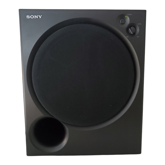
ACTIVE SUBWOOFER
Advertisement
Table of Contents

Related Manuals for Sony SA-WM200


Summary of Contents for Sony SA-WM200
-
Page 1: Specifications
Design and specifications are subject to change without notice. Phase selector NORMAL, REVERSE Inputs Input jacks INPUT: input pin jack SPEAKER IN: input terminals Output jacks SPEAKER OUT: output terminals ACTIVE SUBWOOFER Sony Corporation 9-877-108-01 Home Audio Company 2003B0200-1 Published by Sony Engineering Corporation © 2003.02... -
Page 2: Table Of Contents
SONY PARTS WHOSE PART NUMBERS APPEAR AS FONCTIONNEMENT. NE REMPLACER CES COMPOSANTS SHOWN IN THIS MANUAL OR IN SUPPLEMENTS PUB- QUE PAR DES PIÈCES SONY DONT LES NUMÉROS SONT LISHED BY SONY. DONNÉS DANS CE MANUEL OU DANS LES SUPPLÉMENTS... -
Page 3: General
SA-WM200 SECTION 1 SECTION 2 GENERAL DIAGRAMS This section is extracted from instruction manual. THIS NOTE IS COMMON FOR PRINTED WIRING BOARDS AND SCHEMATIC DIAGRAMS. • Location of controls (In addition to this, the necessary note is printed in each block.) For Schematic Diagrams. -
Page 4: Printed Wiring Boards - Main Section
SA-WM200 2-2. PRINTED WIRING BOARDS – MAIN Section – See page 3 for Notes. See page 3 for Circuit Boards Location. CONTROL BOARD LEVEL INPUT INPUT POWER SWITCH CONTROL CONTROL SP901 BOARD BOARD BOARD BOARD SPEAKER (Page 6) (Page 6) -
Page 5: Printed Wiring Boards - Input Control Section
SA-WM200 2-3. PRINTED WIRING BOARDS – INPUT CONTROL Section – See page 3 for Notes. See page 3 for Circuit Boards Location. MAIN MAIN BOARD BOARD (Page 4) (Page 4) INPUT CONTROL BOARD CUT OFF FREQ 1-686-985- (11) PHASE NORMAL... -
Page 6: Printed Wiring Boards - Power Section
SA-WM200 2-4. PRINTED WIRING BOARDS – POWER Section – See page 3 for Notes. See page 3 for Circuit Boards Location. MAIN BOARD POWER TRANS BOARD (Page 4) POWER TRANSFORMER SWITCH BOARD MAIN BOARD (Page 4) POWER POWER 1-686-986- 1-686-984-... -
Page 7: Schematic Diagram - Main Section (1/2)
SA-WM200 2-5. SCHEMATIC DIAGRAM – MAIN SECTION (1/2) – See page 3 for Notes. -
Page 8: Schematic Diagram - Main Section (2/2)
SA-WM200 2-6. SCHEMATIC DIAGRAM – MAIN SECTION (2/2) – See page 3 for Notes. -
Page 9: Exploded Views
(US,CND) 4-999-482-01 KNOB (VOL) 4-243-834-21 PANEL, FRONT (AEP,UK,MY,SP) 4-985-341-01 SCREW (US,CND) 0 F901 4-998-417-02 EMBLEM (NO.5), SONY 1-532-463-51 FUSE (T1AL 250V) (AEP,UK,MY,SP) 4-973-938-83 KNOB (A), PUSH (SILVER) 4-973-938-93 KNOB (A), PUSH (BLACK) 0 F901 1-532-744-11 FUSE, GLASS TUBE (2.5A 125V) (US,CND) -
Page 10: Electrical Parts List
SA-WM200 SECTION 4 CONTROL ELECTRICAL PARTS LIST INPUT CONTROL MAIN When indicating parts by reference num- NOTE : ber, please include the board. • Items marked “ * ”are not stocked since they • Due to standardization, replacements in the are seldom required for routine service. - Page 11 SA-WM200 MAIN POWER TRANS SWITCH Ref. No. Part No. Description Remark Ref. No. Part No. Description Remark C309 1-136-165-00 FILM 0.1uF R215 1-249-429-11 CARBON 1/4W C310 1-136-165-00 FILM 0.1uF R217 1-249-441-11 CARBON 100K 1/4W C311 1-162-199-31 CERAMIC 10PF R301 1-249-425-11 CARBON 4.7K...
- Page 12 SA-WM200 SWITCH Ref. No. Part No. Description Remark < CONNECTOR > 1-564-321-00 PIN, CONNECTOR(3.96MM PITCH)2P CN901 1-564-517-11 PLUG, CONNECTOR 2P < DIODE > D901 8-719-057-10 DIODE LNJ301MPUJAB (POWER) < SWITCH > 0 S901 1-554-920-11 SWITCH, PUSH (AC POWER)(1 KEY) (POWER)
- Page 13 SA-WM200 MEMO...
- Page 14 SA-WM200 REVISION HISTORY Clicking the version allows you to jump to the revised page. Also, clicking the version at the upper right on the revised page allows you to jump to the next revised page. Ver. Date Description of Revision...