HP ProLiant DL380 Gen9 Maintenance And Service Manual
Hide thumbs
Also See for ProLiant DL380 Gen9:
- User manual (215 pages) ,
- Maintenance and service manual (142 pages) ,
- Maintenance and service manual (128 pages)
Table of Contents
Advertisement
Quick Links
HP ProLiant DL380 Gen9 Server
Maintenance and Service Guide
Abstract
This guide describes identification and maintenance procedures, diagnostic tools, specifications, and requirements for hardware components and
software. This guide is for an experienced service technician. HP assumes you are qualified in the servicing of computer equipment, trained in
recognizing hazards in products, and are familiar with weight and stability precautions.
Part Number: 768831-001
September 2014
Edition: 1
Advertisement
Table of Contents

Related Manuals for HP ProLiant DL380 Gen9


Summary of Contents for HP ProLiant DL380 Gen9
- Page 1 This guide describes identification and maintenance procedures, diagnostic tools, specifications, and requirements for hardware components and software. This guide is for an experienced service technician. HP assumes you are qualified in the servicing of computer equipment, trained in recognizing hazards in products, and are familiar with weight and stability precautions.
- Page 2 © Copyright 2014 Hewlett-Packard Development Company, L.P. The information contained herein is subject to change without notice. The only warranties for HP products and services are set forth in the express warranty statements accompanying such products and services. Nothing herein should be construed as constituting an additional warranty. HP shall not be liable for technical or editorial errors or omissions contained herein.
-
Page 3: Table Of Contents
Extend the server from the rack ......................27 Remove the server from the rack ......................27 Access the product rear panel ......................28 Access the optional HP Systems Insight Display ................... 28 Release the full-length expansion board retainer .................. 29 Safety considerations ..........................30 Preventing electrostatic discharge ...................... - Page 4 Secure Boot configuration ......................... 89 Embedded UEFI shell ........................90 Embedded Diagnostics option ......................90 HP RESTful API support for UEFI ......................90 Re-entering the server serial number and product ID ................90 HP ProLiant Pre-boot Health Summary ......................91 HP Insight Diagnostics ..........................
- Page 5 HP 500W Flex Slot Platinum Hot-plug Power Supply ................113 HP 800W Flex Slot Platinum Hot-plug Power Supply ................113 HP 1400W Flex Slot Platinum Plus Hot-plug Power Supply ..............114 Acronyms and abbreviations ...................... 115 Documentation feedback ......................117 Index ............................
-
Page 6: Customer Self Repair
HP specifies in the materials shipped with a replacement CSR part whether a defective part must be returned to HP. In cases where it is required to return the defective part to HP, you must ship the defective part back to HP within a defined period of time, normally five (5) business days. The defective part must be returned with the associated documentation in the provided shipping material. - Page 7 HP sono realizzati con numerosi componenti che possono essere riparati direttamente dal cliente (CSR, Customer Self Repair). Se in fase di diagnostica HP (o un centro di servizi o di assistenza HP) identifica il guasto come riparabile mediante un ricambio CSR, HP lo spedirà direttamente al cliente per la sostituzione.
- Page 8 La mancata restituzione del componente può comportare la fatturazione del ricambio da parte di HP. Nel caso di riparazione da parte del cliente, HP sostiene tutte le spese di spedizione e resa e sceglie il corriere/vettore da utilizzare.
- Page 9 Si, durante la fase de diagnóstico, HP (o los proveedores o socios de servicio de HP) identifica que una reparación puede llevarse a cabo mediante el uso de un componente CSR, HP le enviará dicho componente directamente para que realice su sustitución. Los componentes CSR se clasifican en dos categorías:...
- Page 10 HP podrá cobrarle por el de sustitución. En el caso de todas sustituciones que lleve a cabo el cliente, HP se hará cargo de todos los gastos de envío y devolución de componentes y escogerá la empresa de transporte que se utilice para dicho servicio.
- Page 11 Opcional – Peças cujo reparo feito pelo cliente é opcional. Essas peças também são projetadas para o reparo feito pelo cliente. No entanto, se desejar que a HP as substitua, pode haver ou não a cobrança de taxa adicional, dependendo do tipo de serviço de garantia destinado ao produto.
- Page 12 No caso desse serviço, a substituição de peças CSR é obrigatória. Se desejar que a HP substitua essas peças, serão cobradas as despesas de transporte e mão-de-obra do serviço. Customer self repair 12...
- Page 13 Customer self repair 13...
- Page 14 Customer self repair 14...
- Page 15 Customer self repair 15...
-
Page 16: Illustrated Parts Catalog
Illustrated parts catalog Mechanical components HP continually improves and changes product parts. For complete and current supported parts information, see one of the following websites: • HP PartSurfer website (http://partsurfer.hp.com) • HP PartSurfer mobile site (http://partsurfermobile.hp.com) Item Description Spare part number... - Page 17 Optional—Parts for which customer self repair is optional. These parts are also designed for customer self repair. If, however, you require that HP replace them for you, there may or may not be additional charges, depending on the type of warranty service designated for your product.
- Page 18 Optional: Opcional—Peças cujo reparo feito pelo cliente é opcional. Essas peças também são projetadas para o reparo feito pelo cliente. No entanto, se desejar que a HP as substitua, pode haver ou não a cobrança de taxa adicional, dependendo do tipo de serviço de garantia destinado ao produto.
-
Page 19: System Components
System components HP continually improves and changes product parts. For complete and current supported parts information, see one of the following websites: • HP PartSurfer website (http://partsurfer.hp.com) Illustrated parts catalog 19... - Page 20 • HP PartSurfer mobile site (http://partsurfermobile.hp.com) Item Description Spare part number Customer self repair (on page 6) System components DIMMs — — a) 8-GB, 1Rx4, PC4-2133R 774170-001 Mandatory b) 16-GB, 2Rx4, PC4-2133R* 774172-001 Mandatory c) 32-GB, 32-GB, 4Rx4, PC4-2133L* 774174-001...
- Page 21 Mandatory c) 1400 W, Flex Slot Platinum* 754383-001 Mandatory System I/O board assembly 775400-001 Optional FlexibleLOM — — a) HP InfiniBand FDR 2-port, 5450-QSFP Adapter 705087-001 Mandatory b) HP InfiniBand FDR 2-port, 545FLR-QSFP 705088-001 Mandatory Adapter* Drives Hot-plug drives —...
- Page 22 Item Description Spare part number Customer self repair (on page 6) l) 6-TB, SAS, LFF, 7,200-rpm, 6G* 761497-001 Mandatory m) 500-GB, SATA, LFF, 7,200-rpm, 6G* 658103-001 Mandatory n) 1-TB, SATA, SFF, 7,200-rpm, 6G* 656108-001 Mandatory o) 1-TB, SATA, LFF, 7,200-rpm, 6G* 657739-001 Mandatory p) 2-TB, SATA, LFF, 7,200-rpm, 6G*...
- Page 23 HP Smart Array P440ar Controller* 749796-001 Optional HP H240ar HBA* 749997-001 Optional HP SmartArray P840 Controller* 761880-001 Optional HP 12Gb DL380 Gen9 SAS Expander Card 761879-001 Optional HP NVIDIA Quadro K2200 3GB GPU* 783874-001 Optional HP NVIDIA Quadro K4200 4GB GPU* 783875-001 Optional...
- Page 24 Optional—Parts for which customer self repair is optional. These parts are also designed for customer self repair. If, however, you require that HP replace them for you, there may or may not be additional charges, depending on the type of warranty service designated for your product.
- Page 25 Optional: Opcional—Peças cujo reparo feito pelo cliente é opcional. Essas peças também são projetadas para o reparo feito pelo cliente. No entanto, se desejar que a HP as substitua, pode haver ou não a cobrança de taxa adicional, dependendo do tipo de serviço de garantia destinado ao produto.
-
Page 26: Removal And Replacement Procedures
Extend the server from the rack (on page 27). If you are performing service procedures in an HP, Compaq branded, telco, or third-party rack cabinet, you can use the locking feature of the rack rails to support the server and gain access to internal components. -
Page 27: Extend The Server From The Rack
The sliding rails could pinch your fingers. Remove the server from the rack To remove the server from an HP, Compaq branded, telco, or third-party rack: Power down the server (on page 26). -
Page 28: Access The Product Rear Panel
Open the cable management arm. The cable management arm can be right-mounted or left-mounted. Access the optional HP Systems Insight Display To access a pop-out HP Systems Insight Display on models with this option installed: Press and release the panel. -
Page 29: Release The Full-Length Expansion Board Retainer
After the display fully ejects, rotate the display to view the LEDs. Release the full-length expansion board retainer To remove the component: Power down the server (on page 26). Remove all power: Disconnect each power cord from the power source. Disconnect each power cord from the server. -
Page 30: Safety Considerations
Release the full-length expansion board retainer. To replace the component, reverse the removal procedure. Safety considerations Before performing service procedures, review all the safety information. Preventing electrostatic discharge To prevent damaging the system, be aware of the precautions you need to follow when setting up the system or handling parts. -
Page 31: Server Warnings And Cautions
This symbol indicates the presence of electric shock hazards. The area contains no user or field serviceable parts. Do not open for any reason. WARNING: To reduce the risk of injury from electric shock hazards, do not open this enclosure. This symbol on an RJ-45 receptacle indicates a network interface connection. -
Page 32: Air Baffle
WARNING: To reduce the risk of personal injury from hot surfaces, allow the drives and the internal system components to cool before touching them. CAUTION: Do not operate the server for long periods with the access panel open or removed. Operating the server in this manner results in improper airflow and improper cooling that can lead to thermal damage. -
Page 33: Pcie Riser Blank
Remove the air baffle. To replace the component, reverse the removal procedure. PCIe riser blank CAUTION: To prevent improper cooling and thermal damage, do not operate the server unless all PCI slots have either an expansion slot cover or an expansion board installed. To remove the component: Power down the server (on page 26). -
Page 34: Primary Pcie Riser Cage
Remove the PCIe riser blank. To replace the component, reverse the removal procedure. Primary PCIe riser cage WARNING: To reduce the risk of personal injury, electric shock, or damage to the equipment, remove the power cord to remove power from the server. The front panel Power On/Standby button does not completely shut off system power. -
Page 35: Secondary Pcie Riser Cage
Remove the PCIe riser cage. To replace the component, reverse the removal procedure. Secondary PCIe riser cage WARNING: To reduce the risk of personal injury, electric shock, or damage to the equipment, remove the power cord to remove power from the server. The front panel Power On/Standby button does not completely shut off system power. -
Page 36: Pcie Riser Board
Remove the secondary PCIe riser cage. To replace the component, reverse the removal procedure. PCIe riser board To remove the component: Power down the server (on page 26). Remove all power: Disconnect each power cord from the power source. Disconnect each power cord from the server. Do one of the following: Extend the server from the rack (on page 27). -
Page 37: Drive Blank
Remove the PCIe riser board. To replace the component, reverse the removal procedure. Drive blank CAUTION: To prevent improper cooling and thermal damage, do not operate the server unless all bays are populated with either a component or a blank. To remove the component: Remove the drive blank. -
Page 38: Power Supply Blank
Remove the drive. To replace the component, reverse the removal procedure. Power supply blank Remove the component as indicated. To replace the component, reverse the removal procedure. AC power supply CAUTION: To prevent improper cooling and thermal damage, do not operate the server unless all bays are populated with either a component or a blank. -
Page 39: Optical Drive
WARNING: To reduce the risk of personal injury from hot surfaces, allow the power supply or power supply blank to cool before touching it. To replace the component, reverse the removal procedure. Optical drive To remove the component: Power down the server (on page 26). Remove all power: Disconnect each power cord from the power source. - Page 40 Disconnect the optical drive cable. Remove the optical drive. Removal and replacement procedures 40...
- Page 41 Remove the optical drive bracket, for use with the replacement optical drive. Before replacing the component, install the optical drive bracket, retained from the optical drive you are replacing. To replace the component, reverse the removal procedure. Removal and replacement procedures 41...
-
Page 42: Hot-Plug Fan
Hot-plug fan To remove the component: Power down the server (on page 26). Remove all power: Disconnect each power cord from the power source. Disconnect each power cord from the server. Do one of the following: Extend the server from the rack (on page 27). Remove the server from the rack (on page 27). -
Page 43: Flexiblelom
Do one of the following: Extend the server from the rack (on page 27). Remove the server from the rack (on page 27). Remove the access panel ("Access panel" on page 31). Remove the fan cage. CAUTION: Do not operate the server for long periods with the access panel open or removed. Operating the server in this manner results in improper airflow and improper cooling that can lead to thermal damage. -
Page 44: 8-Sff Drive Cage
Remove the FlexibleLOM. To replace the component, reverse the removal procedure. 8-SFF drive cage To remove the component: Power down the server (on page 26). Remove all power: Disconnect each power cord from the power source. Disconnect each power cord from the server. Do one of the following: Extend the server from the rack (on page 27). -
Page 45: 3-Lff Rear Drive Cage
Remove the drive cage. To replace the component, reverse the removal procedure. 3-LFF rear drive cage To remove the component: Power down the server (on page 26). Remove all power: Disconnect each power cord from the power source. Disconnect each power cord from the server. Do one of the following: Extend the server from the rack (on page 27). -
Page 46: 2-Sff Rear Drive Cage
Remove the drive cage. To replace the component, reverse the removal procedure. 2-SFF rear drive cage To remove the component: Power down the server (on page 26). Remove all power: Disconnect each power cord from the power source. Disconnect each power cord from the server. Do one of the following: Extend the server from the rack (on page 27). -
Page 47: 2-Sff Front Drive Cage
Remove the drive cage. To replace the component, reverse the removal procedure. 2-SFF front drive cage To remove the component: Power down the server (on page 26). Remove all power: Disconnect each power cord from the power source. Disconnect each power cord from the server. Do one of the following: Extend the server from the rack (on page 27). -
Page 48: Universal Media Bay
Remove the drive cage. To replace the component, reverse the removal procedure. Universal media bay To remove the component: Power down the server (on page 26). Remove all power: Disconnect each power cord from the power source. Disconnect each power cord from the server. Do one of the following: Extend the server from the rack (on page 27). -
Page 49: 8-Sff Drive Backplane
Remove the universal media bay. To replace the component, reverse the removal procedure. 8-SFF drive backplane To remove the component: Power down the server (on page 26). Remove all power: Disconnect each power cord from the power source. Disconnect each power cord from the server. Do one of the following: Extend the server from the rack (on page 27). -
Page 50: 2-Sff Rear Drive Backplane
Remove the drive backplane. To replace the component, reverse the removal procedure. 2-SFF rear drive backplane To remove the component: Power down the server (on page 26). Remove all power: Disconnect each power cord from the power source. Disconnect each power cord from the server. Do one of the following: Extend the server from the rack (on page 27). -
Page 51: 12-Lff Drive Backplane
Remove the drive backplane. To replace the component, reverse the removal procedure. 12-LFF drive backplane To remove the component: Power down the server (on page 26). Remove all power: Disconnect each power cord from the power source. Disconnect each power cord from the server. Do one of the following: Extend the server from the rack (on page 27). -
Page 52: 4-Lff Drive Backplane
Remove the drive backplane. To replace the component, reverse the removal procedure. 4-LFF drive backplane To remove the component: Power down the server (on page 26). Remove all power: Disconnect each power cord from the power source. Disconnect each power cord from the server. Do one of the following: Extend the server from the rack (on page 27). -
Page 53: 3-Lff Rear Drive Backplane
Remove the drive backplane. To replace the component, reverse the removal procedure. 3-LFF rear drive backplane To remove the component: Power down the server (on page 26). Remove all power: Disconnect each power cord from the power source. Disconnect each power cord from the server. Do one of the following: Extend the server from the rack (on page 27). -
Page 54: Systems Insight Display
Remove the drive backplane. To replace the component, reverse the removal procedure. Systems Insight Display To remove the component: Power down the server (on page 26). Remove all power: Disconnect each power cord from the power source. Disconnect each power cord from the server. Do one of the following: Extend the server from the rack (on page 27). -
Page 55: Expansion Slot Blanks
Remove the screw securing the Systems Insight Display, and then remove the Systems Insight Display. To replace the component, reverse the removal procedure. Expansion slot blanks WARNING: To reduce the risk of personal injury, electric shock, or damage to the equipment, remove the power cord to remove power from the server. -
Page 56: Expansion Boards
Primary PCIe riser cage Optional primary PCIe riser cage Secondary PCIe riser cage To replace the component, reverse the removal procedure. Expansion boards Full length expansion board WARNING: To reduce the risk of personal injury, electric shock, or damage to the equipment, remove the power cord to remove power from the server. -
Page 57: Half-Length Expansion Board
To remove the component: Power down the server (on page 26). Remove all power: Disconnect each power cord from the power source. Disconnect each power cord from the server. Disconnect any external cables that are connected to the expansion board. Do one of the following: Extend the server from the rack (on page 27). -
Page 58: Heatsink
Disconnect each power cord from the power source. Disconnect each power cord from the server. Disconnect any external cables that are connected to the expansion board. Do one of the following: Extend the server from the rack (on page 27). Remove the server from the rack (on page 27). - Page 59 Remove the server from the rack (on page 27). Remove the access panel ("Access panel" on page 31). Remove the air baffle ("Air baffle" on page 32). Remove the heatsink. To replace the component: Remove the thermal interface protective cover from the heatsink. Removal and replacement procedures 59...
-
Page 60: Processor
1866MHz, or 2133MHz. To remove the component: Update the system ROM. Locate and download the latest ROM version from the HP website (http://www.hp.com/support). Follow the instructions on the website to update the system ROM. Power down the server (on page 26). - Page 61 Remove the server from the rack (on page 27). Remove the access panel ("Access panel" on page 31). Remove the heatsink ("Heatsink" on page 58). Open each of the processor locking levers in the order indicated, and then open the processor retaining bracket.
- Page 62 Install the processor. Verify that the processor is fully seated in the processor retaining bracket by visually inspecting the processor installation guides on either side of the processor. THE PINS ON THE SYSTEM BOARD ARE VERY FRAGILE AND EASILY DAMAGED. CAUTION: THE PINS ON THE SYSTEM BOARD ARE VERY FRAGILE AND EASILY DAMAGED.
-
Page 63: Dimms
Press and hold the processor retaining bracket in place, and then close each processor locking lever. Press only in the area indicated on the processor retaining bracket. Align and install the heatsink. Install the access panel ("Access panel" on page 31). DIMMs IMPORTANT: This server does not support mixing RDIMMs and UDIMMs. -
Page 64: Hp Smart Storage Battery
32). Remove the DIMM. To replace the component, reverse the removal procedure. For DIMM configuration information, see the server user guide. HP Smart Storage Battery To remove the component: Power down the server (on page 26). Remove all power: Disconnect each power cord from the power source. -
Page 65: Hp Flexible Smart Array Controller
To replace the component, reverse the removal procedure. HP Flexible Smart Array Controller CAUTION: HP recommends performing a complete backup of all server data before performing a controller or adapter installation or removal. To remove the component: Power down the server (on page 26). -
Page 66: System Battery
Remove the controller. To replace the component, reverse the removal procedure. System battery If the server no longer automatically displays the correct date and time, you may need to replace the battery that provides power to the real-time clock. WARNING: The computer contains an internal lithium manganese dioxide, a vanadium pentoxide, or an alkaline battery pack. -
Page 67: System Board
Remove the battery. To replace the component, reverse the removal procedure. For more information about battery replacement or proper disposal, contact an authorized reseller or an authorized service provider. System board To remove the component: Power down the server (on page 26). Remove all power: Disconnect each power cord from the power source. - Page 68 Remove the system board, using the handle to lift it out of the chassis. To replace the component: Install the spare system board. Removal and replacement procedures 68...
- Page 69 Open each of the processor locking levers in the order indicated in the following illustration, and then open the processor retaining bracket. Remove the clear processor socket cover. Retain the processor socket cover for future use. CAUTION: THE PINS ON THE SYSTEM BOARD ARE VERY FRAGILE AND EASILY DAMAGED. To avoid damage to the system board, do not touch the processor or the processor socket contacts.
- Page 70 Install the processor. Verify that the processor is fully seated in the processor retaining bracket by visually inspecting the processor installation guides on either side of the processor. THE PINS ON THE SYSTEM BOARD ARE VERY FRAGILE AND EASILY DAMAGED. Close the processor retaining bracket.
- Page 71 Press and hold the processor retaining bracket in place, and then close each processor locking lever. Press only in the area indicated on the processor retaining bracket. Install the processor socket cover onto the processor socket of the failed system board. Clean the old thermal grease from the heatsink and the top of the processor with the alcohol swab.
- Page 72 Install the heatsink. IMPORTANT: Install all components with the same configuration that was used on the failed system board. Install all components removed from the failed system board. Install the access panel. Install the power supplies ("AC power supply" on page 38). Power up the server.
-
Page 73: Hp Trusted Platform Module
If you suspect a TPM board failure, leave the TPM installed and remove the system board ("System board" on page 67). Contact an HP authorized service provider for a replacement system board and TPM board. Removal and replacement procedures 73... -
Page 74: Cabling
Cabling Two-bay SFF drive cage option cabling 2 SFF drive bay option rear installation Connect the power cable: • Single cable connection with 12 LFF drive configuration in the front Cabling 74... - Page 75 • Y cable connection with 24 SFF drive configuration in front Connect the data cable: • Connected to the onboard x4 SATA connector Cabling 75...
- Page 76 • Connected to the x2 SATA port and optical disk drive connector • Connected to a PCI expansion board Cabling 76...
- Page 77 • Connected to a PCI expansion board and the 12 LFF drive backplane • Connected to an HP 12G SAS Expander Card Cabling 77...
-
Page 78: Three-Bay Lff Rear Drive Cage Cabling
Three-bay LFF rear drive cage cabling Connect the power cable. Connect the data cable: • Connected to onboard SATA connectors Cabling 78... - Page 79 • Connected to a PCI expansion board • Connected to a PCI expansion board and the 12 LFF drive backplane Cabling 79...
-
Page 80: Eight-Bay Sff Front Drive Cage Cabling
• Connected to an HP 12G SAS Expander Card Eight-bay SFF front drive cage cabling Bay 1 installation Connect the power cable: • Single cable connection Cabling 80... - Page 81 • Y cable connection if the two-bay SFF drive cage option is installed in the rear bay Connect the data cable: Cabling 81...
- Page 82 • Connected to a PCI expansion board Cabling 82...
- Page 83 • Connected to an HP 12G SAS Expander Card Bay 2 installation Cabling 83...
- Page 84 Connect the power cable. Connect the data cable: • Connected to a PCI expansion board Cabling 84...
- Page 85 • Connected to an HP 12G SAS Expander Card Cabling 85...
-
Page 86: Universal Media Bay Cabling
Universal media bay cabling Connect the VGA cable to the optional VGA connector. Connect the USB cable to the front dual internal USB 3.0 connector. Cabling 86... -
Page 87: 150W Pcie Power Cable Option
Connect the SATA optical drive cable to the front optical disk drive connector. 150W PCIe power cable option CAUTION: To prevent damage to the server or expansion boards, power down the server and remove all AC power cords before removing or installing the PCI expansion cage. Cabling 87... -
Page 88: Diagnostic Tools
Diagnostic tools HP UEFI System Utilities The HP UEFI System Utilities is embedded in the system ROM. The UEFI System Utilities enable you to perform a wide range of configuration activities, including: • Configuring system devices and installed options •... -
Page 89: Flexible Boot Control
OS installation if the defaults are restored. To avoid this issue, use the User Defined Defaults feature in UEFI System Utilities to override the factory default settings. For more information, see the HP UEFI System Utilities User Guide for HP ProLiant Gen9 Servers on the HP website (http://www.hp.com/go/ProLiantUEFI/docs). -
Page 90: Embedded Uefi Shell
Embedded UEFI shell The system BIOS in all HP ProLiant Gen9 servers includes an Embedded UEFI Shell in the ROM. The UEFI Shell environment provides an API, a command line prompt, and a set of CLIs that allow scripting, file manipulation, and system information. -
Page 91: Hp Proliant Pre-Boot Health Summary
HP ProLiant Pre-boot Health Summary If the server does not power on, you can use HP iLO to display diagnostic information on an external monitor. This feature is supported on servers that support external video and have a UID button. When power is available to the server but the server is not powered on, iLO runs on auxiliary power and can take control of the server video adapter to display the HP ProLiant Pre-boot Health Summary. -
Page 92: Active Health System
HP Active Health System does not parse or change operating system data from third-party error event log activities, such as content created or passed through by the operating system. The data that is collected is managed according to the HP Data Privacy policy. For more information see the HP website (http://www.hp.com/go/privacy). -
Page 93: Integrated Management Log
OS through the appropriate USB device drivers. Before the OS loads, HP provides support for USB 2.0 devices through legacy USB support, which is enabled by default in the system ROM. USB 3.0 ports are not functional before the OS loads. The native OS provides USB 3.0 support through appropriate xHCI drivers. -
Page 94: Troubleshooting
• Simplified Chinese (http://www.hp.com/support/Gen9_TSG_zh_cn) The HP ProLiant Gen9 Troubleshooting Guide, Volume II: Error Messages provides a list of error messages and information to assist with interpreting and resolving error messages on ProLiant servers and server blades. To view the guide, select a language: •... -
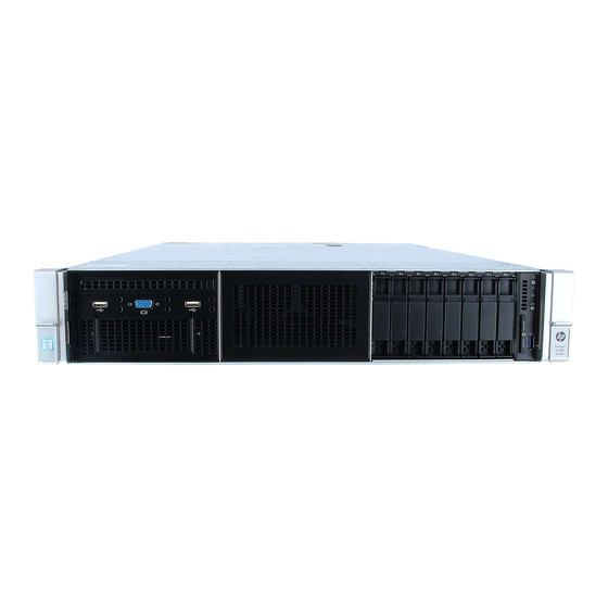
Page 95: Component Identification
Component identification Front panel components • SFF model (8-drive) Item Description Bay 1 (optional drives or optical drive, video, USB) Bay 2 (optional drives) Fixed drive bays Front USB 3.0 connector Serial label pull tab • SFF model (24-drive) Item Description Bay 1 Bay 2... - Page 96 • LFF model (12-drive) Item Description Drive bays 1-12 • LFF model (4-drive) Item Description Drive bays Component identification 96...
-
Page 97: Front Panel Leds And Buttons
Front panel LEDs and buttons • SFF front panel LEDs and button Item Description Status Power On/Standby button Solid green = System on and system power LED* Flashing green (1 Hz/cycle per sec) = Performing power on sequence Solid amber = System in standby Off = No power present** Health LED* Solid green = Normal... -
Page 98: Power Fault Leds
• LFF LEDs and button Item Description Status Health LED* Solid green = Normal Flashing green (1 Hz/cycle per sec) = iLO is rebooting Flashing amber = System degraded Flashing red (1 Hz/cycle per sec) = System critical** Power On/Standby button Solid green = System on and system power LED* Flashing green (1 Hz/cycle per sec) = Performing power on sequence... -
Page 99: Systems Insight Display Leds
8 flashes Power backplane or storage backplane 9 flashes Power supply Systems Insight Display LEDs The HP Systems Insight Display LEDs represent the system board layout. The display enables diagnosis with the access panel installed. Item Description Status NIC link/activity Off = No link to network. -
Page 100: Systems Insight Display Led Combinations
Item Description Status All other LEDs Off = Normal — Amber = Failure For more information on the activation of these LEDs, see "Systems Insight Display LED combinations (on page 100)." Systems Insight Display LED combinations When the health LED on the front panel illuminates either amber or red, the server is experiencing a health event. -
Page 101: Rear Panel Components
Health LED Status Systems Insight Display System power LED and color addition — Amber Standby Power cap (off) — Flashing green Waiting for power Power cap (green) — Green Power is available. Power cap (green) — Amber Power is not available. Power cap (flashing amber) IMPORTANT:... -
Page 102: Rear Panel Leds
Rear panel LEDs Item Description Status UID LED Off = Deactivated Solid blue = Activated Flashing blue = System being managed remotely NIC link LED Off = No network link Green = Network link NIC activity LED Off = No network activity Solid green = Link to network Flashing green = Network activity Power supply 2... -
Page 103: System Board Components
• Installing the riser cages listed in the table above in either the primary or secondary riser connectors determines the form factor of the PCI expansion boards supported by those riser cages. • FL/FH denotes full-length, full-height. HL/FH denotes half-length, full-height. System board components Item Description... -
Page 104: System Maintenance Switch
Backplane presence detect connector Optical/SATA port 5 SATA port 4 Front power/USB 3.0 connector Drive backplane power connector HP Smart Storage Battery connector Optional Location Discovery Services connector Micro SD card slot Dual internal USB 3.0 connector Smart Array/HBA connector... -
Page 105: Nmi Functionality
To force the OS to invoke the NMI handler and generate a crash dump log, the administrator can use the iLO Virtual NMI feature. For more information, see the HP website (http://www.hp.com/support/NMI). DIMM slot locations DIMM slots are numbered sequentially (1 through 12) for each processor. The supported AMP modes use the letter assignments for population guidelines. -
Page 106: Sas And Sata Device Numbers
SAS and SATA device numbers • SFF 8-device bay numbering • SFF 8-device bay numbering with SAS expander solution used • Optional SFF 16-device bay numbering • Optional SFF 16-device bay numbering with SAS expander solution used Component identification 106... - Page 107 • Optional 24 SFF device bay numbering • Optional 24 SFF device bay numbering with SAS expander solution used • LFF 12-device bay numbering • LFF 12-device bay number with 2-bay rear SAS expander solution used Component identification 107...
-
Page 108: Hot-Plug Drive Led Definitions
• LFF 12-device bay number with 3-bay rear SAS expander solution used • LFF 4-device bay numbering Hot-plug drive LED definitions Item Status Definition Locate Solid blue The drive is being identified by a host application. Flashing blue The drive carrier firmware is being updated or requires an update. Activity ring Rotating green Drive activity... -
Page 109: Hot-Plug Fans
To avoid damage to the equipment, do not operate the server for extended periods of time if the server does not have the optimal number of fans installed. Although the server might boot, HP does not recommend operating the server without the required fans installed and operating. - Page 110 • At POST and in the OS, HP iLO performs an orderly shutdown if a cautionary temperature level is detected. If the server hardware detects a critical temperature level before an orderly shutdown occurs, the server performs an immediate shutdown.
-
Page 111: Specifications
40°C to 45°C (104°F to 113°F) at sea level with an altitude derating of 1.0°C per every 125 m (1.8°F per every 410 ft) above 900 m (2953 ft) to a maximum of 3048 m (10,000 ft). The approved hardware configurations for this system are listed on the HP website (http://www.hp.com/servers/ASHRAE). -
Page 112: Power Supply Specifications
HP 500W Flex Slot Platinum Hot-plug Power Supply (on page 113) • HP 800W Flex Slot Platinum Hot-plug Power Supply (on page 113) • HP 1400W Flex Slot Platinum Plus Hot-plug Power Supply (on page 114) For detailed power supply specifications, see the HP website (http://www.hp.com/go/proliant/powersupply). Specifications 112... -
Page 113: Hp 500W Flex Slot Platinum Hot-Plug Power Supply
HP 500W Flex Slot Platinum Hot-plug Power Supply Specification Value Input requirements 100 to 120 VAC Rated input voltage 200 to 240 VAC 240 VDC for China only 50 Hz to 60 Hz Rated input frequency 5.8 A at 100 VAC Rated input current 2.8 A at 200 VAC... -
Page 114: Hp 1400W Flex Slot Platinum Plus Hot-Plug Power Supply
HP 1400W Flex Slot Platinum Plus Hot-plug Power Supply Specification Value Input requirements 200 to 240 VAC Rated input voltage 50 Hz to 60 Hz Rated input frequency 8.0 A at 200 VAC Rated input current 6.7 A at 240 VAC... -
Page 115: Acronyms And Abbreviations
Factory Integrated Option FlexibleLOM for rack servers FLR-SFP FlexibleLOM for rack servers with an SFP+ connector HP SIM HP Systems Insight Manager Integrated Lights-Out Integrated Management Log large form factor NEBS Network Equipment-Building System nonmaskable interrupt... - Page 116 NVRAM nonvolatile memory PCIe Peripheral Component Interconnect Express POST Power-On Self Test quad data rate RBSU ROM-Based Setup Utility serial attached SCSI SATA serial ATA small form factor small form-factor pluggable Trusted Platform Module unit identification universal serial bus Acronyms and abbreviations 116...
-
Page 117: Documentation Feedback
Documentation feedback HP is committed to providing documentation that meets your needs. To help us improve the documentation, send any errors, suggestions, or comments to Documentation Feedback (mailto:docsfeedback@hp.com). Include the document title and part number, version number, or the URL when submitting your feedback. -
Page 118: Index
LEDs 97 CSR (customer self repair) 6, 16 heatsink 58 customer self repair (CSR) 6, 16 hot-plug fans 28, 109 HP Insight Diagnostics 91 HP technical support 6 diagnostic tools 88, 91 diagnostics utility 91 DIMM slot locations 105... - Page 119 Systems Insight Display LEDs 99, 100 maintenance 26 management tools 88 technical support 6 mechanical components 16 tools 26 mechanical specifications 111 TPM (Trusted Platform Module) 73 troubleshooting 94 optical drive 39, 95 USB connector 95 USB support 93 part numbers 16 utilities 88 PCI expansion slots 102 PCIe riser blank 33...