Sony SLV-D370P Service Manual
Dvd player/ video cassette recorder
Hide thumbs
Also See for SLV-D370P:
- Operating instructions manual (133 pages) ,
- Service manual (120 pages) ,
- Specifications (2 pages)
Table of Contents
Advertisement
Quick Links
SERVICE MANUAL
System
Laser
Semiconductor laser
Format
VHS NTSC standard
Video recording system
Rotary head helical scanning FM system
Video heads
Double azimuth four heads
Video signal
NTSC color, EIA standards
Tape speed
3
SP: 33.35 mm/s (1
inches/s)
8
7
EP: 11.12 mm/s (
inches/s)
16
11
LP: 16.67 mm/s (
inches/s),
16
playback only
Maximum recording/playback time
8 hrs. in EP mode (with T-160 tape)
Rewind time
Approx. 1 min (with T-120 tape)
Tuner section
Channel coverage
VHF 2 to 13
UHF 14 to 69
CATV A-8 to A-1, A to W, W+1 to W+84
Antenna
75-ohm antenna terminal for VHF/UHF
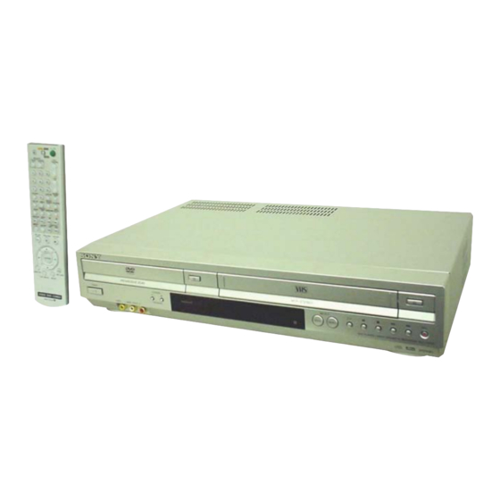
SLV-D271P/D370P
Photo: SLV-D370P
SPECIFICATIONS
Inputs and outputs
LINE IN 1 and LINE-2 IN
VIDEO IN, phono jack (1 each)
Input signal: 1 Vp-p, 75 ohms, unbalanced, sync
negative
AUDIO IN, phono jacks (2 each)
Input level: 327 mVrms
Input impedance: more than 47 kilohms
LINE OUT
VIDEO OUT, phono jack (1)
Output signal: 1 Vp-p, 75 ohms, unbalanced, sync
negative
AUDIO OUT, phono jacks (2)
Standard output: 327 mVrms
Load impedance: 47 kilohms
Output impedance: less than 10 kilohms
DIGITAL OUT
COAXIAL, phono jack
Output signal: 0.5 Vp-p, 75 ohms
COMPONENT VIDEO OUT (Y, Pb, Pr)
Phono jack
Y: 1.0 Vp-p/Pb, Pr: 0.7 Vp-p, 75 ohms
S-VIDEO OUT
4-pin, mini-DIN jack
Y: 1.0 Vp-p, unbalanced, sync negative
C: 0.286 Vp-p, load impedance 75 ohms
Timer section
Clock
Quartz locked
Timer indication
12-hour cycle
Timer setting
8 programs (max.)
Refer to the SERVICE MANUAL of VHS MECHANI-
CAL ADJUSTMENT MANUAL VII for MECHANICAL
ADJUSTMENTS. (9-921-790-11)
General
Power requirements
120 V AC, 60 Hz
Power consumption
25 W
Power back-up
Back-up duration: 0 min
Operating temperature
0°C to 45°C (32°F to 113°F)
Storage temperature
–20°C to 60°C (–4°F to 140°F)
Operating humidity
25% to 80%
Dimensions including projecting parts and controls
(w/h/d)
Approx. 430 × 85 × 287 mm
(Approx. 17 × 3
3
Mass
Approx. 3.6 kg (Approx. 7.9 lbs)
Supplied accessories
Remote commander (1)
Size AA (R6) batteries (2)
75-ohm coaxial cable with F-type connectors (1)
Design and specifications are subject to change without
notice.
VIDEO CASSETTE RECORDER
RMT-V501E
US Model
DX-13 MECHANISM
× 11
3
inches)
8
8
DVD PLAYER/
Advertisement
Table of Contents

Related Manuals for Sony SLV-D370P


Summary of Contents for Sony SLV-D370P
-
Page 1: Specifications
SLV-D271P/D370P RMT-V501E SERVICE MANUAL US Model DX-13 MECHANISM Photo: SLV-D370P Refer to the SERVICE MANUAL of VHS MECHANI- CAL ADJUSTMENT MANUAL VII for MECHANICAL ADJUSTMENTS. (9-921-790-11) SPECIFICATIONS General System Inputs and outputs Power requirements Laser LINE IN 1 and LINE-2 IN... - Page 2 LINE WITH MARK 0 ON THE SCHEMATIC DIAGRAMS AND IN THE PARTS LIST ARE CRITICAL TO SAFE OPERATION. REPLACE THESE COMPONENTS WITH SONY PARTS WHOSE PART NUMBERS APPEAR AS SHOWN IN THIS MANUAL OR IN SUPPLEMENTS PUBLISHED BY SONY. — 2 —...
-
Page 3: Table Of Contents
TABLE OF CONTENTS Precautions DVD Deck 2-6-1 Holder Chuck Removal ················································ 2-22 Safety Precautions ······························································ 4 2-6-2 Tray Disc Removal ······················································· 2-23 Servicing Precautions ························································ 6 2-6-3 Ass’y P/U Deck Removal ············································ 2-24 ESD Precautions ································································· 7 2-6-4 Ass’y Housing Removal ··············································· 2-25 Handling the Optical Pick-up ·············································... -
Page 4: Safety Precautions
PRECAUTIONS 1 SAFETY PRECAUTIONS 1) Before returning an instrument to the customer, always make a (4) Insulation Resistance Test Cold Check-(1) Unplug the power safety check of the entire instrument, including, but not limited supply cord and connect a jumper wire between the two prongs to, the following items: of the plug. - Page 5 6) Product Safety Notice-Some electrical and mechanical parts have special safety-related characteristics which are often not evident from visual inspection, nor can the protection they give necessarily be obtained by replacing them with components rated for higher voltage, wattage, etc. Parts that have special safety characteristics are identified by shading, an ( ) or a ( ) on...
-
Page 6: Servicing Precautions
2 SERVICING PRECAUTIONS CAUTION: Before servicing units covered by this service manual and its supplements, read and follow the Safety Precautions section of this manual. Note: If unforseen circumstances create conflict between the following servicing precautions and any of the safety precautions, always follow the safety precautions. -
Page 7: Esd Precautions
3 ESD PRECAUSIONS Electrostatically Sensitive Devices (ESD) Some semiconductor (solid state) devices can be damaged easily by static electricity. Such components commonly are called Electrostatically Sensitive Devices (ESD). Examples of typical ESD devices are integrated circuits and some field-effect transistors and semiconductor chip components. -
Page 8: Handling The Optical Pick-Up
4 HANDLING THE OPTICAL PICK-UP The laser diode in the optical pick up may suffer electrostatic breakdown because of potential static electricity from clothing and your body. The following method is recommended. (1) Place a conductive sheet on the work bench (The black sheet used for wrapping repair parts.) (2) Place the set on the conductive sheet so that the chassis is grounded to the sheet. -
Page 9: Pick-Up Disassembly And Reassembly
5 PICK-UP DISASSEMBLY AND REASSEMBLY 5-1 Disassembly 5-2 Assembly 1) Replace the Pick-up. 1) Remove the power cord. 2) Remove the soldering 2 points on Pick-up. 2) Disassemble the Deck-Assy. 3) Reassemble the Deck-Assy. 3) Make solder land 2 points short on Pick-up. (See Fig. - Page 10 MEMO — 10 —...
-
Page 11: General
SLV-D271P/D370P 1. GENERAL This section is extracted from instruction manual. (2-671-544-11) Region code Notes about DVD+RWs/ About this manual This player can play the DVD+Rs, DVD-RWs/DVD-Rs or following discs Your player has a region code printed on the back CD-Rs/CD-RWs of the unit and only will play DVD VIDEO discs •... - Page 12 (+) end clicks into position. The remote commander is preprogrammed to control non-Sony TVs. If your TV is listed in the Reattach the cover after inserting the battery. following table, set the appropriate manufacturer’s code number.
- Page 13 Audio/video (A/V) hookup Hookup 1 (Plug and Play) A Use this hookup if you are using: If your TV has audio/video (A/V) input jacks, you will get better picture and sound if you hook up your DVD-VCR using these connections. If your TV does not have A/V inputs, see the •...
- Page 14 Hookup 2 Step 4 : Selecting a language Use this hookup if you are connecting a cable box with many scrambled channels You can change the on-screen display language. SET UP What you can do with this hookup • Record any channel by selecting the channel on the cable box Before you start…...
- Page 15 Notes Press V/v to select “Auto”, then press • The clock cannot be set automatically if you do not receive a channel that carries a time ENTER. signal in your area. If so, set the clock manually (page 24). • If there are only a few channels in your area that carry time signals, setting the clock automatically may take up to about 20 minutes.
-
Page 16: Advanced Hookups
Press V/v to select “Channel Setup”, then Presetting/disabling channels manually press ENTER. Before you start… The “CHANNEL SETUP” menu appears. • Turn on the DVD-VCR and your TV. When using a cable box, turn it on. • Set the TV to video input so that the signal CH +/–... -
Page 17: Basic Operations
AUse this hookup if your TV has an S-VIDEO input jack A/V Receiver hookup Connect an S-VIDEO cord (not supplied). You will enjoy high quality images. BUse this hookup if your TV has component video input jacks Connect a component video cord (not supplied) or three video cords (not supplied) of the same kind and length. - Page 18 Press H PLAY. Press Locate a point quickly on the remote (or hold down on the The disc tray closes and the unit) DVD player starts playback. The playback speed changes as follows each time you press The display window shows the the button on the remote (or depending on how long you press playback time the button on the unit):...
-
Page 19: Playing A Tape
To playback the desired title/track or chapter Notes • The display may not change as operated depending on the disc. You can playback the desired title/track or chapter using • The display window continue indicating the playing time even when the counter position this menu. -
Page 20: Recording Tv Programs
To use the time counter Adjusting the picture (tracking) Press CLEAR at the point on the tape that you want to find later. The counter in the display window resets to “0:00:00.” To search for the counter 0:00:00 point Although the VCR automatically adjusts the tracking when automatically, see “Searching using various functions”... - Page 21 To watch another TV program while recording Recording TV programs using the timer Set TV / DVD·VIDEO switch to DVD·VIDEO on the remote. Press TV/VIDEO to display “TV” in the display window. You can preset up to eight programs at a time.
-
Page 22: Dvd Settings And Adjustments
Press V/v to select setting you want to change Checking/changing/canceling timer or cancel. • To change the setting, press B/b to select settings the item you want to change, and press V/v to change it. Before you start… • To cancel the setting, press CLEAR. •... -
Page 23: Screen Setup
Press B/b to select an item. Screen Setup “Screen Setup” allows you to set the screen according to the playback and connection SET UP conditions. Press SET UP to exit the menu. Before you start… • Set TV / DVD·VIDEO switch to Menu choices DVD·VIDEO on the remote. -
Page 24: Setting The Display Or Sound Track
Press SET UP to exit the menu. Setting the display or sound track language You can set various languages for the disc’s menu, sound track or subtitle. SET UP To cancel the “Progressive” setting Before you start… Select “ ” in step 2. •... -
Page 25: Dvd Additional Operations
To change the password Press b to set the parental control. Select “Change Password” in step 4 on page 63. • If you have not entered a password The display for entering a new password appears. The display for registering a new password Enter a new 4-digit password using the number buttons. -
Page 26: Changing The Angles
Changing the angles Displaying the subtitle If subtitles are recorded on the disc, you can If various angles (multi-angles) for a scene change the subtitles or turn them on and off are recorded on the DVD VIDEO, “ ” whenever you want while playing a DVD. appears in the display window. -
Page 27: Changing The Sound
Press B/b to select “PROGRAM”, then press ENTER. Playing in random order (Shuffle play) You can shuffle the playback order of tracks. Subsequent “shuffling” may produce a different playing order. To shuffle MP3 audio tracks, see page 81. Press V/v/B/b to select the track number you want to Press SELECT DVD to control the DVD player. -
Page 28: Virtual Surround Setting
Notes • To enjoy Dolby Digital or DTS effect from a LinearPCM format disc, you have to make the Virtual surround setting connection using DIGITAL AUDIO OUT (COAXIAL) (page 32). • When you play a DVD with DTS sound tracks, set “DTS” to “On” in “AUDIO SETUP” menu (page 54). - Page 29 To turn off the display Press V/v to select “MP3”, then press Repeat mode Press x STOP twice, then press O RETURN repeatedly. ENTER. Elapsed playing time The first track starts playing. Press x STOP if Notes • Only the letters in the alphabet and numbers can be used for album or track names. Anything necessary.
-
Page 30: Playing Jpeg Image Files
Tips • If you add numbers (01, 02, 03, etc.) to the front of the track file names, the tracks will be Playing JPEG image files played in that order. • A disc with many trees takes longer to start playback. Some discs with many trees cannot be played back. -
Page 31: Vcr Additional Operations
About JPEG image files Playing VIDEO CDs with “PBC ON/OFF” You can play back DATA CDs (CD-ROMs/CD-Rs/CD-RWs) or DATA DVDs (DVD-ROMs/ Functions DVD+RWs/DVD+Rs/DVD-RWs/DVD-Rs) recorded in JPEG format. However, the discs must be recorded according to ISO9660 Level 1/Level 2 or Joliet format and DATA DVDs of Universal Disk Format (UDF) for the player to recognize the tracks (or files). -
Page 32: Searching Using Various Functions
Recording stereo and bilingual programs Searching using various functions The VCR automatically marks the tape with an index signal at the point where each recording begins. Recording stereo programs SELECT VIDEO You can easily find a specific point using various search functions. When you receive a program broadcast in stereo, press AUDIO to display “Hi-Fi”... -
Page 33: Additional Information
Press B/b to change the setting. Editing with another VCR How to connect to record on this VCR Press SET UP to exit the menu. This VCR (Recorder) Menu choices The default settings are indicated in bold print. LINE-2 IN Menu option Set this option to Tape Length... -
Page 34: Troubleshooting
Symptom Remedy There is no picture/picture noise • Re-connect the connecting cord securely. If you have any questions or problems not covered below, please consult your nearest Sony appears. • The connecting cords are damaged. dealer. (For customers in USA) •... - Page 35 • The video heads are dirty (see “On cleaning the video The JPEG image file cannot be • The DATA CD or DATA DVD is not recorded in JPEG heads” (page 3)). Clean the video heads using a Sony played. format that conforms to ISO9660 Level 1/Level 2 or video head cleaning cassette.
-
Page 36: Index To Parts And Controls
DVD-RW (page 7) Index to parts and controls A DVD-RW is a recordable and rewritable disc that is the same size as a DVD VIDEO. The DVD-RW has two different modes: Refer to the pages indicated in parentheses ( ) for details. VR mode and Video mode. - Page 37 F SET UP button (20) Remote commander for VIDEO DVD Audio/Subtitle Language G TIMER button (48) H AUDIO button* (91) Abbreviation Language SKIP button (42) Arabic REPLAY button (42) Bulgarian K SP (Standard Play)/EP (Extended Play) Chinese button (46) Croatian L z REC (record) button (46) Czech Danish...
- Page 38 MEMO 1-28E...
-
Page 39: Disassembly And Reassembly
SLV-D271P/D370P 2. DISASSEMBLY AND REASSEMBLY 2-1 CABINET AND PCB 2-1-1 Cabinet Top Removal 2-1-3 Ass’y Front Panel Removal 2 Lift up the Cabinet Top in the direction of arrow. 1 RELEASE 3 HOOKS 1 REMOVE (Top View) 3 SCREWS (3 X 10B) Fig. -
Page 40: Chassis Removal
2-1-5 Chassis Removal 2 REMOVE 4 SCREWS 1 REMOVE 2 SCREWS (4 X 12Y) (3 X 12Y) 3 REMOVE 3 SCREWS (3 X 12Y) VCR DECK 4 REMOVE 3 SCREWS DVD DECK 5 REMOVE 2 SCREWS DVD MAIN PCB VCR MAIN PCB FUNCTION TIMER PCB 6 REMOVE 1 SCREW Fig. -
Page 41: Circuit Board Locations
2-2 CIRCUIT BOARD LOCATIONS DVD MAIN PCB VCR MAIN PCB FUNCTION TIMER PCB Fig. 2-7 Circuit Board Locations... -
Page 42: Vcr Deck Parts Locations
2-3 VCR DECK PARTS LOCATIONS 2-3-1 Top View Fig. 2-8 Top parts Location-1 1 GEAR FL CAM 2 ASS’Y MOTOR LOADING 3 ASS’Y LEVER ARM 4 ASS’Y HOLDER CASSETTE 5 LEVER FL DOOR 6 SLIDER FL DRIVE... - Page 43 qa 0 qs Fig. 2-9 Top Parts Location-2 1 FE HEAD 8 DISK S REEL 2 ASS’Y CYLINDER 9 ASS’Y LEVER S BRAKE 3 ASS’Y ACE HEAD 0 GEAR IDLE 4 ASS’Y LEVER UNIT PINCH qa LEVER IDLE 5 ASS’Y LEVER #9 GUIDE qs ASS’Y LEVER T BRAKE 6 ASS’Y LEVER TENSION qd DISK T REEL...
-
Page 44: Bottom View
2-3-2 Bottom View Fig. 2-10 Bottom Parts Location 1 GEAR JOINT 1 2 GEAR JOINT 2 3 BRAKET GEAR 4 ASS’Y MOTOR CAPSTAN 5 ASS’Y LEVER T LOAD 6 GEAR LOADING DRIVE 7 ASS’Y LEVER S LOAD 8 ASS’Y CLUTCH 9 BELT PULLEY 0 SLIDER CAM... -
Page 45: Vcr Deck
2-4 VCR DECK 2-4-1 Ass’y Holder Cassette Removal 2-4-2 Ass’y Lever Arm Removal 1) Pull the Ass’y Holder Cassette 1 to the eject position. 1) Push the hole “A” in the direction of arrow “B” use the pin.(about 2) Pull the Ass’y Holder Cassette 1 as grasping the Ass’y Holder Dia. -
Page 46: Lever Door Removal
2-4-3 Lever Door Removal 2-4-4 Slider FL Drive, Gear FL Cam Removal 1) Release the Hook 2 and Remove the Lever Door 1 in the 1) Pull the Slider FL Drive 1 to the front direction. direction of arrow “A”. 2) Remove the Slider FL Drive 1 in the direction of arrow. -
Page 47: Gear Worm Wheel Removal
2-4-5 Gear Worm Wheel Removal 2-4-6 Cable Flat Removal 1) Remove the Gear Worm wheel 1. 1) Remove the Drum connecting part of Cable Flat 1 from Connector Waffer 2, 3. 1 CABLE FLAT 2 CONNECTOR WAFER 3 CONNECTOR WAFER 1 GEAR WORM WHEEL Fig. -
Page 48: Ass'y Motor Loading Removal
2-4-7 Ass’y Motor Loading Removal 2-4-8 Bracket Gear, Gear Joint 2, 1 Removal 1) Remove the screw 1. 1) Remove the SCREW 1. 2) Remove the Ass’y Motor Loading 2. 2) Remove the Bracket Gear 2. 3) Remove the Gear Joint 2 3. 4) Remove the Gear Joint 1 4. -
Page 49: Gear Loading Drive, Slider Cam
2-4-9 Gear Loading Drive, Slider Cam, 2-4-10 Gear Loading Drive, Slider Cam, Ass’y Lever Load S, T Removal Ass’y Lever Load S, T Assembly 1) Remove the Belt Pulley. (Refer to Fig. 2-38) 1) When reinstalling, be sure to align dot of Ass’y Lever Load T 2) Remove the Gear Loading Drive 1 after releasing Hook [A] in 1 with dot of Ass’y Lever Load S 2 as shown in drawing, the direction arrow as shown in detail drawing. -
Page 50: Lever Pinch Drive, Lever Tension Drive Removal
2-4-11 Lever Pinch Drive, 2-4-12 Ass’y Lever Tension, Lever Tension Drive Removal Ass’y Band Brake Removal 1) Remove the Lever Pinch Drive 1, Lever Tension Drive 2. 1) Remove the Ass’y Lever Brake S (Refer to Fig 2-25). 2) Remove the Spring Tension Lever 1. 1 LEVER PINCH DRIVE 3) Rotate stopper of Main Base in the direction of arrow “A”. -
Page 51: Ass'y Lever Brake S, T Removal
2-4-13 Ass’y Lever Brake S, T Removal 2-4-14 Ass’y Gear Idle Removal 1) Release the Hook [A] and the Hook [B], [C] in the direction of 1) Push the Lever Idle 1 in the direction of arrow “A”, “B”. arrow as shown in Fig 2-25. 2) Lift the Lever Idle 1. -
Page 52: Disk S, T Reel Removal
2-4-15 Disk S, T Reel Removal 2-4-16 Ass’y Holder Clutch Removal 1) Lift the Disk S, T Reel 1, 2. 1) Remove the Washer Slit 1. 2) Lift the Ass’y Holder Clutch 2. 1 REEL S Note: When you reinstall Ass’y Holder Clutch. 1) Check the condition of spring as shown in detail A. -
Page 53: Ass'y Lever Up Down, Ass'y Gear Center Removal
2-4-17 Ass’y Lever Up Down, Ass’y Gear 2-4-18 Guide Cassette Door Removal Center Removal 1) Lift the Hook [A]. 2) Rotate the Guide Cassette Door 1 in the direction of arrow. 1) Remove the 2 hooks in the direction of arrow as shown Fig. 2- 29 and lift the Ass’y Lever Up Down 1. -
Page 54: Ass'y Lever Unit Pinch, Plate Joint
2-4-19 Ass’y Lever Unit Pinch, Plate Joint, 2-4-20 Ass’y Lever #9 Guide Removal Spring Pinch Drive Removal 1) Remove the Spring #9 Guide 1. 2) Lift the Ass’y Spring #9 Guide 2 in the direction of arrow “A”. 1) Lift the Ass’y Unit Pinch 1. 2) Remove the Plate Joint 2 from Lever Pinch Drive. -
Page 55: Fe Head Removal
2-4-21 FE Head Removal 2-4-22 Ass’y ACE Head Removal 1) Remove the screw 1. 1) Pull out the FPC from connector of Ass’y ACE Head 2. 2) Lift the FE Head 2. 2) Remove the screw 1. 3) Lift the Ass’y ACE Head 2. 1 SCREW 1 FE HEAD 2 ASS'Y HEAD ACE... -
Page 56: Ass'y Slider S, T Removal
2-4-23 Ass’y Slider S, T Removal 2-4-24 Plate Ground Deck, Ass’y Cylinder Re- moval 1) Move the Ass’y Slider S, T 1, 2 to slot, and then lift it to remove. (Refer to arrow) 1) Remove the 3 Screws 1. 2) Lift the Plate Ground Deck 2. -
Page 57: Hook Capstan, Belt Pulley Removal
2-4-25 Hook Capstan, Belt Pulley Removal 2-4-26 Ass’y Motor Capstan Removal 1) Remove the Hook Capstan 1 after realeasing Hook in the 1) Remove the 3 Screws 1. direction arrow as shown in detail drawing. 2) Remove the Ass’y Motor Capstan 2. 2) Remove the Belt Pulley 2. -
Page 58: Ass'y Post #8 Guide Removal
2-4-27 Ass’y Post #8 Guide Removal 2-4-29 How to Eject the Cassette Tape (If the tape is stuck in the unit) 1) Rotate the Ass’y Post #8 Guide 1 in the direction of arrow to lift up. 1) Turn the Gear worm 1 clockwise with screw driver.(Refer to arrow) (Other method: Remove the Screw of Ass’y Motor Load, Separate the Ass’y Motor Load) -
Page 59: The Table Of Cleaning, Lubrication And Replacement Time About Principal Parts
2-5 THE TABLE OF CLEANING, LUBRICATION AND REPLACEMENT TIME ABOUT PRINCIPAL PARTS 1) The replacement time of parts is not life of parts. 2) The table 2-1 is that the VCR Set is in normal condition (normal temperature, normal humidity). The checking period may be changed owing to the condition of use, runtime and environmental conditions. -
Page 60: Dvd Deck
2-6 DVD DECK 2-6-1 Holder Chuck Removal 1) Push 4 Hooks 1 in the direction of arrow “A” and lift up the Holder Chuck 2. 2 HOLDER CHUCK 1 2 HOOKS "A" 1 2 HOOKS "A" Fig. 2-44 Holder Chuck Removal 2-22... -
Page 61: Tray Disc Removal
2-6-2 Tray Disc Removal 1) Insert a Screw Driver 1 into Emergency Hole 2 and push the Slider Housing 3 in the direction arrow “A”. 2) When the Tray Disc 4 comes out a little, pull it in the direction arrow “B” by hand. 3 SLIDER HOUSING 4 TRAY DISC "B"... -
Page 62: Ass'y P/U Deck Removal
2-6-3 Ass’y P/U Deck Removal 1) Remove the 4 Soldering 1 (SL+, SL-, SP+, SP-). 2) Remove the 1 Screw 2 and lift up the Ass’y P/U Deck 3. 2 1 SCREW 3 ASS'Y P/U DECK 4 CHASSIS SUB <Assembly Point> SP + (RED) 1 4 SOLDERING SP - (BLK) -
Page 63: Ass'y Housing Removal
2-6-4 Ass’y Housing Removal 1) Remove the 2 Soldering 1. (TM+, TM-) 2) Push the 2 Hooks 2 in the direction of arrow “A” and remove Ass’y PCB Deck 3. 3) Push the Slider Housing 4 in the direction arrow “B”. 4) Push the 1 Hook 5 in the direction of arrow “C”... -
Page 64: Ass'y Bracket Deck Removal
2-6-5 Ass’y Bracket Deck Removal 1) Push the Hook 1 in the direction of arrow “A” and lift up the Gear Feed B 2. 2) Push the Hook 3 in the direction of arrow “B” and lift up the Gear Feed B 4. 3) Remove the 2 Screws 5 and lift up Motor Feed Ass’y 6. -
Page 65: Block Diagram
SLV-D271P/D370P 3. BLOCK DIAGRAM Notes: PWB MAIN ASSY must be replaced if DIC2 (Flash Memory) is damaged or not functioning. The old PWB MAIN ASSY must be completely disposed. - Page 66 MEMO 3-4E...
-
Page 67: Pcb Diagrams
SLV-D271P/D370P 4. PCB DIAGRAMS 4-1 VCR Main - - - - - - - - - - - - - - - - - - - - - - - - - - - - - - - - - - - - - - - - - - - - - 4-3 4-2 DVD Main - - - - - - - - - - - - - - - - - - - - - - - - - - - - - - - - - - - - - - - - - - - - - 4-7 4-3 Function Timer - - - - - - - - - - - - - - - - - - - - - - - - - - - - - - - - - - - - - - - - - - 4-11... -
Page 68: Vcr Main
4-1 VCR MAIN COMPONENT SIDE... - Page 69 CONDUCTOR SIDE...
-
Page 70: Dvd Main
4-2 DVD MAIN COMPONENT SIDE... - Page 71 CONDUCTOR SIDE 4-10...
-
Page 72: Function Timer
4-3 Function Timer COMPONENT SIDE CONDUCTOR SIDE 4-11 4-12E... -
Page 73: Schematic Diagrams
SLV-D271P/D370P 5. SCHEMATIC DIAGRAMS ◆ Block Identification of Main PCB - - - - - - - - - - - - - - - - - - - - - - - - - - - - - - - - 5-3 Note For schematic Diagram - Resistors are in ohms, 1/8W unless otherwise noted. -
Page 74: Block Identification Of Main Pcb
◆ BLOCK IDENTIFICATION OF MAIN PCB VCR MAIN PCB <Component Side> <Conductor Side>... - Page 75 5-1 S.M.P.S.
-
Page 76: Power Drive
5-2 POWER DRIVE... -
Page 77: Logic/Function Timer
5-3 LOGIC/FUNCTION TIMER 5-10... - Page 78 5-4 A/V 5-11 5-12...
-
Page 79: Hi-Fi/Mts
5-5 Hi-Fi/MTS 5-13 5-14... -
Page 80: Input-Output
5-6 INPUT-OUTPUT 5-15 5-16... -
Page 81: Dvd A/V Decoder
5-7 DVD A/V DECODER 5-17 5-18... -
Page 82: Dvd I/O
5-8 DVD I/O 5-19 5-20E... -
Page 83: Alignment And Adjustments
SLV-D271P/D370P 6. ALIGNMENT AND ADJUSTMENTS 6-1 VCR ADJUSTMENT 6-1-1 Reference 1) X-Point (Tracking center) adjustment, “Head switching adjustment” and “NVRAM option setting” can be adjusted with remote control. 2) When replacing the Main PCB Micom (IC601) and NVRAM (IC603: EEPROM) be sure to adjust the “Head switching adjustment” and “NVRAM option setting”. - Page 84 6-1-1(b) TEST location for adjustment mode setting Short-Circuit for few seconds and release. (Just one time) Fig. 6-2 VCR Main PCB (Top View)
-
Page 85: Head Switching Point Adjustment
6-1-2 Head Switching Point Adjustment 1) Playback the alignment tape. 2) Intermittently short-circuit the two Test Points on Main PCB. (See Fig. 6-2) 3) Press the “1, 0” buttons ; remote control adjustment operates automatically. (See Fig. 6-1) -
Page 86: Vcr Mechanical Adjustment
6-2 VCR MECHANICAL ADJUSTMENT 6-2-1 Tape Transport System and Adjustment Locations The tape transport system has been adjusted precisely in the factory. Alignment is not necessary except for the following : 1) Noise observed on the screen. 2) Tape damage. 3) Parts replacement in the tape transport system. -
Page 87: Tape Transport System Adjustment
6-2-2 Tape Transport System Adjustment When parts are replaced, perform the required adjustments by referring to procedures for the tape transport system. If there are any changes to the tape path, first run a T-120 tape and make sure excessive tape wrinkle does not occur at the tape guides. ◆... - Page 88 b. ACE HEAD TILT ADJUSTMENT 1) Playback a blank tape and observe the position of the tape at the lower flange of tape guide. 2) Confirm that there is no curl or wrinkle at the lower flange of tape guide as shown in Fig. 6-7 (B). 3) If a curl or wrinkle of the tape occurs, slightly turn the screw (A) tilt adjust on the ACE head ass’y.
- Page 89 d. ACE HEAD POSITION (X-POINT) ADJUSTMENT 1) Playback the alignment tape (Color bar) 2) Intermittently short-circuit the two Test Points on Main PCB . (See Fig. 6-2) 3) Press the “0, 5” remote control buttons, then adjustment is operates automatically. (See Fig. 6-1) 4) Connect the CH-1 probe to “Envelope”...
- Page 90 (2) Linearity adjustment (Guide roller S, T adjustment) 1) Playback the Mono Scope alignment tape (SP mode). 2) Observe the video envelope signal on an oscilloscope (triggered by the video switching pulse). 3) Make sure the video envelope waveform (at its minimum) meets the specification shown in Fig. 6-9. If it does not, adjust as follows : Note: a=Maximum output of the video RF envelope.
- Page 91 6) Play back the Mono Scope alignment tape (SP mode). 7) Connect an oscilloscope CH-1 to the “Envelope” and CH-2 to the “H’D SW Pulse” for triggering. 8) Turn the guide roller heads with a flat head ( ) driver to obtain a flat video RF envelope as shown in Fig. 6-11. IDEAL ENVELOPE S HEIGHT TOO HIGH T HEIGHT TOO HIGH...
-
Page 92: Reel Torque
(4) Envelope Check 1) Make recordings on T-120 (E-120) and T-160 (E-180) tape. Make sure the playback output envelope meets the specification as shown in Fig. 6-13. 2) Play back a self recorded tape (recording made on the unit using with T-120 (E-120). The video envelope should meet the specification as shown in Fig. - Page 110 MEMO 7-18E...
-
Page 111: Repair Parts List
SLV-D271P/D370P 8. REPAIR PARTS LIST 8-1 Exploded Views - - - - - - - - - - - - - - - - - - - - - - - - - - - - - - - - - - - - - - - - - 8-1-1 Cabinet Assembly - - - - - - - - - - - - - - - - - - - - - - - - - - - - - - - - - - - - - - - - - - - - - - - 8-1-2 VCR Mechanical Parts (Top Side) - - - - - - - - - - - - - - - - - - - - - - - - - - - - - - - - - - - - 8-1-3 VCR Mechanical Parts (Bottom Side) - - - - - - - - - - - - - - - - - - - - - - - - - - - - - - - - - -... -
Page 112: Exploded Views
8-1 EXPLODED VIEWS NOTE: • -XX, -X mean standardized parts, so they may • The mechanical parts with no reference number The components identified by mark have some differences from the original one. in the exploded views are not supplied. dotted line with mark are critical for safety. -
Page 113: Vcr Mechanical Parts (Top Side)
8-1-2 VCR Mechanical Parts (Top Side) T001 not supplied not supplied T077 not supplied not supplied not supplied T015 not supplied W016 not supplied not supplied T025 not supplied T071 T023 not supplied T024 T003 T028 T019 W201 not supplied not supplied T027 not supplied... -
Page 114: Vcr Mechanical Parts (Bottom Side)
8-1-3 VCR Mechanical Parts (Bottom Side) T046 W018 not supplied not supplied T044 not supplied not supplied not supplied not supplied not supplied not supplied supplied not supplied not supplied not supplied not supplied not supplied W019 Ref. No. Part No. Description Remarks Ref. -
Page 115: Dvd Mechanical Parts
8-1-4 DVD Mechanical Parts W212 not supplied not supplied not supplied W012 H241 H206 H211 H203 not supplied W273 H210 W010 supplied H202 not supplied H204 H205 H105 not supplied H207 H106 H103 W011 not supplied H108 H104 not supplied DSW1 The components identified by mark dotted line with mark... -
Page 116: Electrical Parts List
DVD MAIN FUNCTION TIMER 8-2 ELECTRICAL PARTS LIST • Items marked “*” are not stocked since they are NOTE: When indicating parts by reference number, • Due to standardization, replacements in the seldom required for routine service. Some delay please include the board name. parts list may be different from the parts should be anticipated when ordering these items. - Page 117 FUNCTION TIMER VCR MAIN Ref. No. Part No. Description Remarks Ref. No. Part No. Description Remarks D707 1-804-407-11 DIODE 1N4148 ZD701 1-804-416-11 DIODE ZENER MTZJ5.1B D504 1-804-407-11 DIODE 1N4148 D505 1-804-407-11 DIODE 1N4148 < LED > D601 1-804-407-11 DIODE 1N4148 D603 1-804-409-11 DIODE 1N4002...
- Page 118 VCR MAIN Ref. No. Part No. Description Remarks Ref. No. Part No. Description Remarks BD1SS3 1-400-085-11 INDUCTOR 70uH Q802 9-885-043-26 TRANSISTOR KSR1104 L1P101 1-400-074-11 INDUCTOR 100uH Q803 1-804-428-11 TRANSISTOR KSR1004 L1SS02 1-424-828-11 COIL CHOKE 10uH L1SS03 1-424-828-11 COIL CHOKE 10uH Q804 1-804-429-11 TRANSISTOR KSR2001...
- Page 119 Ref. No. Part No. Description Remarks Ref. No. Part No. Description Remarks T003 1-796-434-11 LOADING ASSY, MOTOR T010 9-885-101-27 ASSY ACE HEAD T044 9-885-101-26 MOTOR CAPSTAN ACCESSORIES & PACKING MATERIALS ******************************* 2-671-544-11 MANUAL, INSTRUCTION (ENGLISH, SPANISH) (D370P) 2-671-545-11 MANUAL, INSTRUCTION (ENGLISH, SPANISH) (D271P) 9-885-067-49 BATTERY COVER (COMBO EURO) (for RMT-V501E)
- Page 120 SLV-D271P/D370P Sony Corporation 2006B0500-1 Home Electronics Network Company © 2006. 2 — 138 — 9-883-910-31 Published by Quality Assurance Dept.