Yamaha A-S700 Service Manual
Integrated amplifier yamaha a-s700
Hide thumbs
Also See for A-S700:
- Owner's manual (52 pages) ,
- Owner's manual (144 pages) ,
- Owner's manual (24 pages)
Table of Contents
Advertisement
This manual has been provided for the use of authorized YAMAHA Retailers and their service personnel.
It has been assumed that basic service procedures inherent to the industry, and more specifi cally YAMAHA Products, are already known
and understood by the users, and have therefore not been restated.
WARNING:
IMPORTANT:
The data provided is believed to be accurate and applicable to the unit(s) indicated on the cover. The research, engineering, and service
departments of YAMAHA are continually striving to improve YAMAHA products. Modifications are, therefore, inevitable and
specifi cations are subject to change without notice or obligation to retrofi t. Should any discrepancy appear to exist, please contact the
distributor's Service Division.
WARNING:
IMPORTANT:
■ CONTENTS
To Service Personnel ............................................2
Impedance Selector ...............................................3
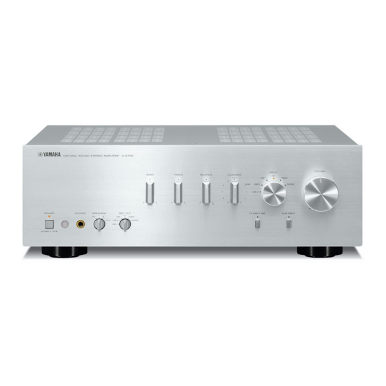
Front Panel ...............................................................3
Rear Panels ...........................................................4–6
Remote Control Panel ..........................................7
Internal View ............................................................9
1 0 1 1 1 7
INTEGRATED AMPLIFIER
A-S700
Failure to follow appropriate service and safety procedures when servicing this product may result in personal injury,
destruction of expensive components, and failure of the product to perform as specifi ed. For these reasons, we advise
all YAMAHA product owners that any service required should be performed by an authorized YAMAHA Retailer or
the appointed service representative.
The presentation or sale of this manual to any individual or fi rm does not constitute authorization, certifi cation or
recognition of any applicable technical capabilities, or establish a principle-agent relationship of any form.
Static discharges can destroy expensive components. Discharge any static electricity your body may have
accumulated by grounding yourself to the ground buss in the unit (heavy gauge black wires connect to this buss).
Turn the unit OFF during disassembly and part replacement. Recheck all work before you apply power to the unit.
.....................................7–8
..... 10
........... 10–16
....................... 17–18
Copyright © 2008
This manual is copyrighted by YAMAHA and may not be copied or
redistributed either in print or electronically without permission.
SERVICE MANUAL
IMPORTANT NOTICE
Ic Data ...................................................................26–28
Block Diagram ........................................................29
Printed Circuit Boards .................................30–43
Pin Connection Diagrams ...................................44
Schematic Diagrams .......................................45–47
Replacement Parts List ................................49–59
Remote Control .....................................................60
All rights reserved.
....................................... 19–25
P.O.Box 1, Hamamatsu, Japan
animate '08.10
Advertisement
Table of Contents

Related Manuals for Yamaha A-S700


Summary of Contents for Yamaha A-S700
-
Page 1: Integrated Amplifier
This manual has been provided for the use of authorized YAMAHA Retailers and their service personnel. It has been assumed that basic service procedures inherent to the industry, and more specifi cally YAMAHA Products, are already known and understood by the users, and have therefore not been restated. -
Page 2: To Service Personnel
A-S700 ■ TO SERVICE PERSONNEL AC LEAKAGE 1. Critical Components Information WALL EQUIPMENT TESTER OR Components having special characteristics are marked OUTLET UNDER TEST EQUIVALENT must be replaced with parts having specifications equal to those originally installed. 2. Leakage Current Measurement (For 120V Models Only) -
Page 3: Impedance Selector
Do not change the setting of the IMPEDANCE SELECTOR switch when the unit power is switched on, as doing so may damage the unit. IMPEDANCE SELECTOR ■ FRONT PANEL A-S700 (U, R, T, K, A, B, G, L, J models) -
Page 4: Rear Panels
A-S700 ■ REAR PANELS A-S700 (U model) A-S700 (R model) A-S700 (T model) - Page 5 A-S700 A-S700 (K model) A-S700 (A model) A-S700 (B model)
- Page 6 A-S700 A-S700 (G model) A-S700 (L model) A-S700 (J model)
-
Page 7: Remote Control Panel
A-S700 ■ REMOTE CONTROL PANEL ■ SPECIFICATIONS / ■ Audio Section / RAS7 Minimum RMS Output Power (Power Amp. Section) / (20 Hz to 20 kHz) 8 ohms, 0.019 % THD ........90 W + 90 W 6 ohms, 0.03 % THD ......... 105 W + 105 W... -
Page 8: Specifications
A-S700 ■ General / Power Supply / Dimensions (W x H x D) / U model ............AC 120 V, 60 Hz ... 435 x 151 x 382 mm (17-1/8" x 5-15/16" x 15-1/16") R model ......AC 110/120/220/230-240 V, 50/60 Hz Weight / T model ............ -
Page 9: Internal View
A-S700 ■ INTERNAL VIEW Top view Power Transformer MAIN (2) P.C.B. MAIN (3) P.C.B. MAIN (8) P.C.B. MAIN (5) P.C.B. (R, L models) MAIN (4) P.C.B. MAIN (7) P.C.B. MAIN (1) P.C.B. MAIN (6) P.C.B. FUNCTION (1) P.C.B. OPERATION (10) P.C.B. -
Page 10: Service Precautions
A-S700 ■ SERVICE PRECAUTIONS / Safety measures • Some internal parts in this product contain high voltages and are dangerous. Be sure to take safety measures during servicing, such as wearing insulating gloves. • Note that positions indicated below are dangerous even after the power is turned off because an electric charge remains and a high voltage continues to exist there. - Page 11 A-S700 Top cover Frame top Knob SP13 Front panel Knob TC Knob SEL unit Lock set screw Knob VOL unit An Allen hex socket screwdriver Fig. 1...
- Page 12 A-S700 • When installing the knob VOL unit: a. Turn the VOLUME (VR805) counterclockwise fully. (Fig. 2) b. Match the slit in the knob VOL unit with the “VOLUME MIN” position and install it in that state. (Fig. 2) At this time, do not tighten the lock set screw.
- Page 13 A-S700 0.5–0.75mm Front panel Lock set screw SW803 VR805 Lock set screw VOLUME MAX. VOLUME MIN. Slit Knob VOL unit Knob SEL unit Fig. 2...
- Page 14 A-S700 3. Removal of Sub-chassis Unit a. Remove 2 screws ( ). (Fig. 3) b. Remove CB283,CB606,CB609,CB611and CB802. (Fig. 3) c. Remove the sub-chassis unit. (Fig. 3) CB283 MAIN (4) P.C.B. CB609 CB606 CB611 Sub-chassis unit CB802 FUNCTION (2) P.C.B.
- Page 15 A-S700 When checking the P.C.B.s: • Put the rubber sheet and cloth over this unit. Then place the P.C.B.s upside down on the cloth and check it. (Fig. 4) • Reconnect all cables (connectors) that have been discon- nected. •...
- Page 16 A-S700 When checking the P.C.B.s: • Spread the rubber sheet and the cloth. Then place this unit on the cloth upside down. (Fig. 5) • Remove 6 screws ( ) and then remove the chassis cover. (Fig. 5) Chassis cover MAIN (1) P.C.B.
- Page 17 A-S700 ■ AMP ADJUSTMENT / ● CONFIRMATION OF IDLING CURRENT 1. Right after power is turned on, confirm that the volt- age across the terminals of R111–R135 (L ch) and R112–R136 (R ch) are between 0.1 mV to 10.0 mV.
- Page 18 A-S700 SCHEMATIC DIAGRAM MAIN (1) R135 L ch 0.1 mV – 10 mV R175 Cut off R111 R112 R176 R ch Cut off 0.1 mV – 10 mV R136...
-
Page 19: Self-Diagnostic Function
A-S700 ■ SELF-DIAGNOSTIC FUNCTION / ● Indication of Protection Information When the power to this unit is turned on and the pow- er indicator is flashing, the normal operation is not available because the protection function is at work. In that case, the protection information can be indi- cated by following procedures. - Page 20 A-S700 • List of protection information The protection information is indicated by the flashing pattern of the POWER indicator. (Fig. 2) Types of protection function / POWER indicator flashing pattern / : Lit / : Off / PS protection /...
- Page 21 A-S700 c. I protection L/Rch Cause: Excess current flow into ampli- fier. Speaker terminal shorted. (*) Normal value: LOW (0V) Detection port: PRI (80 pin of microprocessor IC602 of FUNCTION P.C.B.) Detected at: PRI (Amplifier output L/Rch of MAIN P.C.B.)
- Page 22 A-S700 ● Starting in the Protection Cancel mode If the protection function works and causes hindrance to trouble shoot, cancel the protection function as described below, and it will be possible to turn on the power. • Operation procedures Perform this operation procedure within 30 seconds after turning off the power.
- Page 23 A-S700 Note) • Applying the power to this unit without correcting the abnormality can be dangerous and cause additional circuit damage. To avoid this, if protection function has been activat- ed the number of times which is set beforehand, the power will not turn on even when the “POWER”...
-
Page 24: Indication Of Firmware Version
A-S700 ● Indication of Firmware Version The firmware version of the microprocessor is indicat- ed in the binary code (BCD) using INPUT indicates. • Operation procedures Perform this operation procedure within 30 seconds after turning off the power. 1. Press “POWER”, “CD DIRECT AMP”, and “PURE DIRECT”... -
Page 25: Factory Reset
A-S700 ● Factory Reset Return below settings to those when shipped from the factory. In the parentheses ( ) are settings when shipped from the factory. a. Power (OFF) b. INPUT (CD) c. Protection history (None) d. Number of times when protection is detected (0) e. -
Page 26: Ic Data
A-S700 ■ IC DATA IC602: M30302MAP-A95FP (FUNCTION P.C.B.) Single-chip 16-bit CMOS microprocessor Port P0 Port P1 Port P2 Port P3 Port P4 Port P5 Port P6 Internal peripheral function System clock A/D converter generation circuit Timer (16-bit) (10-bits 18-channels Output (timer A): 3... - Page 27 A-S700 Port Name Function Name Detail of Function P96/ANEX1 P95/ANEX0 DEST1 P92/TB2in DEST0 P91/TB1in MOD1 P90/TB0in MOD0 BYTE BYTE MCU Vss: when single chip mode is used (Gnd) Vss: when single chip mode is used CNVss CNVss (Pull down) Vcc: when flash writing is used...
- Page 28 A-S700 Port Name Function Name Detail of Function 56 P36 LED_TU Input indicators (TUNER) 57 P35 LED_CD Input indicators (CD) 58 P34 LED_LN1 Input indicators (LINE1) 59 P33 LED_LN2 Input indicators (LINE2) 60 P32 LED_LN3 Input indicators (LINE3) 61 P31...
- Page 29 A-S700 ■ BLOCK DIAGRAM CD DIRECT AMP SW801 CD DIRECT IN RY103 R177,178 JK801 OPERATION MUTING POWER 19,22,25 • See page 46 → Q804,805 C871,872 8,9,12 PHONES SCHEMATIC DIAGRAM HP RELAY MUTE CONTROL CD DIRECT ON RY101 C119,120 PDOUT SPEAKER A...
-
Page 30: Printed Circuit Boards
A-S700 ■ PRINTED CIRCUIT BOARDS FUNCTION (1) P.C.B. FUNCTION (1) P.C.B. (Side A) (Side A) FUNCTION (2) FUNCTION (2) (CB603) (CB602) CB501 CB502 • Semiconductor Location Ref no. Location Q505 Q506... - Page 31 A-S700 FUNCTION (1) P.C.B. (Side B) IC508 IC502 IC501 IC507 IC506 IC505 • Semiconductor Location Ref no. Location D503 D504 IC501 IC502 IC505 IC506 IC507 IC508...
- Page 32 A-S700 FUNCTION (2) P.C.B. (Side A) OPERATION (1) OPERATION (10) (CB802) (CB816) W601 OPERATION (1) OPERATION (1) (CB801) CB607 (CB803) VRdn VRup CLED PLED CDon RM1+ PDon RM1- MTMI RM2+ RM2- DTFD CKFD CEFD KEY1 KEY0 N.C. /BLK SPSW MPSW...
- Page 33 A-S700 FUNCTION (2) P.C.B. (Side B) POINT A XL601 (Pin 13 of IC602) • Semiconductor Location Ref no. Location D601 D602 D603 D604 D605 D606 D607 IC602 Q601 Q602 Q606...
- Page 34 A-S700 OPERATION (1) P.C.B. (Side A) PURE DIRECT CD DIRECT AMP SP_LED MAIN (1) (CB103) SPAB SPSW CB803 OPERATION (5) (W806) OPERATION (9) (CB809) TIL+ TIL- OPERATION (11) VRup TIR- (CB805) VRdn TIR+ FUNCTION (2) (CB606) +15TC CB807 CB802 CB801...
- Page 35 A-S700 OPERATION (1) P.C.B. (Side B) IC801 IC802 • Semiconductor Location Ref no. Location IC801 IC802 Q801 Q802 Q803 Q804 Q805...
- Page 36 A-S700 OPERATION (2) P.C.B. OPERATION (3) P.C.B. OPERATION (4) P.C.B. (Side A) (Side A) (Side A) VOLUME LOUDNESS INPUT indicators LED_AUX LED_MD LED_TAPE LINE1 LED_CD LED_TU LED_PHO LINE2 TUNER FUNCTION (2) PHONO (CB609) LINE3 BALL TREL INPUT TRER BALR VRup...
- Page 37 A-S700 OPERATION (2) P.C.B. OPERATION (3) P.C.B. OPERATION (4) P.C.B. (Side B) (Side B) (Side B) • Semiconductor Location Ref no. Location D808 Q806 Q807 Q808 Q809 Q810 Q811 Q812 Q813...
- Page 38 A-S700 OPERATION (5) P.C.B. OPERATION (6) P.C.B. OPERATION (7) P.C.B. (Side A) (Side A) (Side A) POWER ON/STANDBY OPERATION (1) (CB808) CB813 W806 W808 CB814 SPSW POWER indicator REC OUT SPEAKERS OPERATION (8) P.C.B. (Side A) OPERATION (9) P.C.B. (Side A)
- Page 39 A-S700 OPERATION (5) P.C.B. OPERATION (6) P.C.B. OPERATION (7) P.C.B. (Side B) (Side B) (Side B) OPERATION (8) P.C.B. (Side B) OPERATION (9) P.C.B. (Side B) • Semiconductor Location Ref no. Location D811 D812 Q814...
- Page 40 A-S700 OPERATION (10) P.C.B. (Side A) FUNCTION (2) (CB607) CB816 BASS TREBLE BALANCE OPERATION (11) P.C.B. (Side A) BALL TREL TIL+ TIL- OPERATION (1) TRER (W814) TIR- BALR TIR+ +15TC -15TC OPERATION (2) (W805A)
- Page 41 A-S700 OPERATION (10) P.C.B. (Side B) IC804 IC805 OPERATION (11) P.C.B. (Side B) • Semiconductor Location Ref no. Location IC803 IC804 IC805 Q815 IC803 Q816...
- Page 42 A-S700 Safety measures • Some internal parts in this product contain high voltages and are dangerous. Be sure to take safety measures during servicing, such as wearing insulating gloves. • Note that positions indicated below are dangerous even after the power is turned off be- MAIN (1) P.C.B.
- Page 43 A-S700 MAIN (2) P.C.B. MAIN (3) P.C.B. MAIN (5) P.C.B. (Side A) (Side A) (Side A) (Side A) (Side A) (Side A) R, L models POWER TRANSFORMER POWER TRANSFORMER MAIN (5) (W291A)(W291B) R model CB294 CB293 W291B L model CB256...
-
Page 44: Pin Connection Diagrams
A-S700 ■ PIN CONNECTION DIAGRAMS • ICs • Transistors BD3841FS LB1641 LM61CIZ M30302MAP-A95FP 2N5401C-AT 2N5551C-AT 2SA970 2SA1037K 2SK3850 2SA1145 2SD1938F 2SC2705 2SA1015-Y (TPE2,F) NJM2068MD-TE2 NJU7313AM OP275GSR S-812C55AY-T-G TC4013BP 2SA1694 O,P,Y 2SA1358 O,Y 2SA1708 2SC1815 2SC3421 O,Y 2SC4467 O,P,Y 2SD1915F DTC144EKA... -
Page 45: Schematic Diagrams
A-S700 SCHEMATIC DIAGRAMS FUNCTION Page 47 Page 46 Page 46 to MAIN (1)_CB284 to OPERATION (1)_CB803 to OPERATION (10)_CB816 TUNER IN CD IN 13.5 IC505 POINT A XL601 (Pin 13 of IC602) CB611 IC505 IC601 -13.3 13.5 IC506 IC501 IC501... - Page 46 A-S700 OPERATION CD DIRECT AMP W801 OPERATION (11) OPERATION (2) Page 47 to MAIN (1)_CB103 PD IN -14.7 TONE IN CB801 VOL OUT 14.7 IC803 (CD DIRECT) -14.7 OUT L VOL IN W805A W805B TONE OUT W802 CB804 CD IN...
- Page 47 A-S700 MAIN Page 46 Page 45 to OPERATION (8)_W811 to FUNCTION (2)_CB605 To POWER TRANSFORMER MAIN (4) WJ36180 WJ36180 WJ36180 WJ36180 WJ36180 WJ36180 WJ36180 IMPEDANCE SELECTOR MAIN (6) HIGH/LOW CB101 W101 IC101 CB106 WE10290 WJ61060 WE10290 WE10290 WE10290 WE10290 WE10290...
-
Page 48: Replacement Parts List
A-S700 ■ REPLACEMENT PARTS LIST • ELECTRICAL COMPONENT PARTS WARNING ● Components having special characteristics are marked and must be replaced with parts having specifications equal to those originally installed. ● The chip resistor is not supplied as a replacement part. - Page 49 A-S700 P.C.B. FUNCTION Ref No. Part No. Description Remarks Markets WQ040000 P.C.B. FUNCTION PCB FUNCTION CB501 V7828400 SOCKET 17P SE TUC SERIES コネクターソケット CB502 V7827900 SOCKET 12P TE TUC SERIES コネクターソケット CB602 V7826200 CN 12P TE TUC SERIES コネクタープラグ CB603 V7826700 CN 17P TE TUC SERIES コネクタープラグ...
- Page 50 A-S700 P.C.B. FUNCTION and P.C.B. OPERATION Ref No. Part No. Description Remarks Markets R569-570 V8070900 R.MTL.FLM 100 Ω 金属被膜抵抗 ST601 V4040500 SCR.TERM スクリュー/ターミナル XL601 WA674700 RSNR.CE 16MHz CSTLS16M0X51 セラミック振動子 WQ040300 P.C.B. OPERATION PCB OPERATION CB801 VP682200 CN.BS.PIN FFCコネクター CB802 VB858800 CN.BS.PIN ベースピン...
- Page 51 A-S700 P.C.B. OPERATION and P.C.B. MAIN Ref No. Part No. Description Remarks Markets C871-872 WJ605000 C.MYLAR 0.01uF 50V J マイラーコン C873-874 UR238100 C.EL 100uF ケミコン C875-876 UU337100 C.EL 10uF ケミコン RA3 C877 WJ605000 C.MYLAR 0.01uF 50V J マイラーコン C878-881 VR168400 C.MYLAR 0.12uF...
- Page 52 A-S700 P.C.B. MAIN Ref No. Part No. Description Remarks Markets CB106 LB932070 CN.BS.PIN ベースポスト CB128 V7826600 CN 16P TE TUC SERIES コネクタープラグ CB252 VG879900 CN.BS.PIN ベースピン CB253-254 WN103000 CLIP.FUSE TP00351-31 ヒューズクリップ CB255-256 WN103000 CLIP.FUSE TP00351-31 ヒューズクリップ CB257 VG879900 CN.BS.PIN ベースピン...
- Page 53 A-S700 P.C.B. MAIN Ref No. Part No. Description Remarks Markets C274 WJ603700 C.MYLAR 1000pF マイラーコン C275 WJ605000 C.MYLAR 0.01uF 50V J マイラーコン D101-106 VD631600 DIODE 1SS133,176 ダイオード D107-108 VN008700 DIODE 1SS270A ダイオード D109 VD631600 DIODE 1SS133,176 ダイオード D111-112 VD631600 DIODE 1SS133,176 ダイオード...
- Page 54 A-S700 P.C.B. MAIN Carbon Resistors Value 1/4W Type Part No. 1/6W Type Part No. Value 1/4W Type Part No. 1/6W Type Part No. Ref No. Part No. Description Remarks Markets 1.0 Ω HJ35 3100 HF85 3100 11 kΩ HF45 7110...
- Page 55 A-S700 • OVERALL ASS'Y K model R model 129 129 R model AMP UNIT (10) 112-1 111-1 FRONT PANEL UNIT R, L models 200-1...
-
Page 56: Remote Control
A-S700 Ref No. Part No. Description Remarks Markets Ref No. Part No. Description Remarks Markets WQ040000 P.C.B. ASS'Y FUNCTION PCB FUNCTION V5247600 DAMPER ダンパー WQ039100 P.C.B. ASS'Y MAIN PCB MAIN WP084000 CAP POWER POWER ON/OFF キャップパワー WQ039200 P.C.B. ASS'Y MAIN PCB MAIN WP083900 CAP POWER POWER ON/OFF キャップパワー... - Page 57 A-S700 • FRONT PANEL and SUB PANEL UNIT Ref No. Part No. Description Remarks Markets 2-120 WP080500 FRONT PANEL フロントパネル WP080400 FRONT PANEL フロントパネル WP080800 SUPPORT LENS A サポートレンズA WP081200 SIDE PLATE サイドプレート WP081100 SIDE PLATE サイドプレート WK863700 LENS RC PURPLE レンズRC...
- Page 58 A-S700 • AMP UNIT Ref No. Part No. Description Remarks Markets 3-43 3-1-1A iX615750 TRANSISTOR 2SA1694 O,P,Y Q121A, Q123A トランジスタ 3-1-1C iX615760 TRANSISTOR 2SC4467 O,P,Y Q121C, Q123C トランジスタ 3-1-6 3-1-5 VV849300 RADIATION SHEET 19x24 放熱シート 3-43 3-2-1C 3-1-6 VP922500 DAMPER 2x10x170 ダンパー...
- Page 59 A-S700 ■ REMOTE CONTROL SCHEMATIC DIAGRAM PANEL KEY NO. LAYOUT KEY CODE Customer Code Data Code Function 7986 6F90 7986 01FE 3.3 ohms 7986 54AB PHONO IR-LED 47uF/10V 0.1uF U1 SC73P1601 7986 TUNER 7986 0AF5 7986 11EE LINE1 220 ohms...
- Page 60 A-S700 MEMO...
- Page 61 A-S700...