Table of Contents
Advertisement
Installationshinweise
Rauchansaugsystem
⋅
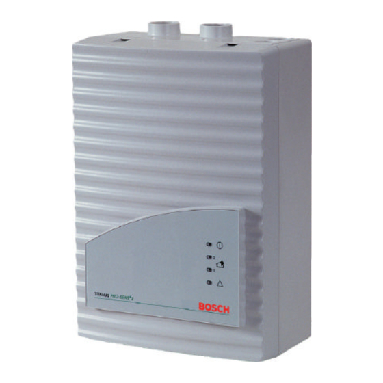
TITANUS PRO
SENS
⋅
TITANUS PRO
SENS
1
Betriebs-LED
2
Alarm-LED für Detektormodul 2
Alarm-LED für Detektormodul 1
3
LED Sammelstörung
4
Vorgestanzte Kabeleinführungen zum
5
Anschluss an BMZ oder Stromversor-
gung (Ein-/Ausgang)
Anschluss Rohrsystem 1
6
Anschluss Rohrsystem 2
7
Anschluss für Luftrückführung
8
Bosch Sicherheitssysteme GmbH
Installation Instructions
Aspirating Smoke Detector
®
TITANUS PRO
TP-1 A
®
TITANUS PRO
TP-2 A
1
Operation LED
2
Alarm LED for detector module 2
Alarm LED for detector module 1
3
Collective fault LED
4
Pre-punched cable entries for connec-
5
tion to fire panel or power supply (in-
put/output)
Connection pipe system 1
6
Connection pipe system 2
7
Connection for air-return pipe
8
®
⋅
SENS
TP-1 A
⋅
®
SENS
TP-2 A
- 1 -
Instructions de mise en place
Système aspirant de
détection d'incendie
⋅
TITANUS PRO
SENS
⋅
TITANUS PRO
SENS
1
LED « en service »
2
LED d'alarme pour cellule de détection 2
LED d'alarme pour cellule de détection 1
3
LED de dérangement collectif
4
Entrées de câbles prédécoupées pour la
5
connexion au tableau de signalisation
ou à l'alimentation (entrée/sortie)
Raccordement canalisation 1
6
Raccordement canalisation 2
7
Connexion pour retour d'air
8
F.01U.045.264 | de/en/fr | A6 | 2007.03
®
TP-1 A
®
TP-2 A
Advertisement
Table of Contents

Related Manuals for Bosch Titanus Pro?Sens TP-1 A


Summary of Contents for Bosch Titanus Pro?Sens TP-1 A
- Page 1 Connection pipe system 1 Raccordement canalisation 1 Anschluss Rohrsystem 2 Connection pipe system 2 Raccordement canalisation 2 Anschluss für Luftrückführung Connection for air-return pipe Connexion pour retour d’air Bosch Sicherheitssysteme GmbH - 1 - F.01U.045.264 | de/en/fr | A6 | 2007.03...
-
Page 2: Installation Of The Detector Module
TP-2 A avec deux cellules de détections, sui- ® TP-2 A folgen Sie den weiteren ing. vez les instructions ci-dessous. PRO·SENS Anweisungen. Bosch Sicherheitssysteme GmbH - 2 - F.01U.045.264 | de/en/fr | A6 | 2007.03... - Page 3 9. Schließen Sie die Anzeigeplatine wieder an connecteurs sur la carte principale. die Grundplatine an. Achten Sie hierbei e- benfalls auf die Anschlüsse und Beschriftun- gen der Grundplatine. Bosch Sicherheitssysteme GmbH - 3 - F.01U.045.264 | de/en/fr | A6 | 2007.03...
- Page 4 ⋅ ⋅ ⋅ Einstellung LOGIC SENS Setting LOGIC SENS Réglage LOGIC SENS S1.10 S1.10 S1.10 ⋅ sans LOGIC SENS ⋅ avec LOGIC SENS Bosch Sicherheitssysteme GmbH - 4 - F.01U.045.264 | de/en/fr | A6 | 2007.03...
- Page 5 Setting the fan voltage Réglage de la tension du ventilateur Jumper JU1, Jumper JU1, cavalier JU1, Pin-Nr. Pin no. n° broche 6,9 V 6.9 V 6,9 V Bosch Sicherheitssysteme GmbH - 5 - F.01U.045.264 | de/en/fr | A6 | 2007.03...
- Page 6 Plaque de fixation type MT-1 horizontale Montage horizontal installation montage horizontal Halterung Typ MT-1 Support type MT-1 Plaque de fixation type MT-1 vertikale Montage vertical installation montage vertical Bosch Sicherheitssysteme GmbH - 6 - F.01U.045.264 | de/en/fr | A6 | 2007.03...
-
Page 7: Installation Des Gerätes
) durch die vorbereiteten M20- oder M25-Anbaustutzen Gerät schneiden Sie diese anschließend innerhalb des Gerätes auf die benötigte Länge ab. 6. Verkabeln Sie das Gerät nach der im fol- genden beschriebenen Aufschaltung. Bosch Sicherheitssysteme GmbH - 7 - F.01U.045.264 | de/en/fr | A6 | 2007.03... - Page 8 DM = Detektormodul detector module cellule de détection rouge bk = schwarz black noir gelb yellow jaune weiß white blanc DC/DC CONVERTER= GAT 100 DC/DC Converter DC/DC Converter Bosch Sicherheitssysteme GmbH - 8 - F.01U.045.264 | de/en/fr | A6 | 2007.03...
- Page 9 électrique externe est néces- saire! ➂ ➂ ➂ Schirmbeidrähte Klemmen Connect the screening wires to terminals Connectez les fils blindés aux bornes III1/III2 anschließen. III1/III2. III1/III2. Bosch Sicherheitssysteme GmbH - 9 - F.01U.045.264 | de/en/fr | A6 | 2007.03...
- Page 10 Schalter S1 und S2 am NBK 100 LSN sind Switches S1 and S2 on the NBK 100 LSN Commutateurs S1 et S2 à NBK 100 LSN offen. are open. sont ouverts. Bosch Sicherheitssysteme GmbH - 10 - F.01U.045.264 | de/en/fr | A6 | 2007.03...
- Page 11 FPA-5000, une dépendance à deux détecteurs melderabhängigkeit als auch eine Zweigruppen- zone dependency can be realized. et une dépendance à deux zones sont possi- abhängigkeit realisiert werden. bles. Bosch Sicherheitssysteme GmbH - 11 - F.01U.045.264 | de/en/fr | A6 | 2007.03...
-
Page 12: Initial Setup
Anderenfalls muss die Initialisierung erneut durchgeführt werden. BOSCH Sicherheitssysteme GmbH Robert-Koch-Str. 100 D- 85221 Ottobrunn Telefon: ++ 49 089 6290-0 Telefax: ++ 49 089 6290-1039 E-Mail: info.service@de.bosch.com www.bosch-sicherheitssysteme.de www.boschsecuritysystems.com Bosch Sicherheitssysteme GmbH - 12 - F.01U.045.264 | de/en/fr | A6 | 2007.03...