Table of Contents
Advertisement
Quick Links
Download this manual
See also:
Instruction Manual
Advertisement
Chapters
Table of Contents

Related Manuals for Sony KP-48PS2


Summary of Contents for Sony KP-48PS2
-
Page 1: Service Manual
SERVICE MANUAL RE-3 CHASSIS MODEL COMMANDER DEST. CHASSIS NO. KP-48PS2 RM-903 SCC-P38G-A KP-61PS2 RM-903 SCC-P38H-A RM-903 KP-48PS2 KP-61PS2 PROJECTION TV... - Page 2 VIEWS AND IN THE PARTS LIST ARE CRITICAL TO REMOVING THE ANODE. SAFE OPERATION. REPLACE THESE COMPONENTS WITH SONY PARTS WHOSE PART NUMBERS AP- PEAR AS SHOWN IN THIS MANUAL OR IN SUPPLE- MENTS PUBLISHED BY SONY. – 2 –...
-
Page 3: Table Of Contents
KP-48PS2/61PS2 RM-903 TABLE OF CONTENTS Section Title Page Section Title Page 1. SELF DIAGNOSIS FUNCTION 5-2-3. Operation Method for 1-1. RE-3 Serf Diagnostic Software ......Projector Engine Mode ........1-2. Error Detection Monitor ........5-2-4. Projector Engine Adjustment 1-2-1. Error Monitor Menu ........ - Page 4 KP-48PS2/61PS2 RM-903 Section Title Page (24) Schematic Diagram of J (1/5) Board ....(25) Schematic Diagram of J (2/5) Board ....(26) Schematic Diagram of J (3/5) Board ....(27) Schematic Diagram of J (4/5) Board ....(28) Schematic Diagram of J (5/5) Board ....
-
Page 5: Self Diagnosis Function
KP-48PS2/61PS2 SECTION 1 RM-903 SELF DIAGNOSIS FUNCTION 1-1. RE-3 SELF DIAGNOSTIC SOFTWARE The identification of errors within the RE-3 chassis is triggered in one of two ways : - 1: Busy or 2: Device failure to respond to IIC. In the event of one of these situations arising the software will first try to release the bus if busy (Failure to do so will report with continuous flashing LED) and then communicate with each device in turn to establish if a device is faulty. -
Page 6: Error Detection Monitor
KP-48PS2/61PS2 RM-903 1-2. ERROR DETECTION MONITOR Device acknowledge is used to check IIC errors. Device acknowledge is checked by sending an IIC start sequence during CRT power on. Each device is checked three times, if there is no acknowledge after every attempt, it will be regarded as an error. -
Page 7: Error Reader Display
KP-48PS2/61PS2 RM-903 1-2-2. Error Reader Display The error reader display is connected to the service connector to read actual error codes. The part number for the error reader display is S-188-900-10. Once an error has been detected it will then be displayed on the two digit error reader. The errors displayed refer to the following table:... -
Page 8: Disassembly
KP-48PS2/61PS2 SECTION 2 RM-903 DISASSEMBLY 2-1. REAR BOARD REMOVAL 2-2. MAIN BRACKET BLOCK REMOVAL • KP-48 1 Light shield board 2 Rear board 2 Two screws (Hexagon Head) 3 Main bracket block 1 Thirteen screws (Hexagon head) • KP-61 2-3. SERVICE POSITION... -
Page 9: Control Panel Block And Resistor Assembly (Focus Pack) Removal
KP-48PS2/61PS2 RM-903 2-4. CONTROL PANEL BLOCK AND 2-6. CHASSIS BLOCK REMOVAL RESISTOR ASSEMBLY (1) MAIN BRACKET REMOVAL (FOCUS PACK) REMOVAL 5 Control panel block 4 Two screws (Hexagon head) Two screws (Hexagon head) 3 Front board Set the main 2 Nine screws... -
Page 10: Terminal Board Removal
KP-48PS2/61PS2 RM-903 2-7. TERMINAL BOARD REMOVAL 3 RF cable 4 Terminal board 2 Two screws (+BVTP 3 x 12) 1 Five screws (+BVTP 4 x 16) 2-8. BD, DS, D BOARDS REMOVAL 2 Printed circuit 1 Screw board support (+BVTP 3 x 12) -
Page 11: G Board Removal
KP-48PS2/61PS2 RM-903 2-9. G BOARD REMOVAL 1 Five claws 2 G board 2-10. J, B3, E, M, S BOARDS REMOVAL 9 E board 4 Four screws 8 Claw (+BVTT 3 x 8) !- M board 5 Shied case 0 Claw... -
Page 12: A Board Removal
KP-48PS2/61PS2 RM-903 2-11. A BOARD REMOVAL 1 Screw (+BVTP 3 x 12) 3 A board 2 Two claws 2-12. HIGH-VOLTAGE 2-13. PICTURE TUBE REMOVAL CABLE REMOVAL AND INSTALLATION (1) Removal Removing the arrow-marked screw is strictly inhibited. If removed, it may cause liquid spill... -
Page 13: Set-Up Adjustments
KP-48PS2/61PS2 SECTION 3 RM-903 SET-UP ADJUSTMENTS 3-1. SCREEN VOLTAGE ADJUSTMENT 5. Rotate the green lens and align to obtain the best lens focus at the center area. (ROUGH ALIGNMENT) 6. Rotate the green focus VR on the focus pack and align to 1. -
Page 14: 2-Pole Magnet Adjustment
KP-48PS2/61PS2 RM-903 3-5. 2-POLE MAGNET ADJUSTMENT 3-7. GREEN, RED AND BLUE FOCUS 1. Receive the Dot signal. ADJUSTMENT 2. Place the caps on the red and blue lens so that only the green 3-7-1. Green, Red and Blue Lens Focus Adjustment color is shown. -
Page 15: Safety Related Adjustment
KP-48PS2/61PS2 SECTION 4 RM-903 SAFETY RELATED ADJUSTMENT When replacing the following components marked with ] on D BOARD – CONDUCTOR SIDE – the schematic diagram, always check hold-down voltage and CN5003 if necessary re-adjust. Part Replaced ([) CN5002 R9901 Part Replaced (]) -
Page 16: Electrical Adjustments
KP-48PS2/61PS2 SECTION 5 RM-903 ELECTRICAL ADJUSTMENTS 5-1. ADJUSTMENTS WITH COMMANDER 3. Selection of Screen Format The 16 : 9 mode is selected only when the DRC100 (PAL) mode Service adjustment to this model can performed with the sup- is active. -
Page 17: Screen Display For Service Menu
KP-48PS2/61PS2 RM-903 • Initialising b Basic Setting 5-1-4. Screen Display for Service Menu If each item of service menu is selected, the following screen is Basic Setting displayed. Descr. Data • Initialising Sys. B/G Sys. D/K Sys. L Initialising Sys. I (UK) Sys. - Page 18 KP-48PS2/61PS2 RM-903 • Device Register Setting b Deflection • Monitoring Note: Prior to starting Main Deflection Adjustment, the value Monitoring displayed here (shaded portion) must be set to the Deflec- tion data. Device Status Monitor Error Monitor Deflection Production Monitor NVM Monitor No Descr.
- Page 19 KP-48PS2/61PS2 RM-903 • Device Register Setting b Dynamic Convergence • Device Register Setting b Colour Decoder 2 Dynamic Convergence Colour Decoder 2 No Descr. Def. Data No Descr. Def. Data Range TINT H stat SUB COLOUR H amp l SUB CONTR...
- Page 20 KP-48PS2/61PS2 RM-903 • Device Register Setting b External PLL MID-X • Device Register Setting b Picture Booster External PLL MID-X Picture Booster No Descr. Def. Data No Descr. Def. Data VCO7-0PAL VCO7-0NTSC VCO11-8 Select : v V Last menu : b...
-
Page 21: Service List (Projector Engine)
KP-48PS2/61PS2 RM-903 5-1-5. Service List (Projector Engine) : Fixed data Note : Prior to starting Main Deflection Adjustment, the data (GRN, BLU, RED) must be set to the standard values of DRC100 (PAL) mode. Standard Data Item Adjustment Data Name/Description... -
Page 22: Registration Adjustment
KP-48PS2/61PS2 RM-903 5-2. REGISTRATION ADJUSTMENT 5. Adjust “1 V-Size” and “6 H-Size” so that the picture size is 5-2-1. Data Setting Before Adjustment within the specification. SPEC Overscan Spec. = 7.5% Note: Prior to starting Registration Adjustment, the data must be set by the following method. - Page 23 KP-48PS2/61PS2 RM-903 5-2-3. Operation Method for Projector Engine Commander Function Mode Buttons Mode Description WRITE Writes data to NVM. MUTE TV STANDBY 7 + - READ Reads data from NVM. VIDEO 5 + - INIT Service data initialization. Not stored.
-
Page 24: Operation Method For Projector Engine Mode
KP-48PS2/61PS2 RM-903 3. Operation Method for Fine Adjustment 5-2-4. Projector Engine Adjustment (in GRN, BLU, or RED Mode) (Sub Deflection Adjustment) Note: Prior to starting this adjustment, make sure that the data of 1) Select the Projector Engine mode. GRN, BLU, and RED items in the DRC100 (PAL) mode 2) Select FDIS so that the data at each position can be displayed are same as those data given in “5-1-5. - Page 25 KP-48PS2/61PS2 RM-903 2. Blue Adjustment • BLU SIZE (horizontally/vertically) 1) Place a cap on the red lens so that green and blue colors are Adjust so that each distance from center to left end and to right displayed. end is equal.
- Page 26 KP-48PS2/61PS2 RM-903 3. Red Adjustment <Copy of Registration Data from PAL to NTSC> 1) Place a cap on the blue lens so that green and red colors are 1. Make sure that the adjustment for DRC50 (PAL) mode fin- displayed.
-
Page 27: Auto Convergence Offset
KP-48PS2/61PS2 RM-903 5-3. AUTO CONVERGENCE OFFSET 5-5. WHITE BALANCE ADJUSTMENT 1. Enter the monoscope signal. This adjustment must be performed after the registration adjust- 2. Press “MENU” button on the commander to enter the Picture ment was made or after readjustment was made by any reason. -
Page 28: Sub Color Adjustment
KP-48PS2/61PS2 RM-903 5-7. SUB COLOR ADJUSTMENT 5-8. SUB COLOR OFFSET (61 inch model only) 1. Confirm the result performed in 5-7. SUB COLOR AD- 1. Enter the color bar signal. JUSTMENT. 2. Connect the oscilloscope probe to the CN4500 pin 5 on the E board. -
Page 29: Test-Test Mode
KP-48PS2/61PS2 RM-903 5-9. TEST-TEST MODE Is available by pressing “OSD”, “5”, “Volume minus”, “TV” button in the standby mode, OSD “TT--” appears. The functions de- scribed below are available by pressing the two numbers. To release the Test-Test mode, Press “-” twice or switch the TV set into standby mode. -
Page 30: Diagrams
KP-48PS2/61PS2 SECTION 6 RM-903 DIAGRAMS 6-1. BLOCK DIAGRAM (1) (AV SELECT SW,VIDEO PROCESS) IC8601 IC8301 PICTURE BOOSTER MAIN COLOR DECODER CN8101 CN8900 Q8620,8621,8623 Q8604,8609 V MAIN IN Cr OUT -VIN -V OUT BLUE IN AMP,BUFF AMP,BUFF GREEN IN RED IN... -
Page 31: Block Diagram
KP-48PS2/61PS2 RM-903 BLOCK DIAGRAM (2) BLOCK DIAGRAM(7) BLOCK DIAGRAM(6) BLOCK DIAGRAM(9) BLOCK DIAGRAM(9) BLOCK DIAGRAM(3) BLOCK DIAGRAM(6) M BOARD CN9001 D BOARD CN5016 G BOARD CN6303 H1 BOARD CN3102 B3 BOARD CN502 D BOARD CN5017 FOR CHECK CN1504 CN1502 CN1201... -
Page 32: Block Diagram
KP-48PS2/61PS2 RM-903 BLOCK DIAGRAM (3) IC801 MID-X IC601 IC901 D/A CONVERTER IC501 MAIN A/D CONVERTER DYO2 CRCYIN0 DSPY0 CN502(2/2) CN502(1/2) DY0-7 G0-7 Q901,908 Q501,521 63 VIN(A) D(A)1 DIY0 Y 100 OUT Y MAIN IN DYO9 CRCYIN7 DSPY7 BUFF BUFF Y0-7... -
Page 33: Block Diagram
KP-48PS2/61PS2 RM-903 BLOCK DIAGRAM (4) (PJED,REGI CORRECTION) IC2617 RESET TO IC2621, 4 RST D+5V IC2619 IC2619 IC2627(1/4) PJED-CPU IC2626(1/4) 1V CONV, CN2603 PEAK HOLD Q2611 IC2607(1/3) CN2602(2/2) UPPER UPPER 18 I AREGI D0 OSD MIX Q2602 SENSOR RE-R BUFF IC2627(2/4) -
Page 34: Block Diagram
KP-48PS2/61PS2 BLOCK DIAGRAM (5) RM-903 V901 V902 V903 PICTURE TUBE PICTURE TUBE PICTURE TUBE TO BLOCK DIAGRAM(6) TO BLOCK DIAGRAM(6) TO BLOCK DIAGRAM(6) HV BLOCK HV BLOCK HV BLOCK (R/G/B/VM OUT,YCJ) (R CRT DRIVE) (G CRT DRIVE) (B CRT DRIVE) -
Page 35: Block Diagram
KP-48PS2/61PS2 RM-903 BLOCK DIAGRAM (6) TO BLOCK DIAGRAM(4) TO BLOCK DIAGRAM(5) TO BLOCK DIAGRAM(5) TO BLOCK DIAGRAM(5) BD BOARD CN2602 ZB BOARD CN7802 ZG BOARD CN7603 ZR BOARD CN7404 CN5015 CN5012 CN5011 CN5011 CN5401 Q5503-5506 Q5501,5502 CN5402(2/2) REGI MUTE IC5502(2/3) -
Page 36: Block Diagram
KP-48PS2/61PS2 RM-903 BLOCK DIAGRAM (7) (MICRO CONTROL,TEXT) I9112 RGB-SW CN9001(1/2) CN9001(2/2) Q9105 2 X0 RE-R TXTR BUFF RE-G 12 Z0 RE-B 5 Y0 RE-YS Q9106 TXTG BUFF 1 X1 13 Z1 Q9104 3 Y1 TXTB BUFF Q9502 IC9502 10 CVBS... -
Page 37: Block Diagram
KP-48PS2/61PS2 RM-903 BLOCK DIAGRAM (8) (AUDIO PROCESS) IC4702 SOUND PROCESSOR CN4701(1/2) CN4701(2/2) TV OUT L MAIN L IN A1 56 AV MAIN L IN L-TV TV OUT R MAIN R IN A2 AV MAIN R IN R-TV Q4703 BIAS Q4701... -
Page 38: Block Diagram
KP-48PS2/61PS2 RM-903 BLOCK DIAGRAM (9) T6004 PIT AUDIO (POWER SUPPLY) (USER CONTROL,MAIN SW) HP OUT, PROGR + IC3101 PROGR - USER CONTROL D6302 IR RECEIVER S3101 S3102 S3103 CN3102 CN6301 RECT CN3202 J3201 +17V SIRCS HP R OUT HEAD HP L OUT... -
Page 39: Frame Schematic Diagram
KP-48PS2/61PS2 6-2. FRAME SCHEMATIC DIAGRAM RM-903 CN1404 CN1901 :B TO B AUDIO OUT,AUDIO PROTECT, TUNER CN1102 :S-MICRO CRT BRACKET(C) SP OUT L AUDIO GND SP OUT R AUDIO GND CN1201 :B TO B TO CRT(R) TO CRT(G) TO CRT(B) CN4701... -
Page 40: Circuit Boards Location
KP-48PS2/61PS2 RM-903 • Divided schematic diagram 6-3. CIRCUIT BOARDS LOCATION 6-4. SCHEMATIC DIAGRAMS AND Terminal name of semiconductors in silk screen Schematic diagrams of A, BD, D, G, J and M boards are divided PRINTED WIRING BOARDS printed circuit ( into several pieces. -
Page 41: Schematic Diagram Of A (1/3) Board
KP-48PS2/61PS2 (1) Schematic Diagram of A (1/3) Board RM-903 Q1101 2SC2412K D1101 D1102 Q1102 PROT 1SS355 1SS355 2SA1037AK D1410 D1411 D1103 Q1201 MA3220M-TX MA3220M-TX PROT R1211 1SS355 2SC2412K 4.7k D1104 Q1202 MUTE :CHIP Q1204 +5V STBY 1SS355 2SC2412K 11.8 2SC2412K... -
Page 42: Schematic Diagram Of A (2/3) Board
KP-48PS2/61PS2 (2) Schematic Diagram of A (2/3) Board RM-903 (2/3) (CONNECTOR) C1405 R1416 2.2k L1401 6.8µH Q1402 :CHIP :CHIP 2SA1037K VO(1) BUFF R1418 C1427 33pF :CHIP R1417 CH:CHIP MEV(1) TO A2/3,A3/3_10 :CHIP TO A2/3,A3/3_11 R1423 L1402 2.2k HP-SW Q1404 6.8µH... -
Page 43: Schematic Diagram Of A (3/3) Board
KP-48PS2/61PS2 RM-903 (3) Schematic Diagram of A (3/3) Board FOR CHECK CN1302 CN1605 CN1504 CN1501 CN1502 :MINI AMP20PMAL AMP20PMAL :S-MICRO :S-MICRO TO G(2/2)BOARD TO D(1/4)BOARD TO D(1/4)BOARD TO H1 BOARD CN6301 CN5016 CN5017 CN3102 +5V STBY +5V STBY D1401 UDZ-6.2B D1402 UDZ-6.2B... -
Page 44: Schematic Diagram Of B3 (1/5) Board
KP-48PS2/61PS2 (4) Schematic Diagram of B3 (1/5) Board RM-903 A5V-1 WSYNC R557 TO B3(2/5) YMCK :CHIP IC506 TC7SET04F INVERTER R571 R558 C514 :CHIP C516 :CHIP L511 C517 C515 R553 1µH 0.01 B:CHIP 0.01 B:CHIP B:CHIP B:CHIP :CHIP :CHIP FL512 HP 100 OUT CKD510JB1A105ST D3.3V... -
Page 45: Schematic Diagram Of B3 (2/5) Board
KP-48PS2/61PS2 (5) Schematic Diagram of B3 (2/5) Board RM-903 Q601 2SC2412K R687 C639 L604 C638 BUFFER 10µH 0.01 C601 0.01 C637 FL601 :CHIP B:CHIP :CHIP B:CHIP 0.01 CKD510JB1A105ST L605 B:CHIP :AL-CP 10µH :CHIP +2.5V-1 Q602 R688 R689 2SC2412K R658 3.3k 2.2k... -
Page 46: Schematic Diagram Of B3 (3/5) Board
KP-48PS2/61PS2 (6) Schematic Diagram of B3 (3/5) Board RM-903 FL704 A3.3V C719 C717 C718 B:CHIP B:CHIP :AL-CP C726 C725 C724 C723 C722 C738 B:CHIP B:CHIP B:CHIP B:CHIP B:CHIP B:CHIP XRST TO B3(1/5,3/5,4/5) C716 R710 B:CHIP :CHIP SDA6 SDA5 VOUT35 SDA4... -
Page 47: Schematic Diagram Of B3 (4/5) Board
KP-48PS2/61PS2 RM-903 (7) Schematic Diagram of B3 (4/5) Board TO B3 TO B3 (1/5) (4/5) C823 R817 0.01 :RN-CP B:CHIP C824 C822 C821 C840 0.01 0.01 0.01 C839 FL804 B:CHIP 6.3V CKD510JB1A105ST B:CHIP B:CHIP 0.01 :AL-CP B:CHIP D3.3V-MID D3.3V-MID +2.5V D3.3V-MID... -
Page 48: Schematic Diagram Of B3 (5/5) Board
KP-48PS2/61PS2 RM-903 (8) Schematic Diagram of B3 (5/5) Board A5V-1 A5V-1 A5V-1 L304 C369 C368 10µH 0.01 0.01 :CHIP B:CHIP B:CHIP L305 10µH :CHIP C377 IC315 0.01 C376 B:CHIP TC7SET08F R373 IC313 0.01 BUFFER 5.1k TLC2932IPWR B:CHIP :CHIP IC314 R363... -
Page 49: Schematic Diagram Of Bd (1/4) Board
KP-48PS2/61PS2 (9) Schematic Diagram of BD (1/4) Board RM-903 TO BD1/4,BD3/4_31 L2601 Hm601 :CHIP D 5V C2603 D+5V C2608 C2610 C2612 F:CHIP F:CHIP R2624 :CHIP C2624 0.0022 B:CHIP TO BD1/4,BD3/4_32 C2623 C2625 L2611 L2610 10µH TEST6 DAVSS Hm601 :CHIP :CHIP... -
Page 50: Schematic Diagram Of Bd (2/4) Board
KP-48PS2/61PS2 RM-903 (10) Schematic Diagram of BD (2/4) Board (2/4) IC2612 TLC2932IPWR (PJED CPU) C2689 L2637 L2638 R2723 Hm601 D+5V Hm601 F:CHIP :CHIP :CHIP DVDD :RN-CP C2691 C2696 AVDD C2692 C2690 DGND F:CHIP F:CHIP RBIAS IC2613 VCO OUT R2726 SN74HC74ANSR 2.2k... -
Page 51: Schematic Diagram Of Bd (3/4) Board
KP-48PS2/61PS2 (11) Schematic Diagram of BD (3/4) Board RM-903 TO BD1/4,BD3/4_31 C2694 C2601 C2695 C2602 220p R2712 R2706 CH:CHIP 220p C2699 L2640 CH:CHIP :RN-CP C2604 :RN-CP Hm601 L2602 Hm601 :CHIP R2717 F:CHIP :CHIP R2602 5.1k F:CHIP :RN-CP 5.1k C2678 :RN-CP 0.001... -
Page 52: Schematic Diagram Of Bd (4/4) Board
KP-48PS2/61PS2 (12) Schematic Diagram of BD (4/4) Board RM-903 LOWER R2835 D2606 R2836 D2607 SENSE 0 750k 1SS355 C2762 :CHIP UDZ-12B :CHIP PEAK HOLD 0.47 C2763 R2837 C2764 PROT Q2610 SENSE 1 C2761 B:CHIP DTC144EKA :CHIP D2605 330p F:CHIP TO BD(2/4) SW-2 UDZ-5.1B... -
Page 53: Schematic Diagrams Of Cb And Cg Boards
KP-48PS2/61PS2 (13) Schematic Diagrams of CB and CG Board RM-903 4 10 4 10 V903 V902 PICTURE PICTURE TO HV BLOCK HV BLOCK TUBE TUBE TO FOCUS PACK TO FOCUS PACK TO FOCUS PACK CN7205 FGND J7301 (G CRT DRIVE) -
Page 54: Schematic Diagram Of Cr Board
KP-48PS2/61PS2 RM-903 (14) Schematic Diagram of CR Board 4 10 V901 PICTURE TO HV BLOCK TUBE TO FOCUS PACK J7101 FGND SG7103 (R CRT DRIVE) TO FOCUS PACK R7119 CN7104 1/2W R7101 ONE-TOUCH 560k 1/2W TP7103 CN7107 :FASTON R7105 R7118... -
Page 55: Schematic Diagram Of D (1/4) Board
KP-48PS2/61PS2 RM-903 (15) Schematic Diagram of D (1/4) Board HV(R) TO PICTURE TUBE V901(R) HV(G) TO PICTURE TUBE V902(G) HV(B) TO PICTURE TUBE V903(B) (HV BLOCK) TO D(4/4)BOARD T5103 CN5018 CN5016 CN5015 CN5017 AMP20PMAL :BTOB-S :S-MICRO AMP20PMAL TO A(3/3)BOARD TO BD(2/4)BOARD... -
Page 56: Schematic Diagram Of D (2/4) Board
KP-48PS2/61PS2 (16) Schematic Diagram of D (2/4) Board RM-903 (2/4) (H/V DEF) R5228 JW(5) L5201 47µH :LAV35 R5213 HP-IN R5220 :CHIP R5223 220k R5206 R5224 C5205 :CHIP 12Ok :CHIP C5226 :CHIP 2200p :FPRD R5202 R5345 R5344 C5334 B:CHIP PS5101 680k... -
Page 57: Schematic Diagram Of D (3/4) Board
KP-48PS2/61PS2 (17) Schematic Diagram of D (3/4) Board RM-903 PS5501 +22V +22V PS5502 -22V CN5013 -22V PS5503 +15V PS5504 :S-MICRO R5563 -15V C5529 0.01 TO G(2/2)BOARD P.CONT Q5504 IC5502 CN6302 2SC3311A PROT STK392-020 REGI MUTE CONV.OUT R5568 +35 -35 -35 +35 +P... -
Page 58: Schematic Diagram Of D (4/4) Board
KP-48PS2/61PS2 RM-903 (18) Schematic Diagram of D (4/4) Board (4/4) (FBT,FOCUS PACK) R5769 :CHIP R5770 C5759 :CHIP D5727 Q5710 12.0 Q5706 1SS133T 2SA1037AK 2SA1309A R5164 G2 MUTE PROT G2 MUTE L5111 :FPRD JW(5) 12.1 R5754 Q5711 2SC2412K +200V :CHIP C5722... -
Page 59: Schematic Diagram Of Ds Board
KP-48PS2/61PS2 RM-903 (19) Schematic Diagram of DS Board C3501 IC3502 IC3501 D3501 CA0007AM UDZ-5.6B C3502 PROT SCALER ASPECT RATIO SWITCH C3503 C3506 C3505 1000p MPY2 CH:CHIP IC3503 R3502 CA0007AM :CHIP MPY1 LPF/ CN3501 MULTIPLIER C3504 :B-TO-B R3501 -0.2 C3507 TO D(1/4)BOARD... -
Page 60: Schematic Diagram Of E Board
KP-48PS2/61PS2 RM-903 (20) Schematic Diagram of E Board R4332 100 :CHIP +12V +12V +12V D4602 C4333 L4302 L4305 DEF+9V DAN202K-T-146 10µH 10µH Q4304 MUTE C4334 :CHIP :CHIP R4343 2SA1037AK B:CHIP CN4502 :CHIP BUFF R4339 C4324 L4301 R4603 C4316 10µH 4.7k... -
Page 61: Schematic Diagram Of G (1/2) Board
KP-48PS2/61PS2 (21) Schematic Diagram of G (1/2) Board RM-903 CN6007 CN6308 CN6006 :FASTON TO H1 BOARD TO A(3/3)BOARD TO H1 BOARD CN3104 CN1665 CN3103 CN6306 :FASTON TO G BOARD SHIELD GND(Z) C6011 R6068 R6069 2200p R6026 250V 8.2M C6010 R6035... -
Page 62: Schematic Diagram Of G (2/2) Board
KP-48PS2/61PS2 (22) Schematic Diagram of G (2/2) Board RM-903 T6003 T6004 PS6310 L6312 C6032 PIT AUDIO MP250 D6020 JW(5) 0.039 2.5A D5L60 TO G1/2,G2/2_1 D6302 IC6303 RBV-406B µPC1093J C6024 +17V CN6301 450V :MINI TO G1/2,G2/2_2 L6313 PS6311 JW(5) MP250 TO A(3/3)BOARD 2.5A... -
Page 63: Schematic Diagrams Of H1, H2 And H3 Boards
KP-48PS2/61PS2 RM-903 (23) Schematic Diagrams of H1, H2 and H3 Boards CN3104 5B3PS SP MUTE(NC) VOL+ VOL- TV/VIDEO AUDIO(L) IC3101 PROG+ PROG- HP L OUT SBX1981-51RP R3207 R3208 IR RECEIVER TO G(1/2)BOARD J3201 R3103 :CHIP :CHIP R3101 R3102 CN6007 R3211... -
Page 64: Schematic Diagram Of J (1/5) Board
KP-48PS2/61PS2 (24) Schematic Diagram of J (1/5) Board RM-903 R8517 +DIG 5V :CHIP R8512 C8515 :CHIP C8511 B:CHIP TO J1/5,J3/5_4 B:CHIP R8900 R8906 AUDIO C8921 R8537 :CHIP :CHIP R-TV(1) :CHIP R8535 C8501 D8922 C8901 R8903 0.01 C8922 R8901 0.0047 R8907... -
Page 65: Schematic Diagram Of J (2/5) Board
KP-48PS2/61PS2 (25) Schematic Diagram of J (2/5) Board RM-903 (2/5) (VIDEO BUFFER) TO J2/5,J4/5_10 Q8904 Q8903 2SC2412K 2SC2412K TO J2/5,J4/5_11 BUFF BUFF R8986 4.7k :CHIP CN8902 R8985 21P(ORG) 4.7k R8947 R8953 C8929 :CHIP :CHIP :CHIP MAIN-R-OUT AUDIO C8909 R8950 C8930 0.0047... -
Page 66: Schematic Diagram Of J (3/5) Board
KP-48PS2/61PS2 (26) Schematic Diagram of J (3/5) Board RM-903 (3/5) +6.5V +DIG 5V +6.5V +ANA 5V (COLOR DECODER) D8301 D8302 UDZ-4.7B UDZ-4.7B TO J1/5,J3/5_4 Y/B-Y/R-Y_M/S TO J(5/5) C8349 C8351 C8352 C8347 C8348 IC8304 0.22 C8350 0.22 0.22 IC8305 0.22 LF50CDT-TR... -
Page 67: Schematic Diagram Of J (4/5) Board
KP-48PS2/61PS2 (27) Schematic Diagram of J (4/5) Board RM-903 FL+9V R8419 :CHIP TO J2/5,J4/5_10 R8481 TO J2/5,J4/5_11 2.2k VIDEO :CHIP C8466 FL8451 0.01 L-OUT(7) B:CHIP R-OUT(5) C8463 TO J(5/5) YUV_M/S Q8451 2SC2412K MAIN-L-OUT BUFF V.S(9) V.S(9) V.S(9) MAIN-R-OUT AUDIO AUDIO... -
Page 68: Schematic Diagram Of J (5/5) Board
KP-48PS2/61PS2 (28) Schematic Diagram of J (5/5) Board RM-903 R8722 R8728 100k R8721 (5/5) R8723 Q8639 :CHIP :CHIP 2SC2412K :CHIP IC8602 :CHIP BUFF MM1115XFBE R8724 C8636 NOISE DET 0.47 :CHIP (PICTURE BOOSTER) R8729 B:CHIP CVIN :CHIP R8727 VIDEO YOUT Q8637... -
Page 69: Schematic Diagram Of M (1/2) Board
KP-48PS2/61PS2 (29) Schematic Diagram of M (1/2) Board RM-903 C9118 (1/2) R9187 C9117 STBY 5V 4.7k R9196 :CHIP D9111 B:CHIP C9105 :CHIP R9159 C9104 FL9101 (MICRO CONTROL) MA3056M-TX 6.8k :CHIP PROT-4 B:CHIP R9178 D9109 R9161 MA3056M-TX STBY 5V 6.8k :CHIP... -
Page 70: Schematic Diagram Of M (2/2) Board
KP-48PS2/61PS2 (30) Schematic Diagram of M (2/2) Board RM-903 VIDEO DATA.CLK.M3LEN VP100.HP100.VIDEO R9174 R9177 :CHIP :CHIP +5VST.BY STBY 5V R9529 C9505 R9502 C9508 :CHIP R9504 0.22 R9506 :CHIP R9528 :CHIP B:CHIP :CHIP A(7) A(14) CN9001 :CHIP C9507 A(6) A(13) 0.22... -
Page 71: Schematic Diagram Of S Board
KP-48PS2/61PS2 (31) Schematic Diagram of S Board RM-903 QSS-1 R4701 Q4701 C4701 R4702 Q4702 6.8k 2SC2412K 100p 2SC2412K :CHIP CH:CHIP BUFFER1 :CHIP BUFFER2 FL4701 FILTER CF4701 R4707 6.5MHz :CHIP L4701 R4703 R4704 R4706 C4702 C4709 6.8k 10µH :LAV35 :CHIP :CHIP... -
Page 72: Schematic Diagrams Of Zb And Zg Boards
KP-48PS2/61PS2 (32) Schematic Diagrams of ZB and ZG Boards RM-903 CN7606 TO D(4/4)BOARD B-H DEF CN5008 G-H DEF (DY,VM DRIVE) (DY,VM DRIVE) B-H RET CN7804 +135V G-H RET WHT-L TO D(4/4)BOARD H.SUB DY7801 CN5007 CN7607 DY7601 H.SUB V.SUB CN7605 :S-MICRO V.SUB... -
Page 73: Schematic Diagram Of Zr Board
KP-48PS2/61PS2 RM-903 (33) Schematic Diagram of ZR Board R-H DEF R-H RET CN7405 (DY,VM DRIVE) WHT-L TO D(4/4)BOARD CN5009 H.SUB DY7401 V.SUB R7405 120 3W :RS R-V SUB DEF R-V SUB RET R7411 R7417 R-H SUB RET V DEF R-H SUB DEF... - Page 74 KP-48PS2/61PS2 — A BOARD (Component Side) — RM-903 AUDIO OUT, AUDIO PROTECT, TUNER • A BOARD SEMICONDUCTOR LOCATION (Component Side) IC1101 IC1402 IC1601 IC1602 IC1603 IC1604 IC1605 – 74 –...
- Page 75 KP-48PS2/61PS2 — A BOARD (Conductor Side) — RM-903 AUDIO OUT, AUDIO PROTECT, TUNER • A BOARD SEMICONDUCTOR LOCATION (Conductor Side) Q1409 Q1410 Q1411 IC1101 Q1412 IC1401 IC1402 Q1413 IC1601 Q1421 Q1422 IC1602 IC1603 IC1604 DIODE IC1605 TRANSISTOR D1101 D1102 D1103...
- Page 76 KP-48PS2/61PS2 RM-903 DRC, MID-X, VIDEO PROCESS — B3 BOARD (Component Side) — — B3 BOARD (Conductor Side) — • B3 BOARD SEMICONDUCTOR LOCATION Q515 Q516 Component Conductor Q517 Side Side Q518 IC313 Q519 IC314 Q521 IC315 Q522 IC316 Q523 IC501...
-
Page 77: Bd Board
KP-48PS2/61PS2 RM-903 PJED, REGI CORRECTION — BD BOARD (Component Side) — — BD BOARD (Conductor Side) — • BD BOARD SEMICONDUCTOR LOCATION Q2608 Q2610 Component Conductor Q2611 Side Side Q2612 IC2601 Q2613 IC2602 Q2614 IC2603 IC2604 IC2605 DIODE IC2606 IC2607... - Page 78 KP-48PS2/61PS2 RM-903 G CRT DRIVE B CRT DRIVE R CRT DRIVE — CG BOARD — — CB BOARD — — CR BOARD — CB BOARD CG BOARD CR BOARD Terminal name of semiconductors Terminal name of semiconductors Terminal name of semiconductors...
-
Page 79: D Board
KP-48PS2/61PS2 RM-903 NOTE: The circuit indicated as left contains high voltage of over H/V-DEF, HV, 600 Vp-p. Care must be paid to prevent an electric shock in DY DRIVE inspection or repairing. — D BOARD — • D BOARD SEMICONDUCTOR LOCATION... - Page 80 KP-48PS2/61PS2 RM-903 R/G/B/VM OUT, Y-C/J SHADING — DS BOARD (Component Side) — — DS BOARD (Conductor Side) — — E BOARD (Component Side) — — E BOARD (Conductor Side) — DS BOARD Terminal name of semiconductors in silk screen printed circuit ( Ref.
-
Page 81: G Board
KP-48PS2/61PS2 RM-903 POWER SUPPLY — G BOARD — • G BOARD SEMICONDUCTOR LOCATION D6021 – D6022 – IC6002 D6023 – IC6004 D6100 – D6101 – IC6007 D6102 IC6301 IC6302 D6103 IC6303 D6104 – IC6304 D6105 – D6106 – D6108 –... - Page 82 KP-48PS2/61PS2 RM-903 USER CONTROL, HP OUT, MAIN SWITCH USER CONT — H1 BOARD — — H2 BOARD — AV INPUT — H3 BOARD — H1 BOARD Terminal name of semiconductors in silk screen printed circuit ( Ref. Q3101 : Refer to Terminal name of...
-
Page 83: J Board
KP-48PS2/61PS2 RM-903 AV SELECT SW VIDEO PROCESS — J BOARD (Component Side) — — J BOARD (Conductor Side) — • J BOARD SEMICONDUCTOR LOCATION Q8807 Q8809 Component Q8810 Side Q8811 IC8301 Q8812 IC8302 Q8813 IC8303 Q8814 IC8304 Q8815 IC8305 Q8901... - Page 84 KP-48PS2/61PS2 RM-903 MICRO CONTROL TEXT — M BOARD (Component Side) — — M BOARD (Conductor Side) — • M BOARD SEMICONDUCTOR LOCATION Q9110 Q9500 Conductor Component Q9501 Side Side IC9100 Q9502 IC9103 Q9503 IC9104 Q9504 IC9105 IC9107 DIODE IC9108 IC9109...
- Page 85 KP-48PS2/61PS2 RM-903 DY, VM DRIVE DY, VM DRIVE DY, VM DRIVE — ZG BOARD — — ZB BOARD — — ZR BOARD — ZB BOARD ZG BOARD ZR BOARD Terminal name of semiconductors Terminal name of semiconductors Terminal name of semiconductors...
-
Page 86: Waveforms
KP-48PS2/61PS2 RM-903 6-5. WAVEFORMS • B3 (1/5) BOARD WAVEFORMS • BD (1/4) BOARD WAVEFORMS 1.1Vp-p (H) 1.1 Vp-p (H) 1.1 Vp-p (H) 1.2 Vp-p (H) 1.2 Vp-p (H) 1.2 Vp-p (H) 6.0 Vp-p (8 MHz) 5.1 Vp-p (500 kHz) 4.6 Vp-p (V) 4.8 Vp-p (H) - Page 87 KP-48PS2/61PS2 RM-903 • D (1/4) BOARD WAVEFORMS • J (1/5) BOARD WAVEFORMS PAL/NTSC SECAM PAL/NTSC SECAM : 0.8 Vp-p (4.43 MHz) SECAM : 0.8 Vp-p (4.43 MHz) 0.6 Vp-p (V) 2.6 Vp-p (H) 3.6 Vp-p (H) 1.6 Vp-p (H) 1.8 Vp-p (H) 0.7 Vp-p (H)
- Page 88 KP-48PS2/61PS2 RM-903 • M (1/2) BOARD WAVEFORMS 5.1 Vp-p (V) 5.1 Vp-p (H) 1.0 Vp-p (16 MHz) • M (2/2) BOARD WAVEFORMS PAL/NTSC SECAM 2.3 Vp-p (H) 1.5 Vp-p (20.48 MHz) 5.1 Vp-p (H) 5.1 Vp-p (V) 2.1 Vp-p (H) •...
-
Page 89: Ic Block Diagrams
KP-48PS2/61PS2 RM-903 6-6. IC BLOCK DIAGRAMS • B3 (2/5) BOARD IC603 • B3 (1/5) BOARD IC504 • J (5/5) BOARD IC8601 • B3 (5/5) BOARD IC313 TLC2933IPWR TDA9178T • BD (2/4) BOARD IC2612 TLC2932IPW Voltage Control Oscillator S OUT LUMINANCE VECTOR PROCESSING... - Page 90 KP-48PS2/61PS2 RM-903 • BD (3/4) BOARD IC2602, • CR BOARD IC7101 • G (2/2) BOARD IC6004 2604, 2609, 2614, 2623, 2625 • CG BOARD IC7201 MCR5152 PCM56P • CB BOARD IC7301 TDA6111Q –VCC 16Bit +VCC VG(H) Latch Pulse DGND –...
- Page 91 KDP-57XBR2/65XBR2 RM-Y185 6-7. SEMICONDUCTORS CA0007AM CXA2123BQ-T6 LF50CDT-TR MM1476AF(TP) M29F040B-70K1T SAB-C161PI-LM TDA6111Q/N4 DTC144EKA 2SC2688-LK BAS216 LM339NS DTC144EKA-T146 MC74HC74AFEL 2SA1037AK-T146-QR LETTER SIDE MM74HC32SJX 2SA1037AK-T146-R ANODE NJM2058M-TE2 2SA1162-G NJM3403AM 2SB709A-QRS-TX SN74HC74ANS INDEX 2SC1623-L5L6 TC74AC32F 2SC2412K-T-146-R CATHODE TLC2932IPW-E20 2SD2114K TLC2932IPWR 2SD2114KT146 TOP VIEW TOP VIEW TLC2933IPW-E20 2SD601A-Q TLC2933IPWR-12...
- Page 92 KP-48PS2/61PS2 RM-903 D1N20R D5L60 ON3171-R D1NS4 MTZJ-13 MTZJ-13B MTZJ-7.5B MTZJ-T-72-18B MTZJ-T-77-15 MTZJ-T-77-24 MTZJ-T-77-36B MTZJ-T-77-7.5B RD10ESB2 RD13ES-B2 RD5.1ESB2 ERC04-06SE SLA-580LT3F 1SS133T-77 CATHODE CATHODE ANODE ANODE CATHODE ANODE ERC38-06 D10SC4M D10SC6M-4012 CATHODE ANODE ERD08M-15 D10SC6MR CATHODE ANODE FMG-36S-LF024-104 D4SB60L D4SBL20U D4SBS4-F RBA-406B –...
-
Page 93: Exploded Views
KP-48PS2/61PS2 SECTION 7 RM-903 EXPLODED VIEWS • Items marked " * " are not stocked since NOTE: The components identified by shading they are seldom required for routine • Items with no part number and no ¡ and mark are critical for safety. -
Page 94: Control Panel And Cabinet Block (Kp-48)
KP-48PS2/61PS2 RM-903 7-2. CONTROL PANEL AND CABINET BLOCK (KP-48) The components identified by shading ¡ and mark are critical for safety. Replace only with part number specified. : 7-685-534-19 +BVTP 2.6X8 : 7-685-648-79 +BVTP 3X12 : 7-685-663-71 +BVTP 4X16 PICTURE... -
Page 95: Screen And Cover Block (Kp-61)
KP-48PS2/61PS2 RM-903 7-3. SCREEN AND COVER BLOCK (KP-61) : 7-685-661-79 +BVTP 4X12 : 7-685-663-79 +BVTP 4X16 CABINET BLOCK CONTROL PANEL BLOCK REF.NO. PART NO. DESCRIPTION REMARK REF.NO. PART NO. DESCRIPTION REMARK X-4200-785-1 BEZNET (61) ASSY 4-075-234-11 HOLDER (TOP), MIRROR 4-378-522-31 SCREW, TAPPING, HEXAGON HEAD... -
Page 96: Control Panel And Cabinet Block (Kp-61)
KP-48PS2/61PS2 RM-903 7-4. CONTROL PANEL AND CABINET BLOCK (KP-61) The components identified by shading ¡ and mark are critical for safety. Replace only with part number specified. : 7-685-534-19 +BTP 2.6X8 : 7-685-648-79 +BVTP 3X12 : 7-685-663-71 +BVTP 4X16 PICTURE... -
Page 97: Main Bracket Block
KP-48PS2/61PS2 RM-903 7-5. MAIN BRACKET BLOCK The components identified by shading ¡ and mark are critical for safety. Replace only with part number specified. : 7-685-648-79 +BVTP 3X12 : 7-685-663-71 +BVTP 4X16 : 7-685-663-79 +BVTP 4X16 : 7-685-872-09 +BVTT 3X8 REF.NO. -
Page 98: Picture Tube Block
KP-48PS2/61PS2 RM-903 7-6. PICTURE TUBE BLOCK The components identified by shading ¡ and mark are critical for safety. Replace only with part number specified. : 7-685-663-71 +BVTP 4X16 REF.NO. PART NO. DESCRIPTION REMARK REF.NO. PART NO. DESCRIPTION REMARK * A-1332-020-A CR BOARD, COMPLETE... -
Page 99: Electrical Parts List
KP-48PS2/61PS2 The components identified by shading SECTION 8 RM-903 ¡ and mark are critical for safety. Replace only with part number specified. ELECTRICAL PARTS LIST The components identified by [ in this REF.NO. PART NO. DESCRIPTION REMARK REF.NO. PART NO. - Page 100 KP-48PS2/61PS2 The components identified by shading RM-903 ¡ and mark are critical for safety. Replace only with part number specified. REF.NO. PART NO. DESCRIPTION REMARK REF.NO. PART NO. DESCRIPTION REMARK C2708 1-163-038-91 CERAMIC CHIP 0.1µF C2775 1-126-947-11 ELECT 47µF 20% 16V...
- Page 101 KP-48PS2/61PS2 The components identified by shading RM-903 ¡ and mark are critical for safety. Replace only with part number specified. REF.NO. PART NO. DESCRIPTION REMARK REF.NO. PART NO. DESCRIPTION REMARK IC2605 8-759-589-66 IC CM0006CF L2639 1-469-555-21 INDUCTOR 10µH IC2606 8-759-485-79 IC TC7SET08FU(TE85L...
- Page 102 KP-48PS2/61PS2 The components identified by shading RM-903 ¡ and mark are critical for safety. Replace only with part number specified. REF.NO. PART NO. DESCRIPTION REMARK REF.NO. PART NO. DESCRIPTION REMARK R2623 1-216-025-11 RES-CHIP 1/10W R2688 1-216-037-00 RES-CHIP 1/10W R2624 1-216-081-00 RES-CHIP...
- Page 103 KP-48PS2/61PS2 The components identified by shading RM-903 ¡ and mark are critical for safety. Replace only with part number specified. BD A REF.NO. PART NO. DESCRIPTION REMARK REF.NO. PART NO. DESCRIPTION REMARK R2827 1-216-033-00 RES-CHIP 1/10W R2758 1-216-025-11 RES-CHIP 1/10W...
- Page 104 KP-48PS2/61PS2 The components identified by shading RM-903 ¡ and mark are critical for safety. Replace only with part number specified. REF.NO. PART NO. DESCRIPTION REMARK REF.NO. PART NO. DESCRIPTION REMARK CN1404 1-695-298-11 CONNECTOR, BOARD TO BOARD 40P C1302 1-163-021-91 CERAMIC CHIP 0.01µF...
- Page 105 KP-48PS2/61PS2 The components identified by shading RM-903 ¡ and mark are critical for safety. Replace only with part number specified. REF.NO. PART NO. DESCRIPTION REMARK REF.NO. PART NO. DESCRIPTION REMARK IC1402 8-752-067-36 IC CXA1815S Q1301 8-729-026-49 TRANSISTOR 2SA1037AK-T146-R IC1601 8-759-069-28 IC PQ05RF11...
- Page 106 KP-48PS2/61PS2 The components identified by shading RM-903 ¡ and mark are critical for safety. Replace only with part number specified. REF.NO. PART NO. DESCRIPTION REMARK REF.NO. PART NO. DESCRIPTION REMARK R1216 1-216-097-11 RES-CHIP 100K 1/10W R1413 1-216-073-91 RES-CHIP 1/10W R1217...
- Page 107 KP-48PS2/61PS2 The components identified by shading RM-903 ¡ and mark are critical for safety. Replace only with part number specified. REF.NO. PART NO. DESCRIPTION REMARK REF.NO. PART NO. DESCRIPTION REMARK < TUNER > C9513 1-164-004-11 CERAMIC CHIP 0.1µF 10% 25V...
- Page 108 KP-48PS2/61PS2 The components identified by shading RM-903 ¡ and mark are critical for safety. Replace only with part number specified. REF.NO. PART NO. DESCRIPTION REMARK REF.NO. PART NO. DESCRIPTION REMARK < TRANSISTOR > R9147 1-216-049-11 RES-CHIP 1/10W Q9100 8-729-120-28 TRANSISTOR 2SC1623-L5L6...
- Page 109 KP-48PS2/61PS2 The components identified by shading RM-903 ¡ and mark are critical for safety. Replace only with part number specified. REF.NO. PART NO. DESCRIPTION REMARK REF.NO. PART NO. DESCRIPTION REMARK C6036 1-107-906-11 ELECT 10µF 20% 50V R9520 1-216-039-00 RES-CHIP 1/10W...
- Page 110 KP-48PS2/61PS2 The components identified by shading RM-903 ¡ and mark are critical for safety. Replace only with part number specified. REF.NO. PART NO. DESCRIPTION REMARK REF.NO. PART NO. DESCRIPTION REMARK < FUSE > F6001 0 1-576-232-11 FUSE (H.B.C.) (5A/250V) < CONNECTOR >...
- Page 111 KP-48PS2/61PS2 The components identified by shading RM-903 ¡ and mark are critical for safety. Replace only with part number specified. G CR REF.NO. PART NO. DESCRIPTION REMARK REF.NO. PART NO. DESCRIPTION REMARK Q6302 8-729-026-49 TRANSISTOR 2SA1037AK-T146-R R6316 1-215-477-00 METAL 220K...
- Page 112 KP-48PS2/61PS2 The components identified by shading RM-903 ¡ and mark are critical for safety. Replace only with part number specified. CR CG REF.NO. PART NO. DESCRIPTION REMARK REF.NO. PART NO. DESCRIPTION REMARK C7112 1-163-224-11 CERAMIC CHIP 7pF 0.25pF R7105 1-260-117-11 CARBON...
- Page 113 KP-48PS2/61PS2 The components identified by shading RM-903 ¡ and mark are critical for safety. Replace only with part number specified. CG CB REF.NO. PART NO. DESCRIPTION REMARK REF.NO. PART NO. DESCRIPTION REMARK < CONNECTOR > R7209 1-260-133-11 CARBON 680K 1/2W...
- Page 114 KP-48PS2/61PS2 The components identified by shading RM-903 ¡ and mark are critical for safety. Replace only with part number specified. CB DS REF.NO. PART NO. DESCRIPTION REMARK REF.NO. PART NO. DESCRIPTION REMARK < DIODE > R7316 1-215-929-11 METAL OXIDE 100K...
- Page 115 KP-48PS2/61PS2 The components identified by shading RM-903 ¡ and mark are critical for safety. Replace only with part number specified. DS E REF.NO. PART NO. DESCRIPTION REMARK REF.NO. PART NO. DESCRIPTION REMARK C4312 1-164-004-11 CERAMIC CHIP 0.1µF 10% 25V < DIODE >...
- Page 116 KP-48PS2/61PS2 The components identified by shading RM-903 ¡ and mark are critical for safety. Replace only with part number specified. REF.NO. PART NO. DESCRIPTION REMARK REF.NO. PART NO. DESCRIPTION REMARK CN4502 * 1-564-507-11 PLUG, CONNECTOR 4P R4302 1-216-025-11 RES-CHIP 1/10W...
- Page 117 KP-48PS2/61PS2 The components identified by shading RM-903 ¡ and mark are critical for safety. Replace only with part number specified. REF.NO. PART NO. DESCRIPTION REMARK REF.NO. PART NO. DESCRIPTION REMARK R4388 1-216-017-91 RES-CHIP 1/10W C5138 1-126-965-91 ELECT 22µF 20% 50V...
- Page 118 KP-48PS2/61PS2 The components identified by shading RM-903 ¡ and mark are critical for safety. Replace only with part number specified. REF.NO. PART NO. DESCRIPTION REMARK REF.NO. PART NO. DESCRIPTION REMARK C5308 1-126-960-11 ELECT 1µF 20% 50V C5720 1-137-372-11 MYLAR 0.022µF...
- Page 119 KP-48PS2/61PS2 The components identified by shading RM-903 ¡ and mark are critical for safety. Replace only with part number specified. REF.NO. PART NO. DESCRIPTION REMARK REF.NO. PART NO. DESCRIPTION REMARK D5301 8-719-923-86 DIODE MTZJ-T-77-15 L5301 1-412-524-11 INDUCTOR 8.2µH D5302 8-719-991-33 DIODE 1SS133T-77...
- Page 120 KP-48PS2/61PS2 The components identified by shading RM-903 ¡ and mark are critical for safety. Replace only with part number specified. REF.NO. PART NO. DESCRIPTION REMARK REF.NO. PART NO. DESCRIPTION REMARK < RESISTOR > R5213 1-216-089-91 RES-CHIP 1/10W R5214 1-216-071-00 RES-CHIP 8.2K...
- Page 121 KP-48PS2/61PS2 The components identified by shading RM-903 ¡ and mark are critical for safety. Replace only with part number specified. REF.NO. PART NO. DESCRIPTION REMARK REF.NO. PART NO. DESCRIPTION REMARK R5344 1-216-117-00 RES-CHIP 680K 1/10W R5547 1-214-808-11 METAL 1/2W R5345...
- Page 122 • The components identified by [ in this manual KP-48PS2/61PS2 The components identified by shading have been carefully factory-selected for each set RM-903 ¡ and mark are critical for safety. in order to satisfy regulations regarding X-ray Replace only with part number specified.
- Page 123 KP-48PS2/61PS2 The components identified by shading RM-903 ¡ and mark are critical for safety. Replace only with part number specified. H3 ZR REF.NO. PART NO. DESCRIPTION REMARK REF.NO. PART NO. DESCRIPTION REMARK * A-1372-759-A H3 BOARD, COMPLETE < DEFLECTION YOKE >...
- Page 124 KP-48PS2/61PS2 The components identified by shading RM-903 ¡ and mark are critical for safety. Replace only with part number specified. ZG ZB REF.NO. PART NO. DESCRIPTION REMARK REF.NO. PART NO. DESCRIPTION REMARK * A-1391-000-A ZG BOARD, COMPLETE Q7603 8-729-423-33 TRANSISTOR 2SC3311A-QRSTA...
- Page 125 KP-48PS2/61PS2 The components identified by shading RM-903 ¡ and mark are critical for safety. Replace only with part number specified. ZB S REF.NO. PART NO. DESCRIPTION REMARK REF.NO. PART NO. DESCRIPTION REMARK C7806 1-104-989-91 MYLAR 0.0022µF 10% 200V R7807 1-216-475-11 METAL OXIDE 120...
- Page 126 KP-48PS2/61PS2 The components identified by shading RM-903 ¡ and mark are critical for safety. Replace only with part number specified. REF.NO. PART NO. DESCRIPTION REMARK REF.NO. PART NO. DESCRIPTION REMARK C4737 1-126-964-11 ELECT 10µF 20% 50V FL4705 1-236-071-11 ENCAPSULATED COMPONENT...
- Page 127 KP-48PS2/61PS2 The components identified by shading RM-903 ¡ and mark are critical for safety. Replace only with part number specified. REF.NO. PART NO. DESCRIPTION REMARK REF.NO. PART NO. DESCRIPTION REMARK R4747 1-216-063-91 RES-CHIP 3.9K 1/10W C8318 1-126-947-11 ELECT 47µF 20% 16V...
- Page 128 KP-48PS2/61PS2 The components identified by shading RM-903 ¡ and mark are critical for safety. Replace only with part number specified. REF.NO. PART NO. DESCRIPTION REMARK REF.NO. PART NO. DESCRIPTION REMARK C8602 1-164-004-11 CERAMIC CHIP 0.1µF 10% 25V C8446 1-163-117-00 CERAMIC CHIP 100pF...
- Page 129 KP-48PS2/61PS2 The components identified by shading RM-903 ¡ and mark are critical for safety. Replace only with part number specified. REF.NO. PART NO. DESCRIPTION REMARK REF.NO. PART NO. DESCRIPTION REMARK C8906 1-163-017-00 CERAMIC CHIP 0.0047µF 10% 50V D8910 8-719-056-85 DIODE UDZ-TE-17- 8.2B C8907 1-163-017-00 CERAMIC CHIP 0.0047µF 10% 50V...
- Page 130 KP-48PS2/61PS2 The components identified by shading RM-903 ¡ and mark are critical for safety. Replace only with part number specified. REF.NO. PART NO. DESCRIPTION REMARK REF.NO. PART NO. DESCRIPTION REMARK IC8500 8-752-390-37 IC CXD2064Q-T6 Q8626 8-729-026-49 TRANSISTOR 2SA1037AK-T146-R IC8601 8-759-572-04 IC TDA9178T/N1.118...
- Page 131 KP-48PS2/61PS2 The components identified by shading RM-903 ¡ and mark are critical for safety. Replace only with part number specified. REF.NO. PART NO. DESCRIPTION REMARK REF.NO. PART NO. DESCRIPTION REMARK R8340 1-216-063-91 RES-CHIP 3.9K 1/10W R8485 1-216-029-00 RES-CHIP 1/10W R8342...
- Page 132 KP-48PS2/61PS2 The components identified by shading RM-903 ¡ and mark are critical for safety. Replace only with part number specified. REF.NO. PART NO. DESCRIPTION REMARK REF.NO. PART NO. DESCRIPTION REMARK R8627 1-216-041-00 RES-CHIP 1/10W R8698 1-216-031-00 RES-CHIP 1/10W R8628 1-216-081-00 RES-CHIP...
- Page 133 KP-48PS2/61PS2 The components identified by shading RM-903 ¡ and mark are critical for safety. Replace only with part number specified. J B3 REF.NO. PART NO. DESCRIPTION REMARK REF.NO. PART NO. DESCRIPTION REMARK R8952 1-216-113-00 RES-CHIP 470K 1/10W R8851 1-216-295-91 SHORT...
- Page 134 KP-48PS2/61PS2 The components identified by shading RM-903 ¡ and mark are critical for safety. Replace only with part number specified. REF.NO. PART NO. DESCRIPTION REMARK REF.NO. PART NO. DESCRIPTION REMARK C373 1-163-021-91 CERAMIC CHIP 0.01µF 10% 50V C604 1-163-021-91 CERAMIC CHIP 0.01µF...
- Page 135 KP-48PS2/61PS2 The components identified by shading RM-903 ¡ and mark are critical for safety. Replace only with part number specified. REF.NO. PART NO. DESCRIPTION REMARK REF.NO. PART NO. DESCRIPTION REMARK C816 1-163-021-91 CERAMIC CHIP 0.01µF 10% 50V FL505 1-234-177-21 FILTER, CHIP EMI...
- Page 136 KP-48PS2/61PS2 The components identified by shading RM-903 ¡ and mark are critical for safety. Replace only with part number specified. REF.NO. PART NO. DESCRIPTION REMARK REF.NO. PART NO. DESCRIPTION REMARK L605 1-412-029-11 INDUCTOR 10µH R506 1-216-025-11 RES-CHIP 1/10W R507 1-216-025-11 RES-CHIP...
- Page 137 KP-48PS2/61PS2 The components identified by shading RM-903 ¡ and mark are critical for safety. Replace only with part number specified. REF.NO. PART NO. DESCRIPTION REMARK REF.NO. PART NO. DESCRIPTION REMARK R584 1-216-041-00 RES-CHIP 1/10W R671 1-216-073-91 RES-CHIP 1/10W R586 1-216-049-11 RES-CHIP...
- Page 138 KP-48PS2/61PS2 The components identified by shading RM-903 ¡ and mark are critical for safety. Replace only with part number specified. REF.NO. PART NO. DESCRIPTION REMARK REF.NO. PART NO. DESCRIPTION REMARK R850 1-216-017-91 RES-CHIP 1/10W R908 1-216-635-11 METAL CHIP 0.5% 1/10W...
- Page 139 KP-48PS2/61PS2 The components identified by shading RM-903 ¡ and mark are critical for safety. Replace only with part number specified. REF.NO. PART NO. DESCRIPTION REMARK REF.NO. PART NO. DESCRIPTION REMARK 0 8-733-575-15 PICTURE TUBE 07MAC3 (B) (C/D CPL) RB002 1-239-409-11 NETWORK RESISTOR (CHIP) 47...
- Page 140 KP-48PS2/61PS2 RM-903 English Sony Corporation 2001HA05-1 © 9-965-436-01 HNC. HVC. Projection Display Business Div 2001. 8 – 140 –...
- Page 141 4-075-410-12(1) 100 HZ Projection TV Instruction Manual Mode d’emploi Bedienungsanleitung Manuale d’Istruzioni Gebruiksaanwijzing δηγίες ρήσης Kullanwm Kwlavuzu KP-61PS1 KP-61PS2 KP-53PS1 KP-48PS1 KP-48PS2 ©2001 by Sony Corporation...
-
Page 142: Notice For Customers In The United Kingdom
If the plug supplied with this equipment has a detachable fuse cover, be sure to attach the fuse cover after you change the fuse. Never use the plug without the fuse cover. If you should lose the fuse cover, please contact your nearest Sony service centre. FUSE How to replace the fuse Open the fuse compartment with a blade screwdriver, and replace the fuse. - Page 143 Introduction Thank you for choosing this Sony 100Hz Projection TV. Before operating the projection TV, please read this manual thoroughly and retain it for future reference. • Symbols used in the manual: MENU • Informs you of possible hazards. •...
-
Page 144: Safety Information
Safety Information Never push objects of any kind into For environmental and safety the set as this could result in a fire or This set is to operate on a 220-240V electric shock. Never spill liquid of reasons, it is recommended that the AC supply only. -
Page 145: Overview
Overview Checking the Accessories Supplied VIDEO PROGR MENU Two batteries (R6 type) RM 892 One Remote Control (RM-892 or RM-903) Overview of Projection TV Buttons (conectores lado izquierdo) (conectores lado derecho) (right side connectors) (left side connectors) On/Off Switch Programme up or down buttons Standby S Video... -
Page 146: Overview Of Remote Control Buttons
VCR operation For more details, please refer to the VTR 1 2 3 4 DVD section "Remote Control of other Sony Equipment". VCR on/off Press to switch your VCR on or off. Muting the Sound Press to mute TV sound. -
Page 147: Installation
Installation Inserting Batteries into the Remote Control Make sure you insert the batteries using the correct polarities. Always remember to dispose of used batteries in an environmental friendly way. Connecting the Aerial and VCR Connecting cables are not supplied. The Scart lead is optional. If you use this optional connection it can improve picture and sound quality when using a VCR. -
Page 148: First Time Operation
First Time Operation Switching on the Projection TV and Automatically Tuning The first time you switch on your TV, a sequence of menu screen appear on the TV enabling you to 1) choose the language of the menu screen, 2) choose the country in which you wish to operate the projection TV, 3) search and stores all available channels (TV Broadcast) and 4) change the order in which the channels (TV Broadcast) appear on the screen. - Page 149 First Time Operation After all available channels are captured and stored, the Programme Sorting menu appears automatically on the screen VIDEO enabling you to change the order in which the channels appear on the screen. a) If you do not wish to change the channel order, go to step 7. Programme Sorting b) If you wish to change the channel order: PROG CH...
-
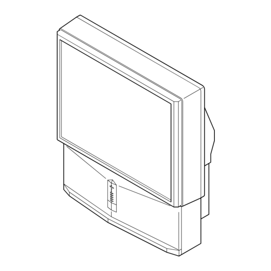
Page 150: Adjusting Colour Registration (Convergence)
First Time Operation - Menu System Adjusting Colour Registration (Convergence) Due to the earth’s magnetism, the picture might become undefined and you could see different colours on the outlines of the images. In that case, proceed as follows. Auto converge the Red, Green, and Blue Lines Press on the mark , on the front of the projection TV to reveal the... -
Page 151: On Screen Display Menus Guide
Menu System On Screen display Menus Guide Picture Adjustment Picture Adjustment Picture Mode Personal Picture Mode Personal Contrast Contrast Brightness Brightness Colour Refer to the section Colour Sharpness Sharpness Reset "Adjusting the Picture” Reset Noise Detection Noise Detection Digital Mode DRC 50 Digital Mode DRC 50... -
Page 152: Adjusting The Picture
Menu System Adjusting the Picture Although the picture is adjusted at the factory, you can modify it to suit your own taste. Press the MENU button on the remote control to display the menu Picture Adjustment VIDEO on the screen. Picture Mode Personal Contrast... -
Page 153: Adjusting The Sound
Menu System Adjusting the Sound Although the sound is adjusted at the factory, you can modify it to suit your own taste. Press the MENU button on the remote control to display the menu Picture Adjustment VIDEO on the screen. Picture Mode Personal Contrast... - Page 154 Menu System Push the joystick to $, 4, Z or z to alter the selected item, then VIDEO press the OK button to store the new adjustment. Repeat steps 3 and 4 to alter the other items. Press the MENU button to exit and return to the normal TV screen. Changing Sound Mode Quickly You can quickly change Sound mode without entering the Sound Control menu screen.
-
Page 155: Using The Features Menu
Menu System Using the Features Menu Using the Features menu you can: a) Select if you want to listen to the sound from the projection TV directly or through an external amplifier. b) Select a time period after which the projection TV switches itself into standby mode. c) Lock the buttons on the projection TV set. -
Page 156: Manually Tuning The Tv
Menu System Manually Tuning the TV Use this function to preset channels (TV Broadcast) or a video input source one by one to the programme order of your choice. Picture Adjustment Press the MENU button on the remote control to display the Picture Mode Personal VIDEO... -
Page 157: Labelling A Channel
Menu System Labelling a channel Names for channels (TV Broadcasts) are usually taken automatically from Teletext if available. You can however name a channel or an input video source using up to five characters (letters or numbers). Using this function, you can easily identify which channel (TV Broadcasts) or video source you are watching. -
Page 158: Skipping Programme Positions
Menu System Skipping Programme positions You can programme this projection TV to skip any unwanted programme numbers when they are selected with the PROGR +/- buttons. To cancel this function afterwards, proceed in the same way as described below by selecting Off instead of On in step 6. Press the MENU button on the remote control to display the menu Picture Adjustment VIDEO... -
Page 159: Using The "Further Programme Preset" Function
Menu System Using the "Further Programme Preset" function With this feature you can: a) Individually attenuate the strength of a channel signal in case of a strong local aerial signal (striped picture). b) Individually adjust the volume level of each channel. c) Even normally the automatic fine tuning (AFT) is operating, however you can manually fine-tune the TV to obtain a better picture reception if the picture is distorted. -
Page 160: Inputting Your Personal Id
Menu System Inputting Your Personal ID You can programme this projection TV with a personal code, using up to eleven characters (letters and numbers). Then using this fuction it will be possible to identify your projection TV if it was ever stolen. This code can only be input once! Make sure to write it down in this instruction manual. -
Page 161: Using The Demo Mode
Menu System Using the Demo Mode This function provides an overview of some of the features available on your projection TV. Press the MENU button on the remote control to display the menu Picture Adjustment VIDEO Picture Mode Personal on the screen. Contrast Brightness Colour... -
Page 162: Adjusting The Picture Geometry For An Rgb Source
Menu System Adjusting the picture geometry for an RGB source When connecting an RGB source, such as a DVD player, to the Scart connector :1/ you may need to readjust the geometry of the picture. Press the … button repeatedly on the remote control until the …... -
Page 163: Labelling Of Input Sources
Menu System Labelling of Input Sources This function enables you to designate a name to the optional equipment you have connected to the sockets of this projection TV. This name can contain up to 5 characters (letters or numbers). Press the MENU button on the remote control to display the menu Picture Adjustment VIDEO Picture Mode... -
Page 164: Using Multi Pip (Picture In Picture)
Menu System Using Multi PIP (Picture In Picture) Multi PIP (Picture in Picture) mode displays a succession of 12 still pictures and a 13th that is live. You can manually select which channel you wish to watch, either full-screen or in the PIP. Press the button on the remote control to select the PIP mode. -
Page 165: Selecting A Teletext Page
Teletext Teletext Most TV channels broadcast information via Teletext. The index page of the teletext service (usually page 100) gives you information on how to use the service. ! Please use a TV channel with a strong signal, otherwise there may be Teletext errors. Switching Teletext on and off Select the TV channel which carries the teletext service you want TELETEXT... - Page 166 Teletext Using the Teletext menu VIDEO With Teletext switched on, press the MENU button on the remote Teletext control to display the teletext menu on the TV screen. Top / Bottom / Full Push the joystick to 4 or $ to select your chosen item, then push to z Text Clear Reveal to display the relevant sub menu.
-
Page 167: Nextview
* In some cases, you may also need to push the joystick to Z to Tue 07. 04 .98 Star Wars Super RTL 10:35 - 12:45 display the Sony electronic programme guide. Werner - Beinhart Pro 7 10:20 - 12:00 Flui grüsst den Rest der Welt... - Page 168 NexTView Using the Long Info menu VIDEO With this menu screen, you can set timers or record selected programmes. Push 4 or $ to select a future programme in the programme list column. Press the OK button to display the Long Info menu on the TV screen.
-
Page 169: Optional Connections
Optional Connections Connecting Optional Equipment Using the following instructions, you can connect a wide range of optional equipment to your projection TV. Rear of projection TV Front of projection TV S.VHS/Hi8/DVC camcorder Dolby To avoid picture Surround Amplifier distortion: • Do not connect equipment to F and G connectors at... -
Page 170: Using Optional Equipment
Optional Connections Using Optional Equipment Additional Information when connecting equipment Connecting a VCR We recommend you connect your VCR to the B or C socket using a scart lead. If you do not have a scart lead, use the “Manually Tuning the TV”... -
Page 171: Smartlink
"Using the Further Programme Preset function" of this instruction manual. For more information on Smartlink, please refer to the Instruction Manual of your VCR. Remote Control of other Sony Equipment Using the buttons underneath the cover of the remote control you can control other Sony equipment. -
Page 172: Additional Information
Additional Information Optimum Viewing Area For the best picture quality, try to position the projection TV so that you can view the screen from within the areas shown below. Horizontal viewing area 60º 60º (Optimum viewing position) Vertical viewing area 20º... -
Page 173: Specifications
F2-F10, B-Q, F21-F69 KP-53PS1: Approx. 1218 x 1419 x 606 mm KP-48PS1: Approx. 1106 x 1336 x 562 mm Projected picture size KP-48PS2: Approx. 1091 x 1335 x 580 mm KP-61PS1, KP-61PS2: 61 inches (approx. 154 cm measured diagonally) Weight KP-53PS1: KP-61PS1, KP-61PS2: Approx. -
Page 174: Troubleshooting
Noisy picture when viewing TV channel please refer to the section "Using the Further Programme Preset function" • Replace the batteries. Remote control does not function • Contact your nearest Sony service centre. The standby indicator on the TV flashes. -
Page 175: Television Channel Number Guide For United Kingdom
Additional Information Television Channel Number Guide for United Kingdom Only the main transmitters are listed. Information regarding the regional sub-relay channel numbers can be obtain by connecting The BBC Engineering Information Dept. (0181) 752 5040. MAIN TRANSMITTERS BBC1 BBC2 London & South East Bluebell Hill Crystal Palace Dover... - Page 176 Sony España, S.A. Printed in Spain Ecological Paper-Totally Chlorine Free...