
Related Manuals for Motorola EX-3524


Summary of Contents for Motorola EX-3524
- Page 1 Motorola Solutions EX-3524/EX-3548 Layer 2 Gigabit Ethernet PoE/PoE+ Switch Installation Guide...
- Page 2 EX-3524/EX-3548 Layer 2 Gigabit Ethernet PoE/PoE+ Switch MOTOROLA SOLUTIONS and the Stylized M Logo are registered in the US Patent & Trademark Office. © Motorola Solutions, Inc. 2014. All rights reserved.
-
Page 3: Table Of Contents
Installation Guide 1.0 Introduction ............5 1.1 Unpacking . - Page 4 5.7.1 Turkish WEEE Statement of Compliance ......32 6.0 Motorola Solutions Support Center ....... . . 33...
-
Page 5: Introduction
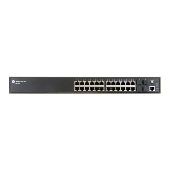
Installation Guide 1 Introduction The Motorola Solutions EX-3524 and EX-3548 are Gigabit Ethernet Layer 2 switches with either 24 or 48 10/100/1000-BASE-T ports, and four Small Form Factor Pluggable (SFP) transceiver slots for fiber connectivity. The switches are built with leading-edge technology to deliver reliable high-performance connectivity for your data network. -
Page 6: Warnings
Dispose of used batteries according to the instructions. • Motorola strongly recommends the use of an Uninterruptible Power Supply (UPS) that supports the EX-3524/EX-3548 switch power rating. Not using a UPS can result in data loss or equipment damage due to a power surge or power failure. -
Page 7: Site Preparation
Installation Guide 1.4 Site Preparation • Consult your site survey and network analysis reports to determine specific equipment placement, port capacity, power drops, and so on. • Assign installation responsibility to the appropriate personnel. • Identify where all installed components are located. •... -
Page 8: Specifications
Form factor 1U rack mount Dimensions (WxDxH) EX-3524: 44.0 x 28.0 x 4.4 cm (17.32 x 11.00 x 1.73 in) EX-3548: 44.0 x 40.9 x 4.4 cm (17.32 x 16.10 x 1.73 in) Weight EX-3524: 3.6 kg (7.83 lb) EX-3548: 6.6 Kg (14.55 lb) 2.2 Environmental Specifications... -
Page 9: Power Cord Specifications
Installation Guide 2.4 Power Cord Specifications A power cord is not supplied with the EX-3524/EX3548 switch. Use only a correctly rated power cord certified (as appropriate) for the country of operation. 2.4.1 Power Protection • If possible, use a circuit dedicated to data processing equipment. Commercial electrical contractors are familiar with wiring for data processing equipment and can help with the load balancing of these circuits. -
Page 10: Port Leds
EX-3524/EX-3548 Layer 2 Gigabit Ethernet PoE/PoE+ Switch 2.5.1 Port LEDs For information on port status LED indicators, see Port Status LEDs on page 2.5.2 10/100/1000BASE-T RJ-45 Ports The switch contains 24 10/100/1000BASE-T RJ-45 ports that support 10/100/1000BASE-T copper links to other devices. -
Page 11: Ac Power Socket
Installation Guide 2.5.9 AC Power Socket The switch requires a 100-240 VAC, 50-60 Hz AC power source. For more information on the switch power input, how to connect it, and how to power-on the switch, see Power and Grounding on page... -
Page 12: Led Codes
EX-3524/EX-3548 Layer 2 Gigabit Ethernet PoE/PoE+ Switch 2.6 LED Codes 2.6.1 System Status LEDs The diagnostic and power LEDs located on the front panel are shown below and described in the following table: Condition Status DIAG Green Solid System diagnostic test completed successfully... -
Page 13: Port Status Led
Installation Guide 2.6.2 Port Status LEDs The switch includes LEDs for each port to indicate link status and network activity. The port LEDs are shown below and described in the following table: Condition Status 1000BASET RJ-45 Ports (1 - 24 or 1 - 48) Link/Activity On/Blinking Amber Port has a valid 10/100 Mbps link. -
Page 14: Hardware Setup
EX-3524/EX-3548 Layer 2 Gigabit Ethernet PoE/PoE+ Switch 3 Hardware Installation The switch is designed to be installed in either a standard 19-inch equipment rack or simply placed on a suitable desktop or shelf surface. If you will mount your switch in a rack then plan your rack installation and install the switch chassis in the rack. - Page 15 Installation Guide 2. Use the supplied rack mounting screws to secure the switch in the rack. 3. Connect an external AC power source to the AC power socket.
- Page 16 EX-3524/EX-3548 Layer 2 Gigabit Ethernet PoE/PoE+ Switch 4. Verify basic switch operation by observing the system LEDs. For normal operation, both the DIAG and PWR LEDs should be solid green. 5. Install the SFP transceivers and connect the cables to the port interfaces.
-
Page 17: Shelf Or Desktop Installation
Installation Guide 3.2 Shelf or Desktop Installation The switch can be installed on any flat surface such as a desktop or shelf. To mount the switch on a flat surface: 1. Attach the four adhesive feet to the bottom of the switch. 2. -
Page 18: Power And Grounding
The switches require power from an external AC power supply that can provide 100 to 240 VAC, 50-60 Hz. A standard AC power socket is located on the rear panel EX-3524 (left) and EX-3548 (right) of the each switch. The rear panel of the switch chassis includes a single hole grounding terminal. It must be connected to ground to ensure proper operation and to meet electromagnetic interference (EMI) and safety requirements. -
Page 19: Port Connections
Installation Guide 3.4 Port Connections 3.4.1 Installing SFP Transceivers The switch provides slots for optional (not provided) SFP transceivers. The supported transceiver types are listed below: • 1000BASE-SX • 1000BASE-LX • 1000BASE-LH • 1000BASE-FX • 1000BASE-T SPF transceivers are hot-swappable. The switch does not need to be powered off NOTE before installing or removing the transceiver. -
Page 20: Connecting Twisted-Pair Cables
EX-3524/EX-3548 Layer 2 Gigabit Ethernet PoE/PoE+ Switch 4. Slide the transceiver into the slot until it clicks into place. If you do not immediately connect a cable to the port, use a rubber protective cap to keep the transceiver optics clean. -
Page 21: Cable Requirements
For the EX-3524, the total PoE power delivered by all ports cannot exceed the 390 W power budget. This means that up to 12 ports can supply a maximum 30 W of power simultaneously to connected devices, or all 24 ports can supply a maximum of 15.4 W. -
Page 22: Connecting To Sfp Ports
EX-3524/EX-3548 Layer 2 Gigabit Ethernet PoE/PoE+ Switch 2. Attach the other end to an available port on the switch. Ensure each twisted pair cable does not exceed 100 meters (328 ft) in length. 3. As each connection is made, the Link LED (on the switch) corresponding to each port will turn on green to indicate that the connection is valid. - Page 23 Installation Guide To connect cables to SFP transceiver ports: 1. Remove and keep the fiber port’s rubber plug. When not connected to a fiber cable, the rubber plug should be replaced to protect the optics. 2. Check that the fiber terminators are clean. You can clean the cable plugs by wiping them gently with a clean tissue or cotton ball moistened with a little ethanol.
-
Page 24: Switch Management
EX-3524/EX-3548 Layer 2 Gigabit Ethernet PoE/PoE+ Switch 4 Switch Management The RJ-45 Console port on the front panel of the switch is used to connect a console device to the switch for out-of-band console configuration. The console device can be a PC or workstation running a VT-100 terminal emulator, or a VT-100 terminal. - Page 25 115200 bps, 8 data bits, 1-stop bit and no parity 4. Log in to the command-line interface (CLI) using one of the default user login settings: • username: admin • password: motorola • username: guest • password: guest The guest default user login will only allow a user to view switch parameter data.
-
Page 26: Resetting The Switch
EX-3524/EX-3548 Layer 2 Gigabit Ethernet PoE/PoE+ Switch 4.2 Resetting the Switch The Reset button located on the rear panel of the switch can be used to restart the device and set the configuration back to either the current saved configuration file or the factory default settings. -
Page 27: Regulatory Information
This device is approved under Motorola Solutions, Inc. This guide applies to the following model numbers: EX-3524 and EX-3548. All Motorola devices are designed to be compliant with rules and regulations in locations where they are sold and will be labeled as required. -
Page 28: Pse Alarm
EX-3524/EX-3548 Layer 2 Gigabit Ethernet PoE/PoE+ Switch Japan Voluntary Control Council for Interference (VCCI) Class A ITE VCCI-A Korea Warning Statement for Class A ITE Chinese Warning Statement for Class A ITE 5.5 PSE Alarm 5.6 Power Cord Safety Please read the following safety information carefully before installing the switch: Warning: Installation and removal of the unit must be carried out by qualified personnel only. - Page 29 Installation Guide France and Peru only This unit cannot be powered from IT† supplies. If your supplies are of IT type, this unit must be powered by 230 V (2P+T) via an isolation transformer ratio 1:1, with the secondary connection point labelled Neutral, connected directly to earth (ground).
- Page 30 EX-3524/EX-3548 Layer 2 Gigabit Ethernet PoE/PoE+ Switch France et Pérou uniquement: Ce groupe ne peut pas être alimenté par un dispositif à impédance à la terre. Si vos alimentations sont du type impédance à la terre, ce groupe doit être alimenté par une tension de 230 V (2 P+T) par le biais d’un transformateur d’isolement à...
- Page 31 Installation Guide Der Betrieb dieses Geräts erfolgt unter den SELV-Bedingungen (Sicherheitskleinstspannung) gemäß IEC 60950. Diese Bedingungen sind nur gegeben, wenn auch die an das Gerät angeschlossenen Geräte unter SELV-Bedingungen betrieben werden. Stromkabel. Dies muss von dem Land, in dem es benutzt wird geprüft werden: Etats-Unis et Le cordon doit avoir reçu l’homologation des UL et un certificat de la CSA.
-
Page 32: Waste Electrical And Electronic Equipment (Weee)
EX-3524/EX-3548 Layer 2 Gigabit Ethernet PoE/PoE+ Switch 5.7 Waste Electrical and Electronic Equipment (WEEE) English: For EU Customers: All products at the end of their life must be returned to Motorola Solutions for recycling. For information on how to return product, please go to: http://www.motorolasolutions.com/recycling/weee. -
Page 33: Turkish Weee Statement Of Compliance
Solutions-yhtiöön, kun tuotetta ei enää käytetä. Lisätietoja tuotteen palauttamisesta on osoitteessa http://www.motorolasolutions.com/recycling/weee. Dansk: Til kunder i EU: Alle produkter skal returneres til Motorola Solutions til recirkulering, når de er udtjent. Læs oplysningerne om returnering af produkter på: http://www.motorolasolutions.com/recycling/weee. Ελληνικά: Για πελάτες στην Ε.Ε.: Όλα τα προϊόντα, στο τέλος της διάρκειας ζωής τους, πρέπει να επιστρέφονται... - Page 34 • Model number or product name • Software type and version number Motorola Solutions responds to calls by e-mail, telephone, or fax within the time limits set forth in support agreements. If you purchased your product from a Motorola Solutions business partner, contact that business partner for support.
- Page 35 Installation Guide...
- Page 36 Schaumburg, IL 60196-1078, U.S.A. http://www.motorolasolutions.com MOTOROLA, MOTO, MOTOROLA SOLUTIONS and the Stylized M Logo are trademarks or registered trademarks of Motorola Trademark Holdings, LLC and are used under license. All other trademarks are the property of their respective owners. © 2014 Motorola Solutions, Inc. All Rights Reserved.