Table of Contents
Advertisement
This service manual provides a variety of service
information. It contains the mechanical structure of
the CD-ROM Drive together with mechanical
adjustments and the electronic circuits in schematic
• Enhanced IDE interface
• Internal 5.25 inch, halfheight CD-ROM Drive
• Fast 75ms Average Access Time
• Max 7,200KB/sec Sustained Transfer rate
• Photo-CD Multisession Disc Spec compliant
• Multimedia MPC-3 Spec compliant
• Power Tray Loading/Ejection Mechanism
• 3 Way Eject support
(Software, O/C Button, Emergency Eject)
• Closed Enclosure
• Built-in ATAPI Interface Controller
1. MODEL: CRD-8483B
1) SUPPORTED SYSTEM
• IBM Compatible 486SX or Above (With PIO mode 4 recommended)
2) SUPPORTED OS
• MS-DOS Version 3.1 or Higher
• Windows '95/'98
3) GENERAL PERFORMANCE
• Data Transfer Rate .........................................................................................Sustained Data Transfer Rate
• Data Buffer Capacity.....................................................................................................................128 kbytes
• Access Time...................................................................................................Random Access Time : 75 ms
4) POWER REQUIREMENTS
• Voltage ......................................................................................................................................+5V DC +5%
• Ripple ..................................................................................................................+5V : Less than 100mVp-p
• Current .......................................................................................................................+5V : 0.9A (Maximum)
5) AUDIO PERFORMANCE
• Frequency Response.....................................................................................................20Hz~20KHz(+3dB)
• S/N Ratio (IHF-A+20 KHz LPF) .......................................................................75 dB (Typical at 1 KHz 0dB)
• T.H.D. (IHF-A+20 KHz LPF) ............................................................................0.05% (Typical at 1 KHz 0dB)
• Channel Separation (IHF-A+20 KHz LPF) .............................................................................75 dB (Typical)
• Output Voltage (1kHz 0dB) 47KΩ Load.................................................................................0.7Vrms + 10%
• Headphone Level (1kHz 0dB) 33Ω Load...............................................................................0.6Vrms + 20%
INTRODUCTION
GENERAL FEATURE
SPECIFICATIONS
• Solaris Ver 2.4 or Higher
• Linux slackware Ver 2.3
form. This CD-ROM Drive was manufactured and
assembled under our strict quality control standards
and meets or exceeds industry specifications and
standards.
• Software Volume Control
• 8 Times Digital Filter for CD Audio
• Front panel Volume Control for Headphone Output
• Built-in MODE-1 ECC/EDC
• MTBF 125,000h POH (at 10% Utilization)
• PIO Mode 4 & Multi DMA Mode 2 support
• Horizontal or Vertical Mounting
• Digital audio output connector
• Digital audio through ATAPI Interface
• Subcode (P-W) through ATAPI Interface
• Spin-down Mode for energy saving
• Windows NT 4.0 or later
• OS/2 Warp (Ver 3.0)
22Times Speed (Inner side) : 3,300 kbytes/sec
48 Times Speed (max., Outer side) : 7,200 kbytes/sec
+12V DC +5%
+12V : Less than 100mVp-p
+12V : 1.5A (Maximum)
70 dB (Limit at 1 KHz 0dB)
0.15% (Limit at 1 KHz 0dB)
70 dB (Limit)
3
Advertisement
Table of Contents

Related Manuals for LG CRD-8483B


Summary of Contents for LG CRD-8483B
-
Page 1: Specifications
• Subcode (P-W) through ATAPI Interface • Built-in ATAPI Interface Controller • Spin-down Mode for energy saving SPECIFICATIONS 1. MODEL: CRD-8483B 1) SUPPORTED SYSTEM • IBM Compatible 486SX or Above (With PIO mode 4 recommended) 2) SUPPORTED OS • MS-DOS Version 3.1 or Higher •... -
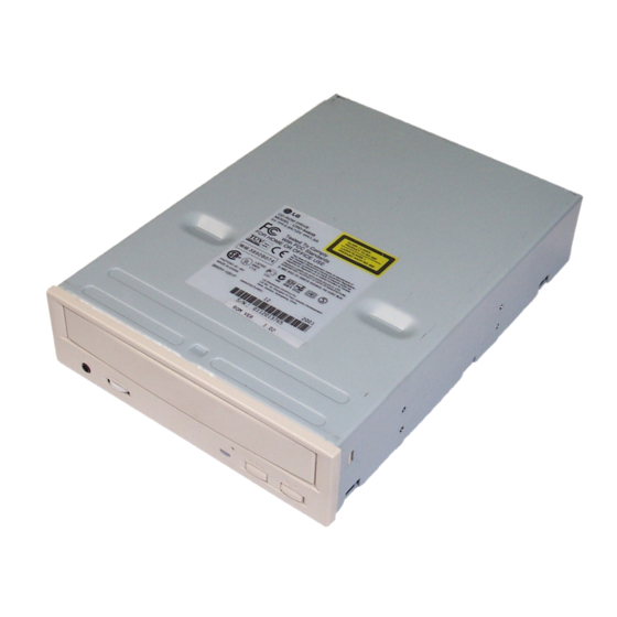
Page 2: Location Of Customer Controls
LOCATION OF CUSTOMER CONTROLS FRONT COMPACT Figure 1. Front View Headphone Jack Play/Skip Button 3.5mm jack for monitoring the audio signal from audio When an Audio CD is in the Disc Drawer, pressing CDs. this button will start playing audio CDs from the first track. -
Page 3: Troubleshooting Guide
TROUBLESHOOTING GUIDE 1. Initial Lead-in Operation Reset or Power-On. LED Flickers. Pick-Up moves to the inner-Track. Laser on the Pick-Up lights. Focus Search (through moving up and down the lens of Pick-Up) Focus Servo On (FEO(TP15) signal generation) Rotate disc. Tracking Servo On (TEI(TP14) Signal generation) Spindle Servo On (DMSO(TP25) Signal generation) Read TOC Area (LED Flickers) - Page 4 3. Troubleshooting Guide A. LED doesn’t light. Check Power Voltage (TP1:3.3V, TP2:12V) Check the power input Reference Voltage pattern. [TP5:VREF(2V), TP6:V2REF(4V) and GND.] Is the CLOCK Frequency of Does “H” output in IC501 pin IC501 pin 33.86MHz? Check and replace R705, R706, Q701 Check IC501.
- Page 5 B. Pick-Up doesn’t move to the inner track. Do the signals appear at IC501 Check IC501. (Refer to Fig. B-1.) Check the pattern from Does “H” output at IC201 IC501 pin to IC201 Is the 2V at IC201 pin Replace IC101. Do the signals appear in PN301 pin? Replace IC201.
- Page 6 C. The Laser of Pick-Up doesn’t light. Does “High” output at IC101 Replace IC501. Is the voltage of IC101 pin Check Q101, C101, C102 and then replace IC101. (LD0) 2V? Check Pick-Up FFC, PN101. D. The Pick-UP lens doesn’t move up and down. Check the pattern from Does the focus search signal IC501 pin...
- Page 7 Check the pattern from of IC201 to of PN101. Replace PN101 or Pick-Up Check the PN101, Pick-Up FFC. FFC. Replace the Pick-Up. TP10(F+) TP11(F-) (FAO) Fig. D-1. F0S0 Signal Fig. D-2. Focus Search Signal...
- Page 8 E. Disc doesn’t rotate. Does the signal appear at Does the signal appear at FEO (TP15) when the Replace Pick-Up. F + (TP10) during focus IC501 pin opened? search? (Refer to Fig. E-1.) Replace IC501. Do the signal appear at Replace IC501.
- Page 9 TP15: TP15: S-Curve Fig. E-1. S-Curve Fig. E-2. FEO Signal TP25: DMS0 Fig. E-3. DMS0 Signal...
- Page 10 F. TOC isn’t read. Is the Focus Servo ON? Does A, B, C, D signal (Does FEO (TP15) signal appear at IC101 pin appear?) Replace IC101. Refer to C. (The Laser of Pick-Up Is the Tracking Servo ON? Does E, F signal appear doesn’t light.) (Does TEI (TP14) signal at IC101 pin...
- Page 11 G. During Audio CD play, LED flickers, but Speaker is silent. Does Audio signal appear Replace IC501. at IC501 pin (Refer to Fig. G-1.) Does “H” signal appear at Check the IC501 pin and then replace IC501? IC501 pin Does Audio signal appear Is the voltage of IC701 Replace IC701.
- Page 12 Is the connection between JK801 (or Audio Check the JK801 and Line out connector) and Audio line pattern. Line (or Jack) normal? Check your sound card, Audio Cable, Speaker, Volume and Headphone Jack. PIN3 of IC601 PIN12 of IC601 Fig. G-1. Audio Signal...
-
Page 13: Cabinet And Circuit Board Disassembly
DISASSEMBLY 1. CABINET and CIRCUIT BOARD 1-3. Cabinet and Main Circuit Board A. Remove the Cabinet in the direction of arrow (4). DISASSEMBLY (See Fig. 1-3) 1-1. Bottom Chassis B. Release 2 hooks (a) and remove the CD Tray. A. Release 4 screws (A) and remove the Bottom C. - Page 14 PHOTO DIODE STRUCTURE OF THE PICK-UP (1) Focus Error Signal –> (A+C)-(B+D) (Control the Pick-up’s up and down to focus on the Disc) (2) Tracking Error Signal –> (E-F) (Control the Pick-up’s left and right shift to find the track on the Disc) (3) RF Signal –>...
-
Page 15: Block Diagram
IC INTERNAL BLOCK DIAGRAM AND PIN DESCRIPTION • IC101 (MT1136AE) : RF Amplifier IC I-V converts and amplifies the signal received from the pick-up and then applies to DSP part of one- chip IC (IC501). Block Diagram Summation and VGA RFGC (Variable-gain Amp) CSOSEL... -
Page 16: Pin Description
Pin Description Pin No. Symbol Type Description Power Negative power supply. TEST Test pin No connect. Analog Input Voltage for monitor laser diode photo power. Analog Power Laser diode control output. CSPI Analog Input Central Servo input 1 CSNI Analog Input Central Servo input 2. - Page 17 • IC201 (M63021FP) : Drive IC (Spindle/Servo Actuator) Rotates the Spindle Motor by receiving MDP signal from IC501. Generates the signal to drive Focus Actuator Coil, Tracking Actuator Coil, Sled Motor, and Stepping Motor by Control Signal input from DSP and u-COM. Block Diagram Reverse Detect...
- Page 18 • IC501 (MT1198CE) : DSP+ATAPI DECODER+µ-COM Block Diagram Mega interface VBDPLL PDM & and GPIO Control PLLVSS Reset LPIO DVDD RFRP Circuitry Servo LPIN Data Slicer Circuit 1PLL LPFO and Data PLL Servo Decoder & UP LPFN DD10 Clock Generator IREF DD11 RSPC...
- Page 19 • IC501 MT1198CE Pin Description Pin No. Symbol Type Description Data PLL Interface VBDPLL Anallog Output Reference voltage PLLVSS Ground Ground pin for data PLL and related analog circuitry. LPIO Analog Output The output of VCO integrator. LPIN Analog Input The negative input terminal of VCO integrator.
- Page 20 Pin No. Symbol Type Description X’tal Interface XTALI Input X’tal input. The working frequency is 33.8688 MHz. XTALO Output X’tal output. DRAM Interface DVDD Power(5V) Power pin for internal digital circuitry. DGND Ground Ground pin for internal digital circuitry. 58, 60, 62, RD[15:8]/ TTL I/O, Slew rate Buffer RAM Data/Versatile Input/ Output.
- Page 21 Pin No. Symbol Type Description VPVSS Ground Ground pin for varipitch VCO circuitry. Host Interface DEVSEL TTL Input Device Select. Cleared to zero indicates the MT1198 is master device. 50K pull_up Set to one indicates the MT1198 is slave device. DASP_ TTL I/O Device Active/Device 1 Present.
- Page 22 Pin No. Symbol Type Description DMARQ TTL Output DMA Request. This signal, used for DMA data transfer, is asserted by the MT1198 when it is ready to transfer data to or from the host. 116~121, DD[15:0] TTL I/O pull_up/ Device Data. This is the 8-bit or 16-bit bi-directional data bus to the host. pull_down The lower 8 bits, DD0-DD7, are used for 8-bit data transfers.
- Page 23 Pin No. Symbol Type Description FMO2 Analog Output Programming PWM output. For stepping motor (sledge) application. ENDM TTL Output Enable/disable disk motor. A logical high enables disk motor. Analog Output Disk motor control output. PWM output. TEBC Analog Output Tracking error balance control. PWM output. RFGC Analog Output RF data gain control.
- Page 24 BLOCK DIAGRAM * MODEL: CRD-8483B MT1136AE RF Amp. DRAM 33.86MHz Optical Disc Pick-up Motor unit MT1198CE I/F Cable DSP+Decoder+ System controller SPINDLE FOCUS TRACKING SLED LOADING MOTOR COIL COIL MOTOR MOTOR M63021FP R-ch MOTOR DRIVE FLASH L-ch MEMORY Line-out 3.3V Reg.
- Page 25 EXPLODED VIEW PBM00 (MAIN C.B.A)