Dell Z9500 Installation Manual
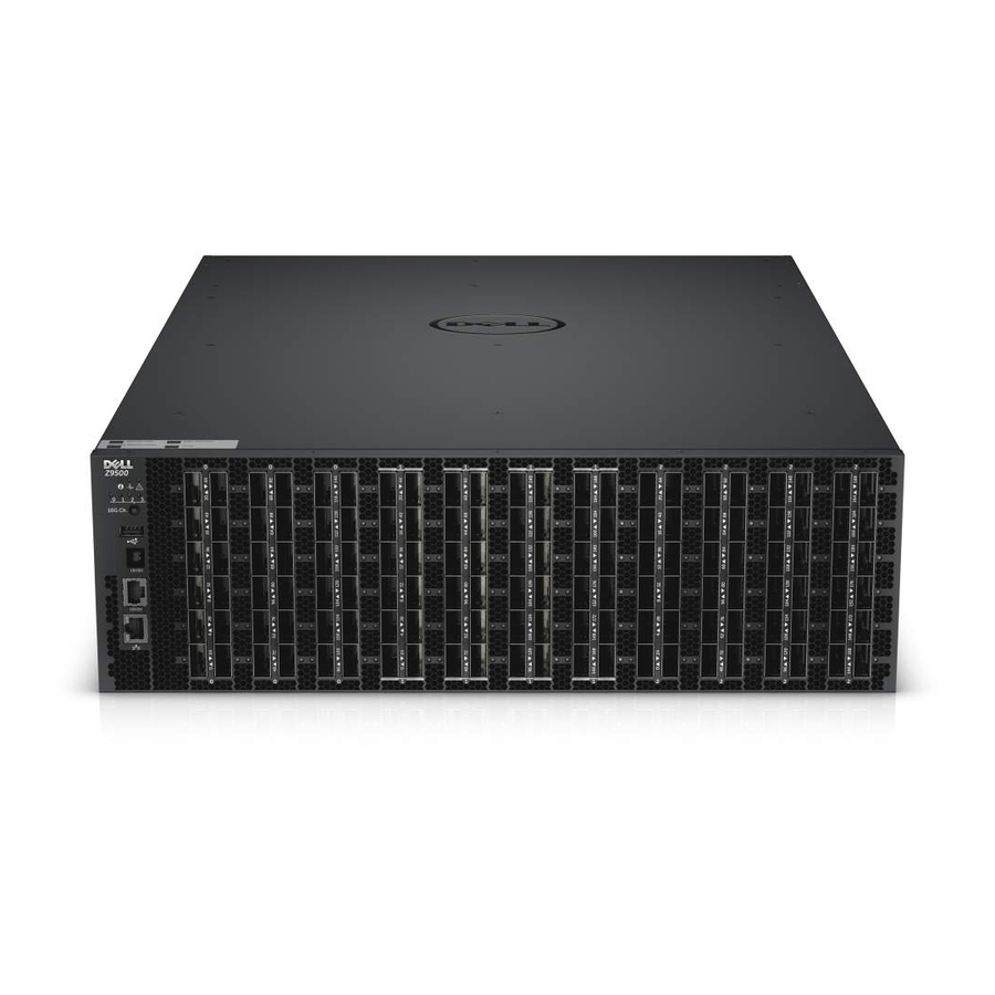
Z9500 switch
Hide thumbs
Also See for Z9500:
- Command reference manual (1905 pages) ,
- Reference manual (1849 pages) ,
- Configuration manual (953 pages)
Table of Contents
Advertisement
Quick Links
Advertisement
Table of Contents

Related Manuals for Dell Z9500


Summary of Contents for Dell Z9500
- Page 1 Dell Networking Installation Guide for the Z9500 Switch...
- Page 2 WARNING: A WARNING indicates a potential for property damage, personal injury, or death. Copyright © 2014 Dell Inc. All rights reserved. This product is protected by U.S. and international copyright and intellectual property laws. Dell ™...
-
Page 3: Table Of Contents
Attaching the Mounting Brackets ................20 Attaching the Static-Rails Mounting Brackets ....................20 Installing the Dell Static Rails System Identifying the Rail Kit ContentsInstalling and Removing Tool-less Rails (Square- ..20 Hole)Installing and Removing Tooled Rails (Threaded-Hole Racks or Round-Hole Racks) .................. - Page 4 ....................36 Splitting QSFP+ Ports to SFP+ Ports ....................37 Important Points to Remember .................37 Supplying Power and Powering Up the System ............................37 AC Power 7 Technical Specifications..................39 8 Agency Compliance....................41 ............41 USA Federal Communications Commission (FCC) Statement ..............
-
Page 5: About This Guide
After you have completed the hardware installation and power-up of the Z9500, for software configuration information, refer to the Dell Networking Configuration Guide for the Z9500 Switch and for Command Line Interface (CLI) information, refer to the Dell Networking Command Line Reference Guide for the Z9500 Switch. -
Page 7: Introduction
This document provides basic information about installing the Z9500 switch. For information about how to configure and monitor switch features, refer to the Dell Networking Configuration Guide for the Z9500 Switch, which is available on the Dell Support website at http:// support.dell.com/manuals. -
Page 9: Unpacking The Switch
Before unpacking the switch, inspect the container and immediately report any evidence of damage. Verify that you have received your ordered items, including the following: WARNING: If any item is missing or damaged, contact your Dell Networking representative or reseller for instructions. - Page 10 Installing Fan Modules Securing Power Cables Installing the QSFP+ Optics Installing the Cable Management System Supplying Power and Powering Up the System Unpacking the Switch...
-
Page 11: Hardware Overview
• Depth: 32 inches (812.80 mm) The Z9500 has a chassis design with 5280Gbps switching bandwidth. The system also provides one DB9 RS-232 console port with YOST RJ-45 pinout and a dedicated Ethernet service port for out-of-band (OOB) management functions. -
Page 12: Utility Panel
Dell Networking Configuration Guide for the Z9500 Switch. As shown in the following figure, the Z9500 includes LED displays on the I/O and Utility side of the chassis. When the Z9500 powers up or reloads, the status LED on the power supplies are solid green. - Page 13 Figure 3. System LED Displays (I/O Panel) Alarm LED System status LED System locator LED 10GbE channel selection indicator 10GbE channel selector button Management Port Activity LED Management Port Status LED Table 1. System LED Displays (I/O Panel) Label LED Color/ Description Display •...
- Page 14 Label LED Color/ Description Display • Green solid • Traffic on Management Port Figure 4. 40GbE Port LEDs (I/O Panel) Port LED NOTE: In 40GbE mode, the front end ports are “solid green” color in operational state. However, if the port is configured to work in 10GbE mode, then the front end ports are “solid amber” color in operational state.
- Page 15 Figure 5. System LED Displays (Utility Panel) Fan status LED PSU status LED Table 3. System LED Displays (Utility Panel) Label LED Color/Display Description • Green solid • Normal operation PSU status LED • Amber Solid • Minor/Major alarms • •...
-
Page 17: Site Preparation
Site Preparation The Z9500 is suitable for installation as part of a Common Bond Network (CBN). It can be installed in: • network telecommunication facilities • data centers • other locations where the National Electric Code (NEC) applies This chapter contains the following sections: •... -
Page 18: Storing Components
WARNING: ESD damage can occur when components are mishandled. Always wear an ESD- preventive wrist or heel ground strap when handling the Z9500 and its accessories. After you remove the original packaging, place the Z9500 and its components on an anti-static surface. -
Page 19: Z9500 Installation
Z9500 Installation To install the Z9500, follow these steps: Assemble 4-Post Rack Frame Attaching the Mounting Brackets Installing the Dell Static Rails System Securing the Chassis Ground Installing Fan Modules Installing AC Power Supplies Securing Power Cables Installing the Cable Management System... -
Page 20: Attaching The Mounting Brackets
Screws Static-rail mounting bracket Installing the Dell Static Rails System Dell Networking provides the Static Rails rack mounting system so you can easily configure a rack to install the switch. Identifying the Rail Kit Contents Locate the components for installing the rail kit assembly: •... - Page 21 Repeat these steps to position and seat the front end piece on the vertical flange. NOTE: Make sure the blue release latch is closed. To remove the rails, pull on the blue release latch on each end piece and unseat the rail from the rack. Z9500 Installation...
- Page 22 Attach the left and right mounting rails to the front vertical rack flanges using two pairs of screws. Slide the left and right rear brackets forward against the rear vertical rack flanges and attach them using two pairs of screws (3). Z9500 Installation...
-
Page 23: Mounting The Chassis In A Four-Post Rack
Power considerations — Connect only to the power source specified on the unit. When multiple electrical components are installed in a rack, ensure that the total component power ratings do not exceed the circuit capabilities. Overloaded power sources and extension cords present fire and shock hazards. Z9500 Installation... - Page 24 NOTE: The illustrations in this document are not intended to represent a specific switch. Installing and Removing the System For a Dell 4226 (1070 mm) cabinet, adjust the front vertical rail inside Dell 4226 cabinet to a depth of 6.5 inches as shown in the figure below.
- Page 25 Dell 4226 (1070 mm) cabinet outline Adjustable front vertical rail inside Dell 4226 cabinet 6.5 inches Align the system with rails and slide the system into rack. Tighten the screws on each side of the systems’s front panel (1). To remove the system from the rack, loosen the screws and slide the system out of the rack.
- Page 26 Additional screw to restrict front-back Main screw movement of the switch Z9500 Installation...
-
Page 27: Securing The Chassis Ground
Environmental Parameters section. Use M5 screws. Tighten the screws (torque should be between 18 and 24 inch/lbs). Connect the opposite end of the grounding cable to the nearest appropriate facility grounding post. Figure 6. Cable Connector Z9500 Installation... -
Page 28: Installing Fan Modules
To view the log messages, use the show logging command. For more information, refer to the System Logs chapters of the Dell Networking OS Command Line Reference Guide for the Z9500 Switch and Dell Networking OS Configuration Guide for the Z9500 Switch. -
Page 29: Installing Ac Power Supplies
To view the log messages, use the show logging command. For more information, refer to the System Logs chapters of the Dell Networking OS Command Line Reference Guide for the Z9500 Switch and Dell Networking OS Configuration Guide for the Z9500 Switch. - Page 30 Figure 8. Installing an AC Power Supply Release latch Slot 0 (for AC PSU 0) CAUTION: Fan tray modules must be inserted before powering up the switch. CAUTION: The switch has a high line-voltage requirement of minimum 200V. Z9500 Installation...
- Page 31 Ensure that the socket-outlet is located/installed near the equipment and is easily accessible. Repeat steps 1 through 3 above for all PSUs. NOTE: Ensure that the PSU is correctly installed. When you correctly install the PSU, the power connector is on the left side of the PSU. Z9500 Installation...
-
Page 32: Securing Power Cables
Using the cable management system, you can attach the maximum number of cables in Z9500 I/O ports. NOTE: The installation of the cable management system requires that you install these parts in the order presented in this document. -
Page 33: Installing The Cable Management System For Direct Attach Copper (Dac) Cables
Rack unit for DAC cable routing Insert a cable in a Z9500 port. then route the DAC cables up and along the line-card face between the larger pins directly above the card. Position the cables so they follow the channel marked in the figure below and exit to the right or left, depending on the chassis slot location. - Page 34 Figure 12. Routing DAC cables using the Cable Management System Pin rack unit for DAC cable routing Rack unit for DAC cable routing NOTE: To fully populate the cable management system in a 1070 mm cabinet, the maximum supported length of the DAC cable is 5 m. Z9500 Installation...
-
Page 35: Installing The Cable Management System For Optical Fibres
Installing the Cable Management System for Optical Fibres Insert an optical cable in a Z9500 port. then route the optical cable up and along the line-card face above the switch. Position the cables so they follow the channel marked in the figure below and exit to the right or left, depending on the chassis slot location. -
Page 36: Port Numbering Convention
The system supports splitting a single 40GbE QSFP+ port into four 10GbE SFP+ ports using one of the supported breakout cables. For a list of supported optics, contact your Dell Networking representative or reseller. • Configure the system to recognize the port mode change. -
Page 37: Important Points To Remember
Supply power to the system after the chassis is mounted in a rack or cabinet. CAUTION: The switch has a high line-voltage requirement of minimum 200V. Dell Networking recommends reinspecting your system prior to powering up. Verify that: • The equipment is properly secured to the rack. -
Page 39: Technical Specifications
Technical Specifications NOTE: Operate the product at an ambient temperature not higher than 40°C. Table 4. Chassis Physical Design Parameter Specifications Height 5.2 inches (132.08 mm) Width 17.4 inches (441.96 mm) Depth 32 inches (812.80 mm) Chassis weight with factory-installed components 122 pounds (Approximately) Rack clearance required •... -
Page 41: Agency Compliance
Properly shielded and grounded cables and connectors must be used in order to meet FCC emission limits. Dell Networking is not responsible for any radio or television interference caused by using other than recommended cables and connectors or by unauthorized changes or modifications in the equipment. -
Page 42: European Community Contact
Japan: VCCI Compliance for Class A Equipment WARNING: Use the AC power cords with Dell Networking equipment only. Do not use Dell Networking AC power cords with any unauthorized hardware. This is Class A product based on the standard of the Voluntary Control Council For Interference by Information Technology Equipment (VCCI). -
Page 43: Korean Certification Of Compliance
Korean Certification of Compliance Korean Package Label Safety Standards and Compliance Agency Certifications • CUS UL 60950-1, Second Edition • CSA 60950-1-03, Second Edition • EN 60950-1, Second Edition • EN 60825-1, First Edition • EN 60825-1 Safety of Laser Products — Part 1: Equipment Classification Requirements and User’s Guide •... -
Page 44: Product Recycling And Disposal
EEE on the environment and human health due to the potential presence of hazardous substances in EEE. Dell Networking products, which fall within the scope of the WEEE, are labeled with the crossed-out wheelie-bin symbol, as shown above, as required by WEEE. -
Page 45: Technical Support
Contacting Technical Support The iSupport Website iSupport provides a range of documents and tools to assist you with effectively using Dell Networking equipment and mitigating the impact of network outages. Through iSupport you can obtain technical information regarding Dell Networking products, access to software upgrades and patches, and open and manage your Tech Support cases. -
Page 46: Requesting A Hardware Replacement
Using the Create Service Request form on the iSupport page (refer to Contacting Technical Support). b. Contacting Dell Networking directly by E-mail or by phone (refer to Contacting Technical Support). Provide the following information when using E-mail or phone: •... - Page 47 Technical Documentation Log in to iSupport and select the Documents tab. You can access this page without logging in using the Documentation link on the iSupport page. Contact Information E-mail: Dell- Force10_Technical_Support@Dell.com Web: http://support.dell.com/ Telephone: • USA: 1-866-965-5800 •...