Table of Contents
Advertisement
Quick Links
Advertisement
Table of Contents

Related Manuals for Dell Z9432F-ON


Summary of Contents for Dell Z9432F-ON
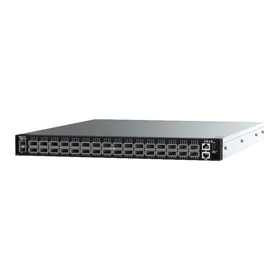
- Page 1 Dell EMC PowerSwitch Z9432F-ON Setup Guide September 2020 September 2020 Rev. A00...
- Page 2 A WARNING indicates a potential for property damage, personal injury, or death. © 2020 Dell Inc. or its subsidiaries. All rights reserved. Dell, EMC, and other trademarks are trademarks of Dell Inc. or its subsidiaries. Other trademarks may be trademarks of their respective owners.
-
Page 3: Table Of Contents
Site selection..................................6 Cabinet placement................................6 Rack mounting..................................7 Switch ground..................................7 Fans and airflow................................... 7 Power......................................7 Storing components................................7 Chapter 3: Z9432F-ON switch installation..................9 Unpack....................................9 Ground cable..................................9 Rack or cabinet installation..............................10 Z9432F-ON installation..............................10 Four-post ReadyRail installation..........................11 Four-post L-bracket rail installation.........................17 DC power connections..............................21... -
Page 4: Chapter 1: About This Guide
When no cable is connected, visible and invisible laser radiation may be emitted from the aperture of the optical transceiver ports. Avoid exposure to laser radiation, and do not stare into open apertures. Regulatory Marketing model Z9432F-ON is represented by the regulatory model E46W and the regulatory type E46W001. Topics: •... -
Page 5: Information Symbols
Information Symbols This book uses the following information symbols: NOTE: The Note icon signals important operational information. CAUTION: The Caution icon signals information about situations that could result in equipment damage or loss of data. NOTE: The Warning icon signals information about hardware handling that could result in injury. NOTE: The ESD Warning icon requires that you take electrostatic precautions when handling the device. -
Page 6: Chapter 2: Site Preparations
For more information about switch storage and environmental temperatures, see Specifications. Cabinet placement Install the Z9432F-ON switch only in indoor cabinets that are designed for use in a controlled environment. Do not install the switch in outside cabinets. For cabinet placement requirements, see Site selection. -
Page 7: Rack Mounting
Fans and airflow Fan installation is done as part of the factory install based on stock keeping unit (SKU) type. The Z9432F-ON switch has SKUs that support the following configurations: ● AC PSU with fan airflow from the I/O to the PSU—normal ●... - Page 8 ESD damage can occur when components are mishandled. Always wear an ESD-preventive wrist or heel ground strap when handling the switch and its accessories. After you remove the original packaging, place the Z9432F-ON switch and its components on an anti-static surface.
-
Page 9: Chapter 3: Z9432F-On Switch Installation
To attach a ground cable to the switch, you need one of the included M4 screws. NOTE: For AC-powered switches, although the third conductor of the AC power cable provides a ground path, Dell Technologies recommends grounding your switch with a dedicated ground wire. -
Page 10: Rack Or Cabinet Installation
The ground cable is not included. To properly ground the switch, Dell Technologies recommends a one- or two-hole lug, M4 hole size. The grounding lugs must be a UL-recognized, crimp-type lug. must be made of copper. Do not use aluminum conductors. -
Page 11: Four-Post Readyrail Installation
Press the rail clip and pull the inner rail out. 3. Attach the inner rail to the switch. Line up the inner rail slot with the T-stud on the switch. Push the inner rail back until it clicks into place. Z9432F-ON switch installation... - Page 12 (.279 in) round hole, or M5-threaded. For EIA 9.5 mm (.354 in) square hole racks (default setting for the outer rail): For EIA 7.1 mm (.279 in) round hold racks, press the latch to change from square pegs to round pegs. Z9432F-ON switch installation...
- Page 13 Align the outer rail pegs to the back of the four-post rack and push towards the back to lock the outer rail to the rear post. The rail clicks into place. M5-threaded mounting rack 9.5 mm square hole rack Z9432F-ON switch installation...
- Page 14 6. Attach the outer rail to the front of the four-post rack. The rail clicks into place. 7. Repeat these steps for the second rail. 8. Slide the inner rails attached to the switch into the outer rails that are attached to the rails. Z9432F-ON switch installation...
- Page 15 NOTE: Press the spring clip on each outer rail to allow the switch to slide into the outer rail. 9. Tighten the thumbscrews to secure the switch to the rack. Z9432F-ON switch installation...
- Page 16 To remove the switch, press the rail spring clip and pull the inner rail and switch out of the outer rail and rack. To remove the outer rails from the rack, press the blue plastic button on each outer rail. Z9432F-ON switch installation...
-
Page 17: Four-Post L-Bracket Rail Installation
The cage nuts ship with the brackets and rails. To install the switch: 1. Remove the rails, L-brackets, and screws from the shipping container. 2. Attach an L-bracket to each side of the switch front using four M4 screws. Z9432F-ON switch installation... - Page 18 4. Attach the inner rail to the switch. Line up the slot on the inner rail with the T-stud on the switch. Push back to lock the rail into place. Secure the inner rail to the switch using two M4 screws. Z9432F-ON switch installation...
- Page 19 Secure the outer rail to the back of the rack using two M4 screws for each rail. Repeat this step to attach the second outer rail to the other side of the rack. 6. Slide the inner rails into the outer rails. Z9432F-ON switch installation...
- Page 20 7. Attach the L-brackets to the front of the four-post rack. Align the L-bracket holes to the holes at the front of the four-post rack. Secure the L-brackets to the front of the rack using two M4 screws for each side. Z9432F-ON switch installation...
-
Page 21: Dc Power Connections
Tma = 45-degree C minimum. The altitude of operation is 5000 m. The product must be supplied by a UL-Listed DC power source that is separated from AC mains by double or reinforced insulation when the switch is connected to DC power. For more information, contact your Dell sales representative. NOTE: You need a user-supplied Philips screwdriver to complete this installation. - Page 22 5. Attach the blue wire and black wire to the PSU socket. Secure the wires with the two M4 screws. NOTE: Attach the blue wire to the V- terminal. Attach the black wire to the V+ terminal. Z9432F-ON switch installation...
-
Page 23: Optics Installation
2. Insert the optic into the port until it gently snaps into place. NOTE: When you cable the ports, be sure not to interfere with the airflow from the small vent holes above and below the ports. Z9432F-ON switch installation... -
Page 24: Optics Removal
Switch power-on Supply power to the Z9432F-ON switch after you mount it in a rack or cabinet. Reinspect your switch before power-up. Verify the following: ● The equipment is properly secured to the rack. Dell Technologies recommends properly grounding the switch. -
Page 25: Chapter 4: Specifications
Specifications This section lists the Z9432F-ON switch specifications. CAUTION: Operate the product at an ambient temperature not higher than 45°C (113°F). NOTE: For RoHS information, see Restricted Material Compliance. Topics: • Chassis physical design Chassis physical design Table 1. Chassis physical design... - Page 26 Table 2. Environmental parameters (continued) Parameter Specifications NOTE: Acoustic numbers indicate a potential high-to-low ● 25C operating @ 60% duty cycle, 8.2 bels range. Volume may increase as power demands and ● 35C operating @ 70% duty cycle, 8.5 bels environmental temperature rise.
-
Page 27: Chapter 5: Support
The support site provides integrated, secure access to these services. To access the support site, go to www.dell.com/support/. To display information in your language, scroll down to the bottom of the web page and select your country from the drop-down menu.