
Related Manuals for Sony HSCU-300


Summary of Contents for Sony HSCU-300
- Page 1 HD CAMERA CONTROL UNIT HSCU-300 OPERATION MANUAL [English] 1st Edition (Revised 1)
- Page 2 For the customers in the U.S.A. Before operating the unit, please read this manual thoroughly and retain it for future reference. This equipment has been tested and found to comply with the limits for a Class A digital device, pursuant to Part 15 of the FCC Rules.
- Page 3 For the customers in Europe The manufacturer of this product is Sony Corporation, 1-7-1 Konan, Minato-ku, Tokyo, Japan. The Authorized Representative for EMC and product safety is Sony Deutschland GmbH, Hedelfinger Strasse 61, 70327 Stuttgart, Germany. For any service or guarantee matters please refer to the addresses given in separate service or guarantee documents.
-
Page 4: Table Of Contents
Table of Contents Overview ..............5 Features ................5 System Configuration Example ........7 Locations and Functions of Parts ......8 Front Panel ..............8 Rear Panel ..............9 Status Display ............11 Displaying the Status Screen ........11 Status Display Screen ..........11 Setup Menu.............. -
Page 5: Overview
The CCU and camera are connected using the industry- standard double-shielded triaxial camera cable (commonly 1) An HXC-100 and HSCU-300 can be connected if both units are of referred to as triax). The camera and CCU are equipped with version 1.10 or later. - Page 6 Character monitor signal output The self-diagnosis status screens and setup menu can be output as a text character display on the video output signal. See “Video outputs” on page 5. Rack mountable The CCU can be installed in a standard EIA 19-inch rack. The height of the unit is 1.5U.
-
Page 7: System Configuration Example
HSC-300 is connected)” (page 24) or “Triax transmission a) Supplied with the HDVF-550/C550W/C730W, Part No.: A-7612-405-E An HXC-100 and HSCU-300 can be connected if both units are of version distances (when an HXC-100 is connected)” (page 24). 1.10 or later. -
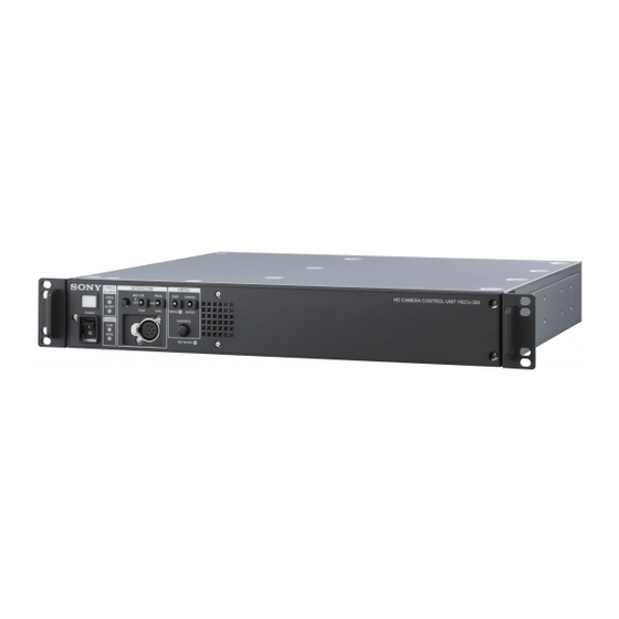
Page 8: Locations And Functions Of Parts
Locations and Functions of Parts Front Panel a Tally light c INTERCOM audio input/output and control block Turns on red to indicate a red tally signal is being received (such as when the picture from the camera connected to the INTERCOM (intercom adjustment) knob CCU is being used). -
Page 9: Rear Panel
d MENU control block e POWER switch Switches the power for the entire system on and off, including the CCU, camera, and the RCP-1000-series Remote Control DISP/MENU (display/menu) lever and indicator Panel connected to the REMOTE connector on the rear panel. CANCEL/ENTER lever Pressing the “?”... - Page 10 i MIC OUT1, MIC OUT2 (microphone output 1, 2) q Pr/R/R-Y, Y/G/Y, Pb/B/B-Y (component signals) connectors (XLR 3-pin) connectors (BNC type) Outputs the camera microphone signals. Outputs the HD component signals, SD component signals, HD RGB signals, or SD RGB signals from the corresponding j CAMERA connector (triax connector) connectors.
-
Page 11: Status Display
Camera settings Status Display Page 1 The CCU system status can be monitored using a picture 1/2 000 O FF monitor connected to the PIX output. For information on monitoring and changing settings, see “Setup Menu” on page 14. Displaying the Status Screen The status screen is controlled using the knob and levers in ND :1 F: 4.7 E X CC: A... - Page 12 Flare: Flare balance R/G/B value TRIAX Type: Triax transmission mode DTL: Detail level TRIAX Cable: CCU triax cable connection status TRIAX Comp.: Triax cable compensation mode selection Note TRIAX Step: Triax cable compensation step (internal circuit The items along the bottom edge are common to both pages 1 and 2. step display) Fan Power: CCU power supply fan status System status...
- Page 13 CCU DPR board diagnostics MacAddress: MAC address stored in CCU EEPROM Auto Negotiation: Auto negotiation setting *DP R Dia g* 10 /12 Auto MDI/MDIX: Auto-MDIX setting Connection Speed: Connection speed setting HD CB :B AR 16 :9( 100 %) Duplex Mode: Communication method setting SD CB :S MPT E SEQ O N:N PN MDI/MDIX: Communications port wiring configuration...
-
Page 14: Setup Menu
To change the displayed page Setup Menu Turn the CONTROL knob to move the , arrow to the page number, then press the CONTROL knob. The , arrow changes to a flashing ? question mark. The CCU system and peripheral settings can be modified Flashing using a picture monitor connected to the PIX output. - Page 15 To change a menu item with multiple input To enter a character string fields Some menu items require a character string input. Moving the , arrow to an item with a character string input Some menus have items with multiple input fields. and pressing the CONTROL knob displays a rectangular Moving the , arrow to an item with multiple input fields and cursor and a list of selectable characters.
-
Page 16: Menu List
Page name Item Settings Menu List Page No. <MULTI FREQUENCY Note FORMAT> Operating frequency selection The following conventions are used in the menu list table. 1.001, 1.000 Settings column values (e.g. ON, OFF, 0): Default settings Note ENTER to execute: Press the CONTROL knob or move the Note CANCEL/ENTER lever to the ENTER position to execute. - Page 17 Page name Item Settings Page name Item Settings Page No. Page No. <OUTPUT SLOT NO <SD ASPECT> SD ASPECT SQUEEZE, EDGE CROP, FORMAT> LETTER BOX SD output aspect 1-1&2 When CAMERA FORMAT selection is 1080/59.94i: SDI OUTPUT 1080/59.94i, 525/59.94i 1/2 connector SD LB SEL 16:9, 15:9, 14:9, 13:9 output format...
- Page 18 Page name Item Settings Page name Item Settings Page No. Page No. <RETURN RET1 When CAMERA FORMAT <RETURN RET4 When CAMERA FORMAT FORMAT> is 1080/59.94i: FORMAT> is 1080/59.94i: Return 1 signal Return 4 signal 1080/59.94i, 525/59.94i, 1080/59.94i, 525/59.94i, format, aspect, format, aspect, NTSC NTSC...
- Page 19 CCU CONFIGURATION menu Page name Item Settings Page No. Page name Item Settings <MONITOR 2> LEVEL GATE ---, 1&2, 1, 2, OFF Page No. ---: Displayed when <COLOR BAR> HD BAR camera not connected, HD output color bar settings video output not set to CAMERA, or video BAR 16:9 (100%), BAR output is set to CAMERA...
- Page 20 Page name Item Settings Page name Item Settings Page No. Page No. <MIC/AUDIO> CAM MIC GAIN (REMOTE), (LOCAL) <FRONT CCU front panel (MIC ON), (OFF), (PGM INCOM> MIC/PGM switch (REMOTE): MIC position (read only) REMOTE source CCU front panel (PRIVATE), (PROD), (LOCAL): Not MIC INTERCOM switch (ENG)
- Page 21 Page name Item Settings Page name Item Settings Page No. Page No. <PROMPTER> MODE NORMAL, LOW LATENCY <VIDEO ADJUST> Video resolution NORMAL: Color picture LEVEL –99 to 99 0 mode switch transmitted as-is in CHROMA –99 to 99 0 standard resolution with delay of approximately 5 frames LEVEL...
- Page 22 NETWORK SETTINGS menu Page name Item Settings Page No. Page name Item Settings <DISPLAY> MESSAGE ALL, WARNING, OFF Page No. ALL: Displays all <TCP/IP IP ADDRESS 0.0.0.0 to 255.255.255.255 messages Camera SETTING> SUBNET MASK 0.0.0.0 to 255.255.255.255 messages and WARNING: Displays switch settings system warning DEFAULT...
- Page 23 Page name Item Settings Page No. <CNS CNS MODE LEGACY, BRIDGE, MCS SETTINGS> Network LEGACY: External connection mode controller connected selection using CCA-5 cable only BRIDGE: External controller connected using point-to-point LAN cable MCS: Multi-camera system configuration of multiple network-capable devices.
-
Page 24: Appendix
• A certain time is required for the video signal transmitted Appendix between the camera and the CCU to stabilize after power is applied. This is not a malfunction. Triax transmission distances (when an HSC-300 is connected) Notes on Use The maximum and minimum transmission distances allowed for triax cable connections are shown in the table below. -
Page 25: Return Signal Combinations
CCU: VIF NG Rear VIF board power supply Specifications error CCU: SY NG Front SY board power supply, HSCU-300 PLD error CCU:RX WARNING Transmission error between General camera and CCU Power supply AC 100 to 240 V, 50/60 Hz Current consumption 4.5 A (max) - Page 26 WF REMOTE D-sub 15-pin, female (1) Always verify that the unit is operating properly before use. (JAE DA-C1-J10 series recommended) SONY WILL NOT BE LIABLE FOR DAMAGES OF ANY WF MODE 4-pin (1) KIND INCLUDING, BUT NOT LIMITED TO, COMPENSATION OR REIMBURSEMENT ON ACCOUNT...
- Page 27 The material contained in this manual consists of information that is the property of Sony Corporation and is intended solely for use by the purchasers of the equipment described in this manual. Sony Corporation expressly prohibits the duplication of any...
- Page 28 Sony Corporation HSCU-300 (UC/CE) 4-140-410-02 (1) © 2009...