
Related Manuals for Sony HDCU3100


Summary of Contents for Sony HDCU3100
- Page 1 4-738-876-11 (1) Camera Control Unit Operating Instructions Before operating the unit, please read this manual thoroughly and retain it for future reference. HDCU3100 © 2018 Sony Corporation...
-
Page 2: Table Of Contents
Table of Contents Overview..............3 System Configuration ............4 Location and Function of Parts....... 5 Front Panel ..............5 Rear Panel ..............6 Status Display ............9 Displaying the Status Screen ..........9 Status Display Screen .............9 Menu Settings ............11 Changing Menu Item Settings ........11 Menu Tree ..............13 Menu List ...............16 Appendix .............. -
Page 3: Overview
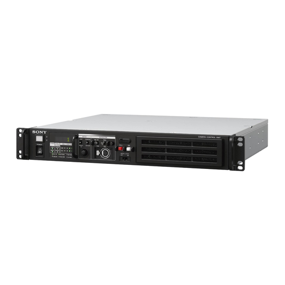
Overview The HDCU3100 Camera Control Unit connects to a Sony HDC2000 Series or HSC300RF/100RF HD Color Camera with an optical fiber cable, and performs signal processing, provides an interface with external equipment, and supplies power to the camera. The unit is equipped with a down-converter for converting HD... -
Page 4: System Configuration
System Configuration Note Production of some of the peripherals and related devices shown in the figures may have been discontinued. For advice on choosing devices, please contact your Sony representative or dealer. Connection example HDVF-EL75/L750/L770 Viewfinder HDVF-200 HDVF-EL20 BKW-401 Viewfinder... -
Page 5: Location And Function Of Parts
Location and Function of Parts Front Panel 4 5 6 a Red tally indicator When the second indicator from the left (yellow) is lit: Reception status is low. Lights in red when this unit receives a red tally signal. You can When the indicator on the left (red) is lit: Reception status attach the supplied number plate here. -
Page 6: Rear Panel
k INTERCOM audio input/output and control block m USB port Used to connect to a USB device. MIC/PGM (microphone/program) switch INTERCOM (intercom select) switch n Assignable button INTERCOM (intercom adjustment) knob You can set a function for this button via the CCU menu. o Filter cover Press the filter cover in the direction of the arrow while pulling it to remove it. - Page 7 Setup Unit. SD composite sync or HD tri-level sync signal generated by the internal sync signal generator will be output from the RET For details on the setup menu, contact a Sony service or sales OUT connector. representative. Refer also to the Master Setup Unit manual.
- Page 8 For details on how to select the signal, contact a Sony service or sales representative. q SDI I/O (3G/HD-SDI input/output) 1/2/3/4 connectors (BNC-type) These can be used as return video inputs, HD prompter inputs, camera video signal outputs, and HD-TRUNK outputs.
-
Page 9: Status Display
a Camera name indication Status Display Displays the name of the connected camera. b Lens file name indication Displays the lens file name. The CCU system status can be monitored using a video monitor connected to the PIX connector. c F drop indication For information on monitoring and changing settings, see Displayed when an F drop occurs. - Page 10 Power Supply: Camera power supply status Camera and unit intercom status Cable Length: Cable length CAM: Camera light sensor level *Intercom* 05/06 CCU: Unit light sensor level Camera Reference: Reference signal format used and genlock status Engineer :MIC On (“Not Detected” is displayed when a reference signal is Producer :MIC Off not input)
-
Page 11: Menu Settings
Menu name Description Menu Settings NETWORK Network-related settings DIAGNOSIS Displays the unit status. The CCU system and peripheral settings can be checked and To select an item in the CCU MENU modified using a video monitor connected to the PIX Turn the CONTROL knob to move the pointer (,) to the connector. - Page 12 Repeat steps 1 to 3 to change other settings on the same page. To enter a character string Some menu items require a character string input. Moving the pointer (,) to an item with a character string input and pressing the CONTROL knob displays a rectangular cursor and a list of selectable characters.
-
Page 13: Menu Tree
Menu Tree SYSTEM CONFIG menu OUTPUT FORMAT2 SDI-I/O1 (S07) MONITOR FORMAT OETF CAMERA I/F CABLE TYPE COLOR (S01) FIBER TRANSMIT RATE SDI-I/O2 OPTICAL SIGNAL MONITOR BARS FORMAT TEST OETF START UP VIDEO SIGNAL COLOR VIDEO I/O SDI-I/O 1 SDI-I/O3 (S02) MONITOR SIGNAL FORMAT... - Page 14 VIDEO/MONITOR menu AUDIO/INTERCOM menu COLOR BAR 4K/HD-BAR SELECT MIC GAIN CAM MIC GAIN (V01) MF-CB (A01) SLOPE AUDIO OUT DELAY SOURCE (A02) AES/EBU OUT SELECT ANALOG OUT BAR-CHARACTER CH1 : LEVEL MOVING SYMBOL CH1 : ADJUST TYPE CH2 : LEVEL SIZE CH2 : ADJUST BAR CHARACTER...
- Page 15 FILE menu CCU FILE FILE INDEX (F01) RECALL STORE EXPORT IMPORT FILE NAME1~5 CLEAR ALL (F02) EXPORT TO USB CLEAR NETWORK menu IP ADDRESS PORT (N01) DHCP IP ADDRESS SUBNET MASK DEFAULT GATEWAY MAC ADDRESS CNS SETTINGS CNS MODE (N02) MCS MODE CCU NO MASTER IP ADDRESS...
-
Page 16: Menu List
Menu List Note The following conventions are used in the menu list table. Settings column values (e.g. ON, OFF, 0): Default settings are underlined Execute via ENTER: Press the CONTROL knob or move the CANCEL/ENTER lever to the ENTER position to execute. SYSTEM CONFIG menu SYSTEM CONFIG Page name... - Page 17 SYSTEM CONFIG Page name Item Set value Description Page No. <REAR I/F> CHARACTER/AES- CHARACTER, AES-EBU Sets the function to assign to the CHARACTER/ AES-EBU connector. CHARACTER: Set to VBS output on which character superposition is performed. AES-EBU: Set to AES-EBU output. PROMPTER2/VBS- ENABLE, DISABLE Sets the function to assign to the PROMPTER2/...
- Page 18 SYSTEM CONFIG Page name Item Set value Description Page No. <MULTI FORMAT> SYSTEM 1.001(525), 1.000(625) Selects the operating frequency of the system. CAMERA FORMAT When 1.001(525) is selected in Selects the format of the system. SYSTEM: 1080/59.94P, 1080/59.94I, 1080/ 29.97PsF, 1080/23.98PsF, 720/ 59.94P, 1080/59.94I (RGB444), 1080/29.97PsF (RGB444), 1080/ 23.98PsF (RGB444), 1080/...
- Page 19 SYSTEM CONFIG Page name Item Set value Description Page No. <OUTPUT FORMAT1> SDI-OUT3 Sets the output for the SDI-OUT 3 connector. MONITOR C, M Sets whether to add characters to the output signal. C: Characters are not added. M: Characters are added. FORMAT See “Formats settable for the SDI Sets the output signal format for the SDI-OUT 3...
- Page 20 SYSTEM CONFIG Page name Item Set value Description Page No. <OUTPUT FORMAT2> SDI-I/O3 Sets the output for the SDI-I/O 3 connector. MONITOR Sets whether to add characters to the output signal. C: Characters are not added. Note This is fixed at C. FORMAT See “Formats settable for the SDI Sets the output signal format for the SDI-I/O 3...
- Page 21 Formats settable for RETURN FORMAT SYSTEM CONFIG t <MULTI HDC2000 series HSC300RF/100RF FORMAT> page t SYSTEM (When SYSTEM CONFIG t <CAMERA I/F> t (When SYSTEM CONFIG t <CAMERA I/F> t settings FIBER TRANSMIT RATE is set to HIGH) FIBER TRANSMIT RATE is set to HD) 1001 1080/59.94P 1080/59.94I...
- Page 22 SYSTEM CONFIG t <MULTI HDC2000 series HSC300RF/100RF FORMAT> page t CAMERA (When SYSTEM CONFIG t <CAMERA I/F> t (When SYSTEM CONFIG t <CAMERA I/F> t FORMAT settings FIBER TRANSMIT RATE is set to HIGH) FIBER TRANSMIT RATE is set to HD) 1080/59.94I(2x) 1080/59.94I (2x)/3G-B –...
- Page 23 VIDEO/MONITOR menu VIDEO/MONITOR Page name Item Set value Description Page No. <COLOR BAR> 4K/HD-BAR SELECT BAR 16:9(100%), BAR 16:9(75%), Selects the color bar of 4K output/HD output. SMPTE 16:9(BLACK), SMPTE 16:9(-I/Q), BAR 4:3(100%), BAR 4:3(75%), SMPTE 4:3(BLACK), SMPTE 4:3(-I/Q), MF-ARIB(75%), MF-ARIB(100%), MF-ARIB(+I), MF- SMPTE(-I,Q), MF-SMPTE(75%,Q), MF-SMPTE(100%,Q), MF-...
- Page 24 VIDEO/MONITOR Page name Item Set value Description Page No. <MONITOR> CHARACTER LEVEL 1, 2, 3, 4, 5 Sets the brightness of text in menus, etc. LEVEL GATE OFF, 1&2, 1, 2, (---) Sets level gate display. OFF: Level gate is not displayed. 1: Displays level gate 1.
- Page 25 VIDEO/MONITOR Page name Item Set value Description Page No. <DISPLAY> MESSAGE ALL, WARNING, OFF Sets the display of messages for the camera auto setup operation status, warnings that occur in the system, etc. Sets the items to be ALL: Displays all messages. displayed on the camera setting status page of the WARNING: Displays system warning messages and...
- Page 26 AUDIO/INTERCOM Page name Item Set value Description Page No. <INTERCOM> INTERCOM CH 1CH(PROD), 2CH(PROD&ENG) Selects the intercom channel number to be used. PRODUCER CLEAR COM, 4WIRE, RTS Sets the producer line intercom system. INTERFACE SIDETONE –99 to 99 0 Sets the side tone cancel level. (Setting is possible CANCEL when CLEAR COM or RTS) TERMINATION...
- Page 27 MAINTENANCE menu MAINTENANCE Page name Item Set value Description Page No. <TRUNK/PROMPTER> TRUNK LINE CHANNEL MODE When FIBER TRANSMIT RATE is Sets the number of channels to be used. set to HIGH: 2CH(MAX 75Kbps), 1CH(MAX 150Kbps) When FIBER TRANSMIT RATE is set to HD: 1CH(MAX 38Kbps) INTERFACE 232C, 422A...
- Page 28 Saves the CCU file to the internal memory. EXPORT Exports the CCU file to the USB flash drive. The path for the USB flash drive is “/MSSONY/PRO/ CAMERA/HDCU3100.” IMPORT Imports the CCU file from the USB flash drive. The path for the USB flash drive is “/MSSONY/PRO/ CAMERA/HDCU3100.”...
- Page 29 Enables or disables saving of log files. EXPORT TO USB Saves logs to the USB flash drive. (Execute via EXEC.) The path for the USB flash drive is “/MSSONY/PRO/ CAMERA/HDCU3100.” CLEAR Deletes logs stored internally on the unit. (Execute via EXEC.) Note Logs for up to 30 days are stored.
- Page 30 DIAGNOSIS menu DIAGNOSIS Page name Item Display Description Page No. <BOARD STATUS> OK, POWER ERROR, PLD VIF board self-diagnosis result ERROR, TEMP WARNING POWER ON HOUR 99999 H Accumulated power-on time from power on. METER HOUR METER 99999 H Accumulated power-on time <SERIAL NUMBER>...
-
Page 31: Appendix
CCU:OPTICAL CONDITION the life expectancy of these parts is guaranteed. For details on ERROR parts replacement, contact your Sony representative. CCU:PS FAN STOP Power supply block FAN error The life expectancy of the electrolytic capacitor is about... -
Page 32: Specifications
REFERENCE IN/OUT BNC-type (2), loop-through output Specifications HD: SMPTE ST274, tri-level sync, 0.6 Vp- p, 75 ohms SD: Black burst (NTSC: 0.286 Vp-p, 75 ohms/PAL: 0.3 Vp-p, 75 ohms) or NTSC 10F-BB General Input connectors Power requirements 100 V to 240 V AC, 50/60 Hz AC IN 100 V to 240 V AC (1) Current consumption... - Page 33 On the basis of license contracts between Sony and the software copyright holders, this product uses open software. To meet the requirements of the software copyright holders, Sony is obligated to inform you of the content of these licenses. For the content of these licenses, see “License1.pdf” in the “License”...