HP ProLiant DL380 User Manual
Generation 5 server
Hide thumbs
Also See for ProLiant DL380:
- User manual (164 pages) ,
- Maintenance and service manual (104 pages) ,
- Quickspecs (60 pages)

Related Manuals for HP ProLiant DL380


Summary of Contents for HP ProLiant DL380
-
Page 1: User Guide
HP ProLiant DL380 Generation 5 Server User Guide Part Number 403166-004 January 2007 (Fourth Edition) - Page 2 The information contained herein is subject to change without notice. The only warranties for HP products and services are set forth in the express warranty statements accompanying such products and services. Nothing herein should be construed as constituting an additional warranty. HP shall not be liable for technical or editorial errors or omissions contained herein.
-
Page 3: Table Of Contents
Optimum environment... 29 Space and airflow requirements ... 29 Temperature requirements... 30 Power requirements ... 30 Electrical grounding requirements ... 31 Rack warnings ... 31 Identifying the contents of the server shipping carton... 31 Installing hardware options... 32 Contents 3... - Page 4 PCI riser board option... 55 Cabling ... 57 SAS hard drive cabling ... 57 PCI SAS cabling to an HP Smart Array P400i Controller... 57 PCI SAS cabling to optional expansion board controller ... 58 Fan board cabling... 58 Hard drive backplane power cabling... 59 Media drive bay cabling...
- Page 5 Survey Utility... 68 Integrated Management Log ... 68 Array Diagnostic Utility ... 69 Remote support and analysis tools ... 69 HP Instant Support Enterprise Edition... 69 Web-Based Enterprise Service... 69 Open Services Event Manager ... 69 Keeping the system current ... 69 Drivers ...
- Page 6 Grounding methods to prevent electrostatic discharge ... 95 Specifications ... 96 Environmental specifications ... 96 Server specifications ... 96 Technical support... 98 Before you contact HP... 98 HP contact information ... 98 Customer Self Repair ... 98 Acronyms and abbreviations... 106 Index... 110...
-
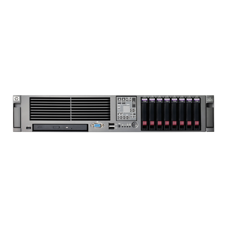
Page 7: Component Identification
Component identification In this section Front panel components ... 7 Front panel LEDs and buttons ... 8 Systems Insight Display LEDs... 9 Rear panel components... 10 Rear panel LEDs and buttons ... 11 System board... 12 Systems Insight Display LEDs and internal health LED combinations ... 15 SAS device numbers... -
Page 8: Front Panel Leds And Buttons
Front panel LEDs and buttons Item Description UID LED button Internal health LED External health LED (power supply) NIC 1 link/activity LED NIC 2 link/activity LED Power On/Standby button/system power LED Status Blue = Activated Flashing = System being remotely managed Off = Deactivated Green = Normal Amber = System degraded. -
Page 9: Systems Insight Display Leds
Test each bank of FBDIMMs by removing all other FBDIMMs. Isolate the failed FBDIMM by replacing each FBDIMM in a bank with a known working FBDIMM. NOTE: The HP Systems Insight Display LEDs represent the system board layout. Status Off = No protection... -
Page 10: Rear Panel Components
Rear panel components Item Description Expansion slot 1 Expansion slot 2 Expansion slot 3 Expansion slot 4 Expansion slot 5 T-10/T-15 Torx screwdriver External option blank NIC 2 connector NIC 1 connector Power supply bay 2 Power cord connector Power supply bay 1 (populated) iLO 2 connector Video connector USB connectors (2) -
Page 11: Rear Panel Leds And Buttons
Item PCIe x8, slot 4, bus D x8, slot 5, bus E x4 slots: x8 cards are supported, but will run at x4 speeds. x8 slots: x16 cards are supported, but will run at x8 speeds. All slots are non-hot-plug. Rear panel LEDs and buttons Item Description... -
Page 12: System Board
System board System board components (6-fan configuration) Item Description Fan board connector PPM 1 PPM 2 Power supply backplane connector PCIe slot 1 PCIe slot 2 NMI jumper iLO 2 diagnostic LEDs System maintenance switch Internal USB connector* System battery PCI riser cage connector Fan 2 connector Fan 1 connector... -
Page 13: System Board Components (12-Fan Configuration)
System board components (12-fan configuration) Item Description Fan board connector PPM 1 PPM 2 Power supply backplane connector PCIe slot 1 PCIe slot 2 NMI jumper iLO 2 diagnostic LEDs System maintenance switch Internal USB connector* System battery PCI riser cage connector Fan 4 connector Fan 2 connector Fan 3 connector... -
Page 14: System Maintenance Switch
Short the NMI jumper pins Press the NMI switch Use the iLO Virtual NMI feature For additional information, see the whitepaper on the HP website (http://h20000.www2.hp.com/bc/docs/support/SupportManual/c00797875/c00797875.pdf). Function Off = iLO 2 security is enabled. On = iLO 2 security is disabled. -
Page 15: Fbdimm Slots
Systems Insight Display LEDs and internal health LED combinations When the internal health LED on the front panel illuminates either amber or red, the server is experiencing a health event. Combinations of illuminated system LEDs and the internal health LED indicate system status. -
Page 16: Sas Device Numbers
Green Mirrored memory enabled and not failed. Amber The Health Driver has detected a cautionary temperature level. The server has detected a hardware critical temperature level. PCI riser cage is not seated. Amber One fan is failed or removed. Two or more fans have failed or are removed. -
Page 17: Sas And Sata Hard Drive Leds
SAS and SATA hard drive LEDs Item Description Fault/UID LED (amber/blue) Online LED (green) SAS and SATA hard drive LED combinations Online/activity Fault/UID LED LED (green) (amber/blue) On, off, or Alternating amber and flashing blue On, off, or Steadily blue flashing Amber, flashing regularly (1 Hz) -
Page 18: Pci Riser Cage Led
(1 Hz) PCI riser cage LED CAUTION: To prevent damage to the server or expansion boards, power down the server and remove all AC power cords before removing or installing the PCI riser cage. Status On = AC power connected... -
Page 19: Battery Pack Leds
The battery lifetime also depends on the cache module size. For further information, refer to the controller QuickSpecs on the HP website (http://www.hp.com). The cache microcontroller is waiting for the host controller to communicate. -
Page 20: Hot-Plug Fans (6-Fan Configuration)
LED3 pattern LED4 pattern — One blink per second — Steady glow — One blink per One blink per second second Steady glow — One blink per — second Hot-plug fans (6-fan configuration) Interpretation The battery pack is below the minimum charge level and is being charged. -
Page 21: Hot-Plug Fans (12-Fan Configuration)
Hot-plug fans (12-fan configuration) Fan board components Item Description Fan connectors (8)* Systems Insight Display connector Power On/Standby button/system power LED UID LED button USB connectors (2) Video connector Fan board system connector *Only the 12-fan configuration supports all connectors. Component identification 21... -
Page 22: Operations
If the operating system automatically places the server in Standby mode, omit the next step. Press the Power On/Standby button to place the server in Standby mode. When the server activates Standby power mode, the system power LED changes to amber. -
Page 23: Remove The Access Panel
Press the server rail-release latches and slide the server fully into rack. WARNING: release latches and sliding the server into the rack. The sliding rails could pinch your fingers. Press the server firmly into the rack to secure it in place. -
Page 24: Install The Access Panel
Lift up on the hood latch handle and remove the access panel. Install the access panel Place the access panel on top of the server with the hood latch open. Allow the panel to extend past the rear of the server approximately 1.25 cm (0.5 in). -
Page 25: Install The Pci Riser Cage
Install the PCI riser cage CAUTION: To prevent damage to the server or expansion boards, power down the server and remove all AC power cords before removing or installing the PCI riser cage. Align the PCI riser cage with the chassis and slide it into place. -
Page 26: Access The Product Rear Panel
Power up the server (on page 22). Access the product rear panel Cable management arm with left-hand swing To access the server rear panel, open the cable management arm. Cable management arm with right-hand swing NOTE: To access some components, you may need to remove the cable management arm. -
Page 27: Hot-Plug Fan Operation
The server shuts down in the following scenarios: At POST: The BIOS suspends the server for 5 minutes if it detects a cautionary temperature level. If the cautionary temperature level is still detected after 5 minutes, the BIOS performs an orderly shutdown and enters Standby mode. -
Page 28: Setup
Registering the server... 35 Optional installation services Delivered by experienced, certified engineers, HP Care Pack services help you keep your servers up and running with support packages tailored specifically for HP ProLiant systems. HP Care Packs let you integrate both hardware and software support into a single package. A number of service level options are available to meet your needs. -
Page 29: Rack Planning Resources
HP servers draw in cool air through the front door and expel warm air through the rear door. Therefore, the front and rear rack doors must be adequately ventilated to allow ambient room air to enter the cabinet, and the rear door must be adequately ventilated to allow the warm air to escape from the cabinet. -
Page 30: Temperature Requirements
Do not use common power outlet strips for this equipment. Provide a separate electrical circuit for the server. The HP ProLiant DL380 Generation 5 Server cable management arm is not To reduce the risk of personal injury, fire, or damage to the equipment, do not... -
Page 31: Electrical Grounding Requirements
Because of the high ground-leakage currents associated with multiple servers connected to the same power source, HP recommends the use of a PDU that is either permanently wired to the building’s branch circuit or includes a nondetachable cord that is wired to an industrial-style plug. NEMA locking-style plugs or those complying with IEC 60309 are considered suitable for this purpose. -
Page 32: Installing Hardware Options
Install the heaviest item first, and continue to populate the rack from the bottom to the top. Install the server and cable management arm into the rack. For more information, refer to the installation instructions that ship with the 2U Quick Deploy Rail System. - Page 33 Secure cables to the cable management arm. IMPORTANT: When using cable management arm components, be sure to leave enough slack in each of the cables to prevent damage to the cables when the server is extended from the rack. —...
-
Page 34: Installing The Operating System
This process may require you to obtain additional drivers from the HP website (http://www.hp.com/support). For information on using these installation paths, refer to the SmartStart installation poster in the HP ProLiant Essentials Foundation Pack, included with the server. Powering up and configuring the server To power up the server, press the Power On/Standby button. -
Page 35: Registering The Server
Press the F9 key when prompted during the boot process to change the server settings using RBSU. The system is set up by default for the English language. For more information on the automatic configuration, refer to the HP ROM-Based Setup Utility User Guide located on the Documentation CD. -
Page 36: Hardware Options Installation
2 and provide a processor failure message. The server uses PPMs to provide power to each processor. The corresponding PPM must be installed for each processor or the system cannot boot. - Page 37 IMPORTANT: Processor socket 1 and PPM slot 1 must be populated at all times or the server does not function properly. IMPORTANT: Always install a PPM when you install a processor. The system fails to boot if the corresponding PPM is missing.
- Page 38 Open the processor retaining latch and the processor socket retaining bracket. Remove the processor socket protective cover. IMPORTANT: Be sure the processor remains inside the processor installation tool. Hardware options installation 38...
- Page 39 If the processor has separated from the installation tool, carefully re-insert the processor in the tool. Align the processor installation tool with the socket and install the processor. Hardware options installation 39...
- Page 40 Close the processor socket retaining bracket and the processor retaining latch. CAUTION: To prevent possible server malfunction or damage to the equipment, be sure to completely close the processor locking lever. Remove the heatsink cover.
- Page 41 Install the heatsink. Hardware options installation 41...
- Page 42 Close the heatsink retaining bracket. Open the latches on the corresponding PPM slot. Install the PPM. Hardware options installation 42...
-
Page 43: Memory Options
The Advanced Memory Protection option is configured in RBSU. By default, the server is set to Advanced ECC mode. For more information, refer to HP ROM-Based Setup Utility (on page 62). If the configured AMP mode is not supported by the installed FBDIMM configuration, the system boots in Advanced ECC mode. -
Page 44: Advanced Ecc Memory
FBDIMMS must be ECC Registered DDR-2 SDRAM FBDIMMs. FBDIMMs must be installed in pairs. FBDIMM pairs in a memory bank must have identical HP part numbers. FBDIMMS must be populated as specified for each AMP memory mode. The memory subsystem for this server is divided into two branches. Each memory branch is essentially a separate memory controller. -
Page 45: Mirrored Memory Configuration
If one of the non-spare FBDIMMs receives correctable memory errors at a higher rate than a specific threshold, the server automatically copies the memory contents of the degraded rank to the online spare rank. The server then deactivates the failing rank and automatically switches over to the online spare. -
Page 46: Installing Fbdimms
CAUTION: To avoid damage to the hard drives, memory, and other system components, the air baffle, drive blanks, and access panel must be installed when the server is powered up. Power down the server (on page 22). Extend the server from the rack (on page 22). -
Page 47: Hot-Plug Sas Hard Drive Options
LED combinations (on page 15)." Hot-plug SAS hard drive options When adding hard drives to the server, observe the following general guidelines: The system automatically sets all device numbers. If only one hard drive is used, install it in the bay with the lowest device number numbers"... -
Page 48: Removing A Hot-Plug Sas Hard Drive
Removing a hot-plug SAS hard drive CAUTION: To prevent improper cooling and thermal damage, do not operate the server unless all bays are populated with either a component or a blank. Determine the status of the hard drive from the hot-plug SAS hard drive LED combinations SATA hard drive LED Back up all server data on the hard drive. -
Page 49: Redundant Hot-Plug Ac Power Supply Option
Slide the CD/DVD-ROM drive or diskette drive into the drive bay. Redundant hot-plug AC power supply option CAUTION: To prevent improper cooling and thermal damage, do not operate the server unless all bays are populated with either a component or a blank. Access the product rear panel (on page 26). -
Page 50: Dc Power Supply Option
Slide the power supply into the power supply bay. Connect the power cord to the power supply. Route the power cord through the power cord anchor or cable management arm. Reposition the cable management arm into the operating position. Connect the power cord to the power source. Be sure that the power supply LED is green Be sure that the front panel external health LED is green DC power supply option... - Page 51 To reduce the risk of electric shock, fire, and damage to the equipment, this product must be installed in accordance with the following guidelines: This power supply is intended only for installation in HP servers located in a restricted access location.
- Page 52 Remove the power supply blank. WARNING: To reduce the risk of electric shock or damage to the equipment, do not connect the power cord to the power supply until the power supply is installed. Slide the power supply into the power supply bay until the release/lock lever clicks, securing the power supply.
-
Page 53: Expansion Board Options
Install the access panel (on page 24). Removing expansion slot covers (slots 3, 4, and 5) CAUTION: To prevent damage to the server or expansion boards, power down the server and remove all AC power cords before removing or installing the PCI riser cage. CAUTION: To prevent improper cooling and thermal damage, do not operate the server unless all PCI slots have either an expansion slot cover or an expansion board installed. -
Page 54: Installing An Expansion Board (Slot 3, 4, Or 5)
Installing an expansion board (slot 3, 4, or 5) CAUTION: To prevent damage to the server or expansion boards, power down the server and remove all AC power cords before removing or installing the PCI riser cage. Power down the server (on page 22). -
Page 55: Pci Riser Board Option
PCI riser board option To install the component: CAUTION: To prevent improper cooling and thermal damage, do not operate the server unless all PCI slots have either an expansion slot cover or an expansion board installed. Power down the server (on page 22). - Page 56 Install any expansion boards. Install the PCI riser cage (on page 25). Install the access panel (on page 24). Install the server into the rack. Power up the server (on page 22). ("Expansion board options" on page 53) Hardware options installation 56...
-
Page 57: Cabling
Fan board cabling... 58 Hard drive backplane power cabling ... 59 Media drive bay cabling... 59 Battery cabling for BBWC ... 60 Systems Insight Display cabling... 60 SAS hard drive cabling PCI SAS cabling to an HP Smart Array P400i Controller Cabling 57... -
Page 58: Pci Sas Cabling To Optional Expansion Board Controller
PCI SAS cabling to optional expansion board controller Fan board cabling Cabling 58... -
Page 59: Hard Drive Backplane Power Cabling
Hard drive backplane power cabling Media drive bay cabling Cabling 59... -
Page 60: Battery Cabling For Bbwc
Battery cabling for BBWC NOTE: Use the retaining clip to manage excess cable slack. Systems Insight Display cabling Cabling 60... -
Page 61: Configuration And Utilities
This automated server configuration process cuts time from each server deployed, making it possible to scale server deployments to high volumes in a rapid manner. For more information, and to download the SmartStart Scripting Toolkit, refer to the HP website (http://www.hp.com/servers/sstoolkit). -
Page 62: Hp Rom-Based Setup Utility
Selecting the primary boot controller Configuring memory options Language selection For more information on RBSU, refer to the HP ROM-Based Setup Utility User Guide on the Documentation CD or the HP website (http://www.hp.com/servers/smartstart). Using RBSU The first time you power up the server, the system prompts you to enter RBSU and select a language. -
Page 63: Boot Options
RBSU by pressing the F9 key when prompted. After the settings are selected, exit RBSU and allow the server to reboot automatically. For more information, refer to the HP ROM-Based Setup Utility User Guide on the Documentation CD or the HP website (http://www.hp.com/servers/smartstart). -
Page 64: Array Configuration Utility
Servers running Microsoft® operating systems require Internet Explorer 5.5 (with Service Pack 1) or later. For Linux servers, refer to the README.TXT file for additional browser and support information. For more information, refer to the Configuring Arrays on HP Smart Array Controllers Reference Guide on the Documentation CD or the HP website (http://www.hp.com). -
Page 65: Re-Entering The Server Serial Number And Product Id
ASR increases server availability by restarting the server within a specified time after a system hang or shutdown. At the same time, the HP SIM console notifies you by sending a message to a designated pager number that ASR has restarted the system. You can disable ASR from the HP SIM console or through RBSU. -
Page 66: Integrated Lights-Out 2 Technology
IMPORTANT: processors, SAS and SCSI hard drives, and memory modules. For additional information, refer to the Management CD in the HP ProLiant Essentials Foundation Pack or the HP SIM website (http://www.hp.com/go/hpsim). You must install and use HP SIM to benefit from the Pre-Failure Warranty for ("SmartStart... -
Page 67: Management Agents
ROM. USB support HP provides both standard USB support and legacy USB support. Standard support is provided by the operating system through the appropriate USB device drivers. HP provides support for USB devices prior to the operating system loading through legacy USB support, which is enabled by default in the system ROM. -
Page 68: Diagnostic Tools
If a significant change occurs between data-gathering intervals, the Survey Utility marks the previous information and overwrites the Survey text files to reflect the latest changes in the configuration. Survey Utility is installed with every SmartStart-assisted installation or can be installed through the HP PSP ("ProLiant Support Packs"... -
Page 69: Array Diagnostic Utility
For more information, refer to the Management CD in the HP ProLiant Essentials Foundation Pack. Array Diagnostic Utility The HP Array Diagnostics Utility is a web-based application that creates a report of all HP storage controllers and disk drives. This report provides vital information to assist in identifying faults or conditions that may require attention. -
Page 70: Proliant Support Packs
(http://h18000.www1.hp.com/support/files/index.html). Change control and proactive notification HP offers Change Control and Proactive Notification to notify customers 30 to 60 days in advance of upcoming hardware and software changes on HP commercial products. For more information, refer to the HP website (http://www.hp.com/go/pcn). -
Page 71: Care Pack
Care Pack HP Care Pack Services offer upgraded service levels to extend and expand standard product warranty with easy-to-buy, easy-to-use support packages that help you make the most of your server investments. Refer to the Care Pack website (http://www.hp.com/hps/carepack/servers/cp_proliant.html). Configuration and utilities 71... -
Page 72: Troubleshooting
To obtain the guide, refer to any of the following sources and then select the HP ProLiant Servers Troubleshooting Guide: The server-specific Documentation CD The Business Support Center on the HP website (http://www.hp.com/support). -
Page 73: Symbols On Equipment
To reduce the risk of electric shock, fire, or damage to the equipment, To reduce the risk of injury from a hot component, allow the surface to To reduce the risk of personal injury or damage to the equipment, Only authorized technicians trained by HP should attempt to repair this Troubleshooting 73... -
Page 74: Symptom Information
47.18 - 60 lb The server is unstable when not fastened to the rails. When mounting the server in a rack, remove the power supplies and any other CAUTION: To properly ventilate the system, you must provide at least 7.6 cm (3.0 in) of clearance at the front and back of the server. -
Page 75: Prepare The Server For Diagnosis
Run HP Insight Diagnostics (on page 68) and use the survey page to view the current configuration or to compare it to previous configurations. Refer to your hardware and software records for information. Refer to server LEDs and their statuses. -
Page 76: Service Notifications
Select the appropriate server model, and then click the Troubleshoot a Problem link on the product page. Troubleshooting flowcharts To effectively troubleshoot a problem, HP recommends that you start with the first flowchart in this section, "Start diagnosis flowchart (on page 76)," and follow the appropriate diagnostic path. If the other flowcharts do not provide a troubleshooting solution, follow the diagnostic steps in "General diagnosis... -
Page 77: General Diagnosis Flowchart
General diagnosis flowchart The General diagnosis flowchart provides a generic approach to troubleshooting. If you are unsure of the problem, or if the other flowcharts do not fix the problem, use the following flowchart. Item Refer to "Symptom information (on page 74)" "Loose connections (on page 75)"... - Page 78 HP ROM-BIOS/Firmware Updates website (http://h18023.www1.hp.com/support/files/server/us/romflash.ht "General memory problems are occurring" in the HP ProLiant Servers Troubleshooting Guide located on the Documentation CD or on the HP website (http://www.hp.com/support) Server maintenance and service guide, located on the Documentation CD or the HP website (http://www.hp.com/products/servers/platforms)
-
Page 79: Server Power-On Problems Flowchart
Server power-on problems flowchart Symptoms: The server does not power on. The system power LED is off or amber. The external health LED is red or amber. Troubleshooting 79... - Page 80 Faulty internal component Item Refer to "Component identification (on page 7)" "HP Insight Diagnostics (on page 68)" or in the HP ProLiant Servers Troubleshooting Guide located on the Documentation CD or on the HP website (http://www.hp.com/support) "Loose connections (on page 75)"...
- Page 81 Troubleshooting 81...
-
Page 82: Post Problems Flowchart
"Symptom information (on page 74)" Server maintenance and service guide, located on the Documentation CD or the HP website (http://www.hp.com/products/servers/platforms) "Port 85 and iLO messages" in the HP ProLiant Servers Troubleshooting Guide located on the Documentation CD or on the HP website (http://www.hp.com/support) "General memory problems are occurring"... -
Page 83: Os Boot Problems Flowchart
OS boot problems flowchart Symptoms: Server does not boot a previously installed operating system Server does not boot SmartStart Possible causes: Corrupted operating system Hard drive subsystem problem Incorrect boot order setting in RBSU Troubleshooting 83... - Page 84 Guide located on the Documentation CD or on the HP website (http://www.hp.com/support) Controller documentation "HP Insight Diagnostics (on page 68)" or in the HP ProLiant Servers Troubleshooting Guide located on the Documentation CD or on the HP website (http://www.hp.com/support) "CD-ROM and DVD drive problems" in the HP ProLiant Servers Troubleshooting Guide located on the Documentation CD or on the HP website (http://www.hp.com/support)
-
Page 85: Server Fault Indications Flowchart
Server fault indications flowchart Symptoms: Server boots, but a fault event is reported by Insight Management Agents (on page 67) Server boots, but the internal health LED, external health LED, or component health LED is red or amber NOTE: For the location of server LEDs and information on their statuses, refer to the server documentation. - Page 86 CD or the HP website (http://www.hp.com/products/servers/platforms) "HP contact information (on page 98)" "HP Insight Diagnostics (on page 68)" or in the HP ProLiant Servers Troubleshooting Guide located on the Documentation CD or on the HP website (http://www.hp.com/support) "Hardware problems" in the HP ProLiant Servers Troubleshooting Guide located on the Documentation CD or on the HP website (http://www.hp.com/support)
-
Page 87: Post Error Messages And Beep Codes
POST error messages and beep codes For a complete listing of error messages, refer to the "POST error messages" in the HP ProLiant Servers Troubleshooting Guide located on the Documentation CD or on the HP website (http://www.hp.com/support). WARNING: information in the server documentation before removing, replacing, reseating, or modifying... -
Page 88: System Battery
System battery If the server no longer automatically displays the correct date and time, you may need to replace the battery that provides power to the real-time clock. Under normal use, battery life could be 5 to 10 years. WARNING: pentoxide, or an alkaline battery pack. -
Page 89: Regulatory Compliance Notices
Regulatory compliance notices In this section Regulatory compliance identification numbers ... 89 Federal Communications Commission notice ... 89 Declaration of conformity for products marked with the FCC logo, United States only... 90 Modifications... 91 Cables ... 91 Canadian notice (Avis Canadien) ... 91 European Union regulatory notice ... -
Page 90: Class A Equipment
For questions regarding this product, contact us by mail or telephone: Hewlett-Packard Company P. O. Box 692000, Mail Stop 530113 Houston, Texas 77269-2000 1-800-HP-INVENT (1-800-474-6836). (For continuous quality improvement, calls may be recorded or monitored.) For questions regarding this FCC declaration, contact us by mail or telephone: Hewlett-Packard Company P. -
Page 91: Modifications
Modifications The FCC requires the user to be notified that any changes or modifications made to this device that are not expressly approved by Hewlett-Packard Company may void the user’s authority to operate the equipment. Cables Connections to this device must be made with shielded cables with metallic RFI/EMI connector hoods in order to maintain compliance with FCC Rules and Regulations. -
Page 92: Disposal Of Waste Equipment By Users In Private Households In The European Union
Disposal of waste equipment by users in private households in the European Union This symbol on the product or on its packaging indicates that this product must not be disposed of with your other household waste. Instead, it is your responsibility to dispose of your waste equipment by handing it over to a designated collection point for the recycling of waste electrical and electronic equipment. -
Page 93: Korean Notice
Do not operate controls, make adjustments, or perform procedures to the laser device other than those specified herein. Allow only HP Authorized Service technicians to repair the unit. The Center for Devices and Radiological Health (CDRH) of the U.S. Food and Drug Administration implemented regulations for laser products on August 2, 1976. -
Page 94: Taiwan Battery Recycling Notice
To forward them to recycling or proper disposal, please use the public collection system or return them to HP, an authorized HP Partner, or their agents. For more information about battery replacement or proper disposal, contact an authorized reseller or an authorized service provider. -
Page 95: Electrostatic Discharge
Electrostatic discharge In this section Preventing electrostatic discharge... 95 Grounding methods to prevent electrostatic discharge ... 95 Preventing electrostatic discharge To prevent damaging the system, be aware of the precautions you need to follow when setting up the system or handling parts. A discharge of static electricity from a finger or other conductor may damage system boards or other static-sensitive devices. -
Page 96: Specifications
Specifications In this section Environmental specifications ... 96 Server specifications ... 96 Environmental specifications Specification Temperature range* Operating Shipping Storage Maximum wet bulb temperature Relative humidity (noncondensing)** Operating Non-operating * All temperature ratings shown are for sea level. An altitude derating of 1°C per 300 m (1.8°F per 1,000 ft) to 3048 m (10,000 ft) is applicable. - Page 97 Rated input power 980 W at 100V AC input 960 W at 200V AC input BTUs per hour 3344 at 100V to 120V AC input 3277 at 200V to 240V AC input Power supply output Rated steady-state power 800 W at 100V AC input 850 W at 120V AC input 1000 W at 200V to 240V AC input...
-
Page 98: Technical Support
CSR part, HP will ship that part directly to you for replacement. There are two categories of CSR parts: Mandatory—Parts for which customer self repair is mandatory. If you request HP to replace these parts, you will be charged for the travel and labor costs of this service. - Page 99 HP specifies in the materials shipped with a replacement CSR part whether a defective part must be returned to HP. In cases where it is required to return the defective part to HP, you must ship the defective part back to HP within a defined period of time, normally five (5) business days.
- Page 100 La mancata restituzione del componente può comportare la fatturazione del ricambio da parte di HP. Nel caso di riparazione da parte del cliente, HP sostiene tutte le spese di spedizione e resa e sceglie il corriere/vettore da utilizzare.
- Page 101 Si no enviara el componente defectuoso requerido, HP podrá cobrarle por el de sustitución. En el caso de todas sustituciones que lleve a cabo el cliente, HP se hará cargo de todos los gastos de envío y devolución de componentes y escogerá la empresa de transporte que se utilice para dicho servicio.
- Page 102 Opcional – Peças cujo reparo feito pelo cliente é opcional. Essas peças também são projetadas para o reparo feito pelo cliente. No entanto, se desejar que a HP as substitua, pode haver ou não a cobrança de taxa adicional, dependendo do tipo de serviço de garantia destinado ao produto.
- Page 103 HP paga todas as despesas de transporte e de devolução da peça e determina a transportadora/serviço postal a ser utilizado. Para obter mais informações sobre o programa de reparo feito pelo cliente da HP, entre em contato com o fornecedor de serviços local.
- Page 104 Technical support 104...
- Page 105 Technical support 105...
-
Page 106: Acronyms And Abbreviations
Acronyms and abbreviations ABEND abnormal end Array Configuration Utility Advanced Memory Protection Automatic Server Recovery BBWC battery-backed write cache BIOS Basic Input/Output System Canadian Standards Association Customer Self Repair double data rate DIMM dual inline memory module error checking and correcting... - Page 107 HTTP hypertext transfer protocol integrated device electronics International Electrotechnical Commission Integrated Lights-Out Integrated Management Log ISEE Instant Support Enterprise Edition light-emitting diode NFPA National Fire Protection Association network interface controller non-maskable interrupt NVRAM non-volatile memory ORCA Option ROM Configuration for Arrays operating system peripheral component interface Acronyms and abbreviations 107...
- Page 108 PCI Express Peripheral Component Interconnect Express PCI-X peripheral component interconnect extended PCIe peripheral component interconnect express POST Power-On Self Test processor power module ProLiant Support Pack RBSU ROM-Based Setup Utility Rapid Deployment Pack read-only memory serial attached SCSI SDRAM synchronous dynamic RAM small form-factor Systems Insight Manager SMTP...
- Page 109 SNMP Simple Network Management Protocol TMRA recommended ambient operating temperature unit identification uninterruptible power system universal serial bus Version Control Agent Acronyms and abbreviations 109...
-
Page 110: Index
7 configuration of system 35, 63 Configuration Replication Utility 64 configuration tools 63 connection problems 77 connectors 7 contacting HP 100 creating a disk image 67 DC power supply 52 Declaration of Conformity 92 deployment software 67 device numbers 16... - Page 111 37 hot-plug fans 27 HP Insight Diagnostics 70 HP ProLiant Essentials Foundation Pack 69 HP ProLiant Essentials Rapid Deployment Pack 67 HP Systems Insight Manager, overview 69 identification number 91 iLO (Integrated Lights-Out) 68 iLO 2 activity LED 11...
- Page 112 SATA hard drive LEDs 17 scripted installation 63 serial connector 10, 59 serial number 67 series number 91 server features and options 37 server, installation 33 service notifications 78 shipping carton contents 32 SmartStart autorun menu 63 SmartStart Scripting Toolkit 63...
- Page 113 Taiwan battery recycling notice 96 technical support 100 telephone numbers 100 temperature requirements 31 Torx screwdriver 10 troubleshooting 74 UID LEDs 7, 8, 11 updating the system ROM 69 USB connectors 7, 10 USB support 70 utilities 63 utilities, deployment 63, 64, 67 ventilation 30 video connector 7, 10 warnings 32, 75...