Motorola MC9190-G User Manual
Mobile computer
Hide thumbs
Also See for MC9190-G:
- Integrator manual (190 pages) ,
- Application manual (28 pages) ,
- Quick start manual (2 pages)
Table of Contents
Advertisement
Advertisement
Table of Contents
Troubleshooting

Related Manuals for Motorola MC9190-G


Summary of Contents for Motorola MC9190-G
- Page 1 MC9190-G User Guide...
-
Page 3: User Guide
MC9190-G User Guide 72E-140936-01 Rev A January 2011... - Page 4 Motorola. No right to copy a licensed program in whole or in part is granted, except as permitted under copyright law. The user shall not modify, merge, or incorporate any form or portion of a licensed program with other program material, create a derivative work from a licensed program, or use a licensed program in a network without written permission from Motorola.
-
Page 5: Revision History
Revision History Changes to the original manual are listed below: Change Date Description -01 Rev. A 01/2011 Initial release. - Page 6 MC9190-G User Guide...
-
Page 7: Table Of Contents
Charging the Main Battery and Memory Backup Battery ............... 1-3 Charging Spare Batteries ....................... 1-4 Removing the Main Battery ......................1-5 Starting the MC9190-G ........................1-5 Calibrating the Screen ......................... 1-6 Checking Battery Status ........................1-6 MC9190-G Strap ..........................1-6 Battery Management ........................... - Page 8 On Devices with Mobile 6.5 ..................... 1-8 On Device with CE 6.0 ......................1-8 WLAN Radio ..........................1-8 Bluetooth Radio with StoneStreet One Stack Enabled ............1-9 Chapter 2: Operating the MC9190-G Introduction ............................2-1 Windows CE 6.0 ..........................2-1 Start Menu ............................. 2-3 Control Panel ..........................
- Page 9 Table of Contents Chapter 3: Data Capture Scan LED Indicators ..........................3-1 Laser Scanning ............................ 3-1 Scanning Considerations ....................... 3-2 Imaging ..............................3-2 Operational Modes ......................... 3-3 Imager Scanning ..........................3-3 Image Capture ..........................3-4 DataWedge ............................3-5 Enable DataWedge ........................3-5 Disable DataWedge .........................
- Page 10 Universal Battery Charger (UBC) Adapter ................... 5-18 Inserting and Removing a Battery ....................5-18 Battery Charging Indicators ......................5-18 Modem Dongle ............................ 5-20 Setup .............................. 5-21 Connecting to the MC9190-G ....................5-21 Connecting to the Single Slot Serial/USB Cradle ..............5-22...
- Page 11 Table of Contents Forklift Cradle ............................5-23 MC9190-G Insertion and Removal ....................5-25 Using the Locking Mechanism ....................5-26 Connecting External Devices ......................5-26 Supported Scanners ..........................5-27 Chapter 6: Maintenance & Troubleshooting Introduction ............................6-1 Maintaining the MC9190-G ........................6-1 Battery Safety Guidelines ........................
- Page 12 MC9190-G User Guide Appendix C: Keypads Introduction ............................C-1 28-Key Keypad ..........................C-2 43-Key Keypad ..........................C-5 53-Key Keypad ..........................C-8 3270 Emulator Keypad ........................C-11 5250 Emulator Keypad ........................C-14 VT Emulator Keypad ........................C-17 Keypad Special Functions ......................C-20...
-
Page 13: About This Guide
Screens and windows pictured in this guide are samples and can differ from actual screens. Documentation Set The documentation set for the MC9190-G is divided into guides that provide information for specific user needs. • MC9190-G User Guide - describes how to use the MC9190-G mobile computer. -
Page 14: Software Versions
NOTE By default, the Microsoft Bluetooth stack is enabled. BTExplorer application is only available when the StoneStreet One Bluetooth stack is enabled. Refer to the MC9190-G Integrator Guide for information on selecting the Bluetooth stack. To determine the BTExplorer software version: On Mobile 6.5, tap Start >... -
Page 15: Chapter Descriptions
Started, provides information on getting the mobile computer up and running for the first time. • Chapter 2, Operating the MC9190-G, explains how to use the mobile computer. This includes instructions for powering on and resetting the mobile computer, entering and capturing data. • Chapter 4, Using Bluetooth, explains how to perform Bluetooth functionality on the mobile computer. -
Page 16: Related Documents And Software
Software type and version number. Motorola responds to calls by email, telephone or fax within the time limits set forth in support agreements. If your problem cannot be solved by Motorola Enterprise Mobility Support, you may need to return your equipment for servicing and will be given specific directions. -
Page 17: Introduction
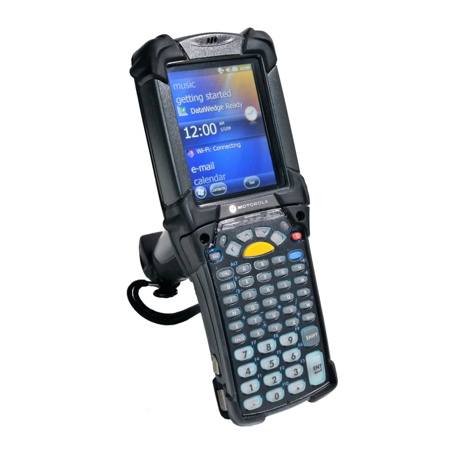
Chapter 1 Getting Started Introduction This chapter explains how to install and charge the batteries, replace the strap and start the MC9190-G for the first time. Indicator LED Bar Touch Screen Microphone Scan Button Keypad Headphone Jack Power Button Trigger... -
Page 18: Installing The Main Battery
NOTE Ensure the battery is fully inserted. Two audible clicks can be heard as the battery is fully inserted. A partially inserted battery may result in unintentional data loss. When a battery is fully inserted in a MC9190-G for the first time, upon first power up, the device boots and powers on automatically. -
Page 19: Charging The Battery
Battery Safety Guidelines on page 6-1. Charging the Main Battery and Memory Backup Battery Before using the MC9190-G for the first time, charge the main battery until the amber charge indicator light remains lit (see Table 1-1 on page 1-4 for charge status indications). -
Page 20: Charging Spare Batteries
MC9190-G User Guide • Cradles: The MC9190-G slips into the cradles for charging the battery in the MC9190-G (and spare batteries, where applicable). For detailed cradle setup and charging procedures refer to the MC9190 Integrator Guide. • Single Slot Serial/USB Cradle. -
Page 21: Removing The Main Battery
Removing the Main Battery Figure 1-3 Starting the MC9190-G Press the red Power button to turn on the MC9190-G. If the MC9190-G does not power on, perform a cold boot. Resetting the MC9190-G on page 2-22. NOTE When a battery is fully inserted in a MC9190-G for the first time, upon the MC9190-G’s first power up, the... -
Page 22: Calibrating The Screen
1 - 6 MC9190-G User Guide When the MC9190-G is powered on for the first time, it initializes its system. The splash screen appears for a short period of time. Calibrating the Screen To calibrate the screen so the cursor on the touch screen aligns with the tip of the stylus: Using the stylus carefully press and briefly hold the tip of stylus on the center of each target that appears on the screen. -
Page 23: Battery Management
Figure 1-4 Battery Management Battery Saving Tips • Leave the MC9190-G connected to AC power at all times when not in use. • Set the MC9190-G to turn off after a short period of non-use. • Set the display to turn off or dim backlight. -
Page 24: Changing The Keypad Backlight Settings
1 - 8 MC9190-G User Guide On devices with Windows CE 6.0, tap > > > > Start Settings Control Panel Backlight Battery Power On devices with Windows Mobile 6.5, tap > > > > Start Settings System Backlight Battery Power... -
Page 25: Bluetooth Radio With Stonestreet One Stack Enabled
Getting Started 1 - 9 Fusion Signal Strength Icon Fusion Signal Strength Icon Figure 1-5 To turn the radio back on, tap the Fusion Signal Strength icon on the task tray and select Enable Radio. The red X disappears from the icon indicating that the radio is enabled (on). Bluetooth Radio with StoneStreet One Stack Enabled To turn off the Bluetooth radio, tap the Bluetooth icon in the task tray and select Disable Bluetooth. - Page 26 1 - 10 MC9190-G User Guide...
-
Page 27: Chapter 2 Operating The Mc9190-G
Chapter 2 Operating the MC9190-G Introduction This chapter explains the physical buttons, status icons and controls on the MC9190-G, how to use the MC9190-G, including instructions for powering on and resetting, using the stylus and a headset, entering information and data capture. - Page 28 Double tapping on this icon opens the Power Properties window. AC Plug: Indicates that the battery is fully charged and the MC9190-G is running on external power. Battery: This icon indicates that the battery is fully charged (100% charged).
-
Page 29: Start Menu
Bluetooth radio and generate a transferred between a host server and Bluetooth address bar code. the MC9190-G. Refer to the MC9190-G Integrator Guide for more information. BTScanner CtlPanel: Set com port to Command Prompt: Opens a DOS use with a Bluetooth scanner. -
Page 30: Control Panel
Bluetooth Device Properties: Launch brightness and power settings. the Bluetooth application. Certificates: See information about DataWedge: Sample scanning certificates installed on the MC9190-G. application. Icon appears after installation. Date/Time: Change date, time and time Device Management: Enables zone information. downloading and installation of new software packages. -
Page 31: Windows Mobile 6.5
Touch the screen to stop scrolling. Home Screen The default home screen on the MC9190-G is the Windows Mobile Home screen. The Home screen contains a Status Bar at the top of the screen and a Tile Bar at the bottom of the screen. - Page 32 2 - 6 MC9190-G User Guide Status Bar Today Screen Tile Bar Open the Start Menu Tiles Windows Mobile Home Screen Figure 2-2 Touch and hold the screen with your finger and move the Home screen up and down. As the application names move under the Information Status bar, information relevant to that application appear in the bar.
-
Page 33: Classic Today Screen
Operating the MC9190-G 2 - 7 Moving Information Status Bar Figure 2-4 Application Icon Application Information Information Bar Example Figure 2-5 To customize the screen, tap > > . On the horizontal scroll, use to customize Home Settings Today Appearance the background and the to change the display format. -
Page 34: Status Bar
Bluetooth Communication: Indicates that the MC9190-G is communicating with another Bluetooth device (Displays only if the StoneStreet One Bluetooth stack is enabled). ActiveSync: Indicates an active serial connection between the MC9190-G and the development computer. DataWedge Running: Indicates that the DataWedge application is running. - Page 35 Operating the MC9190-G 2 - 9 Notifications Connectivity Audio Battery Battery Clock Status Bar Icons Figure 2-8 Status Bar Icons Table 2-5 Icon Description Icon Description Notifications Indicates a reminder of an upcoming calendar Notification that one or more instant messages event.
-
Page 36: Tile Bar
2 - 10 MC9190-G User Guide Icon Bar Icon Bar Figure 2-9 Icon Bar Icons Table 2-6 Icon Description Magnify: Enlarges the screen. Connectivity: Displays the Connectivity dialog box. Volume: Displays the Volume dialog box. Power: Displays the Power window. - Page 37 Operating the MC9190-G 2 - 11 Programs on the Start Screen Table 2-7 Icon Description Icon Description Home: Displays the Home screen. Text: Send an SMS text message. Contacts: Keep track of friends and E-mail: Send an Email. colleagues. Internet Explorer: Browse Web and...
- Page 38 2 - 12 MC9190-G User Guide Programs on the Start Screen (Continued) Table 2-7 Icon Description Icon Description Help: Access on-line Help topics. Task Manager: Enables viewing of memory and CPU allocations and stops running processes. Refer to the Microsoft Applications for Windows Mobile 6 User Guide for more information.
- Page 39 Description Icon Description Clock & Alarms: Set the device clock to Lock: Set a password for the MC9190-G. the date and time of your locale. Alarms can also be set at specified days and times of a week. Home: Customize the appearance of the Sounds &...
-
Page 40: Speaker Icon
2 - 14 MC9190-G User Guide Setting Applications (Continued) Table 2-8 Icon Description Icon Description Backlight: Set display backlight Customer Feedback: Submit feedback on brightness and time-out settings. the Windows Mobile 6 software. Error Reporting: Enable or disable the Encryption: Allow files on a storage card Microsoft’s error reporting function. -
Page 41: Locking The Mc9190-G
Lock the MC9190-G by disabling key presses and screen tap or by requiring a password. Locking the MC9190-G turns off keyboard and touch screen functionality. This is helpful when the MC9190-G is turned on and you want to prevent accidental key presses. -
Page 42: Locking With Strong Password
MC9190-G. Password If the MC9190-G is configured to connect to a network, use a strong (difficult to figure out) NOTE password to help protect network security. Password cracking tools continue to improve and the computers used to crack passwords are more powerful than ever. -
Page 43: Led Indicators
In the horizontal scroll, select Hint. Enter a hint to remember the password if you forget it. In the text box, enter a hint for a password reminder. LED Indicators The MC9190-G has an LED Indicator Bar that contains LEDs that indicate scanning and charging status. Table 2-9 describes the LED indications. -
Page 44: Keypads
2 - 18 MC9190-G User Guide Keypads The MC9190-G has the following interchangeable modular keypads: • 28-key keypad • 43-key keypad • 53-key keypad • 3270 Emulator • 5250 Emulator • VT Emulator. Refer Appendix C, Keypads to for detailed information on each keypad. -
Page 45: Using The Power Button
Using the Power Button Press the red Power button to turn the MC9190-G screen on and off (suspend mode). The MC9190-G is on when the screen is on and the MC9190-G is in suspend mode when the screen is off. For more information, see... -
Page 46: Windows Mobile 6.5 Devices
2 - 20 MC9190-G User Guide Signal Strength Icon Wireless Application Menu Figure 2-17 Windows Mobile 6.5 Devices On devices with Windows Mobile, access the Wireless launcher from the Home screen. Select the NOTE Fusion plug-in and then tap the Fusion Menu button. -
Page 47: Interactive Sensor Technology
It can also be used to keep the MC9190-G active while it is in movement to prevent it from quickly going into suspend mode while in use. -
Page 48: Using A Wired Headset
Resetting the MC9190-G Windows CE 6.0 Devices There are two reset functions, warm boot and cold boot. A warm boot restarts the MC9190-G by closing all running programs. A cold boot also restarts the MC9190-G, but erases all stored records and entries in RAM. Data saved in flash memory or a memory card is not lost. -
Page 49: Performing A Cold Boot
While the battery is partially released, simultaneously press and release the handle trigger and the Power button. Push the battery to fully re-insert it in the MC9190-G. One audible click can be heard as the battery is fully inserted. The MC9190-G initializes. -
Page 50: Battery Health
2 - 24 MC9190-G User Guide Push the battery to fully re-insert it in the MC9190-G. One audible click can be heard as the battery is fully inserted. The MC9190-G initializes. Battery Health The health of the battery can be viewed on the MC9190-G Power applet. Tap Start > Settings > Power icon >... - Page 51 Operating the MC9190-G 2 - 25 Wakeup Default Settings (Continued) Table 2-11 Condition for Wakeup Power Button Automatic Time-out Key is pressed. Audio Jack Audio Button...
- Page 52 2 - 26 MC9190-G User Guide...
-
Page 53: Chapter 3 Data Capture
Successful decode. Laser Scanning To read a bar code, a scan-enabled application is required. The MC9190-G with Windows Mobile contains the DataWedge application and MC9190-G with Windows CE contains the DataWedge and ScanSamp2 Example applications that allows the user to enable the scanner to decode bar code data and display the bar code content. -
Page 54: Scanning Considerations
Practice quickly shows what tolerances to work within. NOTE Contact the Motorola Enterprise Mobility Support Center if chronic scanning difficulties develop. Decoding of properly printed bar codes should be quick and effortless. -
Page 55: Operational Modes
(either 1D or 2D). • Image Capture Mode: Use this mode to capture an image within the MC9190-G’s field of view. This is useful for capturing signatures or images of items like damaged boxes. -
Page 56: Image Capture
Release the scan button. Image Capture To capture an image, an image capture application is required. The MC9190-G with Windows CE contains the ImagerSample application that allows the user to enable the scanner to capture an image and display the image. -
Page 57: Datawedge
3 - 5 Press the trigger or scan button. The captured image appears on the screen. DataWedge NOTE By default, DataWedge is not installed on the MC9190-G. Refer to the MC9190-G Integrator Guide for installation instructions. Enable DataWedge To enable DataWedge: On Windows Mobile, tap Start >... -
Page 58: Using The Rs507 Hands-Free Imager
Tap Generate Local BD Address Barcode. A bar code displays. NOTE If the MC9190-G with Windows CE is set to VGA mode the RS507 cannot read the bar code due to the smaller bar code size. Refer to the RS507 Hands-free Imager Product Reference Guide for instruction for printing a pairing bar code. -
Page 59: Chapter 4 Using Bluetooth
Motorola mobile computers to operate in any infrastructure. The Bluetooth radio in this MC9190-G operates as a Class 2 device power class. The maximum output power is 2.5mW and the expected range is 32.8 feet (10 meters). A definition of ranges based on power class is difficult to... -
Page 60: Security
Motorola EMDK for more information. Bluetooth Configuration By default, the MC9190-G is configured to using the Microsoft stack. Refer to the MC9190-G Integrator Guide, for information on switching between the Microsoft Bluetooth stack and the StoneStreet One Bluetooth stack. Table 4-1... -
Page 61: Bluetooth Power States
With StoneStreet One Bluetooth Stack Performing a cold boot on the MC9190-G turns off Bluetooth after initialization (which takes a few moments). It is normal to see the Bluetooth icon appear and disappear, as well as a wait cursor, when initialization proceeds in all... -
Page 62: Warm Boot
If there is an active Bluetooth connection between the MC9190-G and another Bluetooth device and there is no data activity, the MC9190-G will timeout. However, if the user presses the Power button on the MC9190-G, the MC9190-G will suspend and upon receiving data from a remote Bluetooth device, the MC9190-G will wake from suspend mode. -
Page 63: Using Microsoft Bluetooth Stack With Windows Mobile 6.5
Turn off the Bluetooth radio to save power or if entering an area with radio restrictions (e.g., an airplane). When the radio is off, other Bluetooth devices cannot see or connect to the MC9190-G. Turn on the Bluetooth radio to exchange information with other Bluetooth devices (within range). -
Page 64: Available Services
After the passcodes have been accepted on both sides, you have a trusted (“paired”) connection. Available Services NOTE Some devices might not require a PIN. This depends upon the device’s authentication. The MC9190-G with Microsoft Bluetooth stack and Windows Mobile 6.5 offers the following services: • OBEX Object Push via Beam •... -
Page 65: Serial Port Services
Select Beam File. The MC9190-G searches for Bluetooth devices in the area. Tap Tap to send next to the Bluetooth device to send the file to. The MC9190-G communicates with the device and send the file. When completed, Tap to send changes to Done. -
Page 66: Activesync Using Serial Port Services
4 - 8 MC9190-G User Guide Tap Next. NOTE If Smart-pairing is configured and the device is requesting one of the pre-defined PINs, the Enter Passcode window does not appear. Enter the Passcode and the tap Next. The device is added to the Bluetooth list. - Page 67 On the Allow connections to one of the following drop-down list, select the COM port with the number you noted earlier. On the MC9190-G, tap Start > Programs > ActiveSync. Tap Menu > Connect via Bluetooth. Synchronization is automatically initiated. The ActiveSync icon appears on the lower right corner of the Today screen.
-
Page 68: Using Microsoft Bluetooth Stack With Windows Ce 6.0
Discovering Bluetooth Device(s) The MC9190-G can receive information from discovered devices without bonding. However, once bonded, the MC9190-G and a bonded device exchange information automatically when you turn the Bluetooth radio on. See Pairing with Discovered Device(s) on page 4-26 for more information. -
Page 69: Available Services
NOTE In order to connect to the Bluetooth device, the application must create the connection to the remote device. Please refer to the MSDN Help for detailed information. The MC9190-G with Microsoft Bluetooth stack and Windows CE 6.0 only supports the Serial Port service. -
Page 70: Using Bluetooth Stonestreet One Bluetooth Stack
Turn off the Bluetooth radio to save power or if entering an area with radio restrictions (e.g., an airplane). When the radio is off, other Bluetooth devices cannot see or connect to the MC9190-G. Turn on the Bluetooth radio to exchange information with other Bluetooth devices (within range). -
Page 71: Modes
Discovering Bluetooth Device(s) The MC9190-G can receive information from discovered devices without bonding. However, once bonded, the MC9190-G and a bonded device exchange information automatically when you turn the Bluetooth radio on. See Pairing with Discovered Device(s) on page 4-26 for more information. - Page 72 BTExplorer searches for Bluetooth devices in the area. The discovered devices display in the Select Remote Device window. Select Remote Device Window Figure 4-6 Select a device from the list and tap Next. The MC9190-G searches for services on the selected Bluetooth device.
-
Page 73: Available Services
Using Bluetooth 4 - 15 Device Services Figure 4-7 NOTE If the MC9190-G discovers a service but the service is not supported, the service icon is grayed-out. Select a service from the list and press Next. Connection Favorite Options Window Figure 4-8 In the Favorite Name text box, enter a name for this service that will appear in the Favorite window. -
Page 74: File Transfer Services
Select the action to perform: • New - create a new file or folder on the remote device • Delete - delete the selected file on the remote device. • Get File - copy the file from the remote device to the MC9190-G. -
Page 75: Connecting To The Internet Using An Access Point
Using Bluetooth 4 - 17 • Put File - copy a file from the MC9190-G to the remote device. Creating a New File or Folder To create a new folder or file on the remote device: Tap and hold on the screen and select New > Folder or New > File. The Create New Folder or Create New File window appears. -
Page 76: Dial-Up Networking Services
NOTE Network Access profile is not supported. Dial-Up Networking Services Dial-up networking allows the user to connect the MC9190-G to a Bluetooth Phone and use the Bluetooth Phone as a modem to connect to an office network or ISP. Before setting up dial-up networking, obtain dial-up information and other necessary settings (username, password and domain name, if required) for the office network or ISP. -
Page 77: Add A Dial-Up Entry
Ensure the MC9190-G is discoverable and connectable. See Device Info Tab on page 4-27. Ensure that the OBEX Object Push profile is enabled on the MC9190-G. See Profiles Tab on page 4-31 more information. NOTE If favorite connections have already been created, the Favorites screen displays. If no favorite connections have been created, the New Connection Wizard screen displays. - Page 78 4 - 20 MC9190-G User Guide Sending a Contact To send a contact to another device: NOTE Prior to sending and receiving contacts, a default contact must be set up before attempting to send a contact. Tap and hold on OBEX Object Push and select Connect.
- Page 79 Using Bluetooth 4 - 21 NOTE Prior to swapping contacts, a default contact must be set up before attempting to send a contact. Ensure that the MC9190-G is connectable. Tap and hold on OBEX Object Push and select Connect. OBEX Object Push Window Figure 4-13 In the Action: drop-down list, select Swap Contact Information.
- Page 80 4 - 22 MC9190-G User Guide OBEX Object Push Window Figure 4-14 In the Action: drop-down list, select Fetch Contact information. Tap OK. The contact on the other device is copied. Sending a Picture To send a picture to another device: Tap and hold on OBEX Object Push and select Connect.
-
Page 81: Headset Services
Use the Connection Wizard to search for a Bluetooth headset. Select the device and tap Next. Select the Headset service name and select Connect. The MC9190-G connects to the headset. Refer to the headset user manual for instructions on communicating with a Bluetooth device. -
Page 82: Serial Port Services
4 - 24 MC9190-G User Guide Serial Port Services Use the wireless Bluetooth serial port connection as you would a physical serial cable connection. Configure the application that will use the connection to the correct serial port. To establish a serial port connection: Use the Connection Wizard to search for a Bluetooth serial device. -
Page 83: Personal Area Network Services
NOTE This profile supports Ad-hoc and PAN User. Network Access Profile is not supported. Connect two or more Bluetooth devices to share files, collaborate, or play multi-player games. To establish a Personal Area Network connection: Ensure that the Personal Area Networking profile is enabled on the MC9190-G. See Profiles Tab on page 4-31 for more information. -
Page 84: Connect To A Hid Device
Tap Connect. The MC9190-G connects to the high-quality audio headset. Connect to a HID Device The MC9190-G can connect to an Human Interface Device (HID) device such as a Bluetooth keyboard: Ensure the MC9190-G is connectable (required when automatic re-connect is initiated). See... -
Page 85: Bluetooth Settings
A confirmation dialog appears. Tap Yes. Accepting a Pairing When a remote device wants to pair with the MC9190-G, enter a PIN when requested to grant permission. Ensure that the MC9190-G is set to discoverable and connectable. See Bluetooth Settings on page 4-27. -
Page 86: Services Tab
4 - 28 MC9190-G User Guide Services Tab NOTE Ensure that the MC9190-G is discoverable and connectable when remote devices use MC9190-G services. Use the Services tab to add or delete Bluetooth services. BTExplorer Settings - Services Tab Figure 4-19 To add a service: Tap Add. - Page 87 Service Security - Select the type of security from the drop-down list. Options are None, Authenticate, or Authenticate/Encrypt. • Do not allow clients to push objects - Disables clients from pushing objects to the MC9190-G. • Inbox Directory - Select a directory where another Bluetooth device can store files.
-
Page 88: Security Tab
Use the Discovery tab to set and modify discovered devices. • Inquiry Length - Sets the amount of time the MC9190-G takes to discover Bluetooth devices in the area. • Name Discovery Mode - Select either Automatic or Manual to automatically attempt to discover a Bluetooth device's name after finding the device. -
Page 89: Virtual Com Port Tab
• Link Supervision Timeout - Sets the amount of time that the MC9190-G will wait for a device to come back into range after it has gone out of range. If the device does not come back into range by the set time, the MC9190-G drops the connection. - Page 90 4 - 32 MC9190-G User Guide • Apply Text Style - Select the text style to apply to the connection text. • Apply Text Color - Select the text color to apply to the connection text.
-
Page 91: Chapter 5 Accessories
Chapter 5 Accessories Introduction The MC9190-G accessories provide a variety of product support capabilities. Table 5-1 lists the accessories available. MC9190-G Accessories Table 5-1 Accessory Part Number Description Cradles Single Slot Serial/USB CRD9000-1001SR Charges the MC9190-G main battery and a spare Cradle battery. - Page 92 Jack Screws Paxar Printer Cable 25-62168-01R Connects the MC9100-G to a Paxar printer. O’Neil Printer Cable 25-62169-01R Connects the MC9190-G to an O’Neil printer. Zebra Printer Cable 25-62170-02R Connects the MC9190-G to a Zebra printer. Modem Cable 25-63856-01R Allows the Single Slot Serial/USB cradle to be used as a modem cradle.
- Page 93 Shoulder Strap 58-40000-007R Universal shoulder strap for holster. Snap-on Cable Adapter Module ADP9000-110R Attaches to the bottom of the MC9190-G and (CAM) provides power (5 VDC 350 mA) for use with the LS3408ER scanner. Cable Adapter Module ADP9000-100R Attaches to the bottom of the MC9190-G and...
- Page 94 Table 5-1 Accessory Part Number Description Rugged Cable Headset RCH50 Rugged headset RCH50 Adapter Cable 25-124387-01R RCH50 adapter cable for standard 3-pole, 2.5mm barrel jack used with MC9190-G. UBC2000 Wall Mount Kit KT-32665-01R Use for mounting UBC2000 onto a wall.
-
Page 95: Secure Device (Sd) Card
The SD card provides secondary non-volatile storage. The SD card is located under the keypad. CAUTION Do not remove the keypad while the MC9190-G is on and do not operate the MC9190-G with the keypad detached. Follow proper ESD precautions to avoid damaging the SD card. Proper ESD precautions include, but are not limited to, working on an ESD mat and ensuring that the operator is properly grounded. -
Page 96: Single Slot Serial/Usb Cradle
(e.g., a printer). NOTE When a MC9190-G with Microsoft Mobile 6.5 is placed in the cradle and an ActiveSync connection is made, the WLAN radio (if applicable) is disabled. This is a Microsoft security feature to prevent connection to two... - Page 97 The the Single Slot Serial/USB Cradle can charge the MC9190-G’s main battery and a spare battery simultaneously. The MC9190-G’s amber charge LED, located in the Indicator LED Bar, shows the status of the battery charging in the MC9190-G. See Table 1-1 on page 1-4 for charging status indications.
-
Page 98: Four Slot Ethernet Cradle
MC9190-G with corporate databases.) • Simultaneously charges up to four batteries in the MC9190-G. The MC9190-G’s amber charge LED, located in the Indicator LED Bar, shows the status of the battery charging in the MC9190-G. See Table 1-1 on page 1-4 for charging status indications. -
Page 99: Four Slot Charge Only Cradle
Provides 12 VDC power for operating the MC9190-G. • Simultaneously charges up to four batteries in the MC9190-G. The MC9190-G’s amber charge LED, located in the Indicator LED Bar, shows the status of the battery charging in the MC9190-G. See Table 1-1 on page 1-4 for charging status indications. -
Page 100: Four Slot Spare Battery Charger
Solid Amber Charging complete. Magnetic Stripe Reader This section describes how to set up and use the snap-on MSR with the MC9190-G. The MSR snaps on to the bottom of the MC9190-G and can be easily removed when not in use. -
Page 101: Attaching And Removing
Allows the MC9190-G to capture data from magnetic stripe cards. (To download MSR data capture software, visit: http://supportcentral.motorola.com.) NOTE When a MC9190-G with Windows Mobile 6.5 is connected to a host computer through the MSR and an ActiveSync connection is made, the WLAN radio (if applicable) are disabled. This is a Microsoft security feature to prevent connection to two networks at the same time. -
Page 102: Setup
Attaching the MSR Figure 5-7 To remove, squeeze the latch grips and pull the MSR from the MC9190-G. NOTE Remove the MSR from the bottom of the MC9190-G before using a cradle for charging and communication. Setup Into Cigarette Lighter... -
Page 103: Battery Charging Indicators
NOTE Batteries must be charged within the 32° to 104° F (0° to +40° C) ambient temperature range. The MC9190-G’s amber charge LED, located in the Indicator LED Bar, shows the status of the battery charging in the MC9190-G. See Table 1-1 on page 1-4 for charging status indications. - Page 104 Swipe the magnetic stripe card through the MSR, ensuring the magnetic stripe on the card faces the MC9190-G. The card may be swiped in either direction, from left to right or from right to left. For best results, gently press down on the card while swiping to ensure contact with the bottom of the reader.
-
Page 105: Cable Adapter Module
Accessories 5 - 15 Cable Adapter Module This section describes how to set up and use the snap-on CAM with the MC9190-G. The CAM snaps on to the bottom of the MC9190-G and can be easily removed when not in use. -
Page 106: Setup
Attaching the CAM Figure 5-12 To remove, squeeze the latch grips and pull the CAM from the MC9190-G. NOTE Remove the CAM from the bottom of the MC9190-G before using a cradle for charging and communication. Setup Into Cigarette Lighter... -
Page 107: Battery Charging Indicators
NOTE Batteries must be charged within the 32° to 104° F (0° to +40° C) ambient temperature range. The MC9190-G’s amber charge LED, located in the Indicator LED Bar, shows the status of the battery charging in the MC9190-G. See Table 1-1 on page 1-4 for charging status indications. -
Page 108: Universal Battery Charger (Ubc) Adapter
5 - 18 MC9190-G User Guide Universal Battery Charger (UBC) Adapter CAUTION Ensure that you follow the guidelines for battery safety described in Battery Safety Guidelines on page 6-1. This section describes how to use the UBC adapter to charge a spare battery. - Page 109 The battery was deeply discharged and is being trickle charged to bring the voltage up to the operating level. After operating level voltage is achieved the battery charges normally. FAULT Yellow Charging error, check placement of MC9190-G/spare battery. CHARGING Yellow Normal charge.
-
Page 110: Modem Dongle
Modem Dongle Figure 5-17 The Modem Dongle enables data communication between the MC9190-G and a host computer, remotely through the phone lines, and synchronizes information between the MC9190-G and a host computer. The following items are required for a modem connection: •... -
Page 111: Setup
Male 15-pin connector Phone port Line In port Phone cord Phone cord Modem Dongle Connection - MC9190-G Figure 5-18 Do not connect the modem's 15-pin connector into a VGA port of a host computer. CAUTION Using the Correct Telephone Line Type Use a standard analog phone line, as in most households. -
Page 112: Connecting To The Single Slot Serial/Usb Cradle
NOTE If using a phone, connect the cord from the phone to the Phone port on the modem. Modem LED Indicator Table 5-5 Indication Modem is not properly connected to the MC9190-G; modem is not receiving power. Green Modem is connected to the MC9190-G and is receiving power. Solid Amber... -
Page 113: Forklift Cradle
• provides power for charging a docked MC9190-G. • provides one serial and one USB port for data communication between a docked MC9190-G and an external device (e.g., a scanner/printer). • provides power to each port (500mA at 5V). Both ports can be used simultaneously. - Page 114 5 - 24 MC9190-G User Guide MC9190-G locking mechanism stylus holder (and stylus) mobile computer release button MC9190-G handle slot power-in port Serial port USB port Forklift Cradle Figure 5-20...
-
Page 115: Mc9190-G Insertion And Removal
MC9190-G Insertion and Removal To insert the MC9190-G into the fork lift cradle, place the bottom of the MC9190-G into the bottom of the fork lift cradle, then press the MC9190-G back into the cradle until the release button locks it in place. -
Page 116: Using The Locking Mechanism
Using the Locking Mechanism The locking mechanism prohibits the removal of the MC9190-G from the fork lift cradle. To use the locking mechanism, with the MC9190-G in the fork lift cradle, place the locking mechanism into the position behind the release button. -
Page 117: Supported Scanners
Accessories 5 - 27 Supported Scanners The forklift cradle supports the following scanners: • LS3408-FZ20005R (requires USB cable 25-71918-01R or serial cable 25-71917-02R) • LS3408-ER20005R (requires USB cable 25-71918-01R or serial cable 25-71917-02R) • LS3478 scanner with FLB3478-C0007WR cradle (requires USB cable 25-71918-01R or serial cable 25-71917-02R) ®... - Page 118 5 - 28 MC9190-G User Guide...
-
Page 119: Chapter 6 Maintenance & Troubleshooting
For trouble-free service, observe the following tips when using the MC9190-G: • Protect the MC9190-G from temperature extremes. Do not leave it on the dashboard of a car on a hot day, and keep it away from heat sources. •... -
Page 120: Cleaning
Read warning label on compressed air and alcohol product before using. If you have to use any other solution for medical reasons please contact Motorola for more information. Avoid exposing this product to contact with hot oil or other flammable liquids. If such exposure WARNING occurs, unplug the device and clean the product immediately in accordance with these guidelines. -
Page 121: Harmful Ingredients
Cleaning Instructions Do not apply liquid directly to the MC9190-G. Dampen a soft cloth or use pre-moistened wipes. Do not wrap the device in the cloth or wipe, but gently wipe the unit. Be careful not to let liquid pool around the display window or other places. -
Page 122: Cleaning Cradle Connectors
MC9190-G User Guide Rub the cotton portion of the cotton tipped applicator back-and-forth across the connector on the bottom of the MC9190-G. Do not leave any cotton residue on the connector. Repeat at least three times. Use the cotton tipped applicator dipped in alcohol to remove any grease and dirt near the connector area. -
Page 123: Troubleshooting
Installing the Main not installed Battery on page 1-2. properly. System crash. Perform a warm boot. If the MC9190-G still does not turn on, perform a cold boot. See Resetting the MC9190-G on page 2-22. Rechargeable Battery failed. Replace battery. If the MC9190-G still does not operate, try a lithium-ion battery did warm boot, then a cold boot. - Page 124 MC9190-G is running on battery power, this period can be set to 30 sec., 1, 2, 3, 4, 5 or 6 minutes. If the MC9190-G is running on external power, this period can be set to 1, 2, 3, 5, 10, 15 and 30 minutes.
- Page 125 Distance between Ensure MC9190-G is within proper scanning range. exit window and bar code is incorrect. MC9190-G is not Ensure the MC9190-G is programmed to accept the type of bar programmed for the code being scanned. bar code. MC9190-G is not...
-
Page 126: Four Slot Spare Battery Charger
AC power too (if the MC9190-G is off and longer if the MC9190-G is operating). soon. For Windows Mobile 6.5 devices, view battery status by tapping Start >... -
Page 127: Cable Adapter Module
CAM was unplugged is fully depleted, it can take up to four hours to fully recharge a from AC power too battery (if the MC9190-G is off and longer if the MC9190-G is soon. operating). For Windows Mobile 6.5 devices, view battery status by tapping >... -
Page 128: Magnetic Stripe Reader
Confirm main battery is charging. If a charging. unplugged from AC power MC9190-G battery is fully depleted, it can take up to four hours to too soon. fully recharge a battery (if the MC9190-G is off and longer if the MC9190-G is operating). - Page 129 Reattach the MC9190-G to MSR and retransmit. communications, MSR during no data was communications. transmitted, or Incorrect cable See the System Administrator. transmitted data configuration. was incomplete. Communications software Perform setup as described in the MC9190-G Integrator Guide. is not installed or configured properly.
- Page 130 6 - 12 MC9190-G User Guide...
-
Page 131: Appendix A Specifications
Appendix A Specifications Technical Specifications The following tables summarize the MC9190-G’s intended operating environment and general technical hardware specifications. MC9190-G The following table summarizes the MC9190-G’s intended operating environment. Technical Specifications Table A-1 Item Description Physical and Environmental Characteristics Dimensions 9.1 in. - Page 132 Technical Specifications (Continued) Table A-1 Item Description Application PSDK and EMDK available through Motorola Support Central Web site. Development Data Capture SE960: 1D standard range scan engine Options SE1524-ER: 1D extended range scan engine reads up to 45 ft./13.72 m away SE4600: Extended range omnidirectional 1D/2D imaging engine reads 1D and 2D symbols as close as 8 in./20.32 cm and as far as 30 ft./9.14 m...
- Page 133 Supports extensive line of Motorola approved printers Charger 4-slot battery charger, 4-slot universal battery charger Other Cable Adapter Module; snap-on Magnetic Stripe Reader; Modem module; full set of holsters; full Accessories set of cables, Motorola approved CAC Reader for government applications...
- Page 134 A - 4 MC9190-G User Guide Data Capture Options Table A-2 Item Description Laser Decode Capability Code 39 Code 128 Code 93 Codabar Code 11 Discrete 2 of 5 Interleaved 2 of 5 EAN-8 EAN-13 UPCA UPCE UPC/EAN supplementals Coupon Code...
-
Page 135: Appendix B Voice Quality Manager
Introduction The Voice Quality Manager (VQM) is a software package that resides on the MC9190-G. VQM enables a set of features for Voice over WiFi (VoWiFi) calls. The VQM user interface is designed to be intuitive and easy to use, so... -
Page 136: Audio Modes
B - 2 MC9190-G User Guide Tap the filename to enable VQM. Audio Modes The MC75A can be in any one of the seven different audio modes. The mode is visually indicated by the VQM icon on the title bar. -
Page 137: Voice Packet Prioritization
VQM icon. The only way to reconnect the Bluetooth headset to the device is by using the BTExplorer application. If the user taps the VQM icon when a wired headset is connected to the MC9190-G, the audio mode does not change. The audio continues to get routed to the wired headset. -
Page 138: Acoustic Echo Cancellation
B - 4 MC9190-G User Guide VQM detects if there is an ongoing Voice over WiFi (VoWiFi) call, and if so, marks outgoing voice packets (Only outgoing voice packets can be marked. The incoming voice packets have already been through the network, so it makes no sense to mark them.) as high-priority using DSCP. -
Page 139: Appendix C Keypads
Appendix C Keypads Introduction The MC9190-G has the following interchangeable modular keypads: • 28-key keypad • 43-key keypad • 53-key keypad • 3270 Emulator • 5250 Emulator • VT Emulator. The modular keypads can be changed in the field, as necessary, to support specialized applications. Refer to the... -
Page 140: 28-Key Keypad
The 28-key keypad contains a Power button, application keys, scroll keys and function keys. The keypad is color-coded to indicate the alternate function key (blue) values. Note that keypad functions can be changed by an application so the MC9190-G’s keypad may not function exactly as described. See Table C-1 on page C-3... - Page 141 Parm name = “RedKeyOverride” value = “xx”, where xx is the new APP key code. Refer to the MC9190-G Integrator Guide for instruction on updating the registry using XML Provisioning. This sends an APP key code, instead of their original key codes, when the green or red dot key is pressed.
- Page 142 Characteristic type =”HKEY_LOCAL_MACHINE\HARDWARE\DEVICEMAP\KEYBD” Para name = “SpecialEnterTabKey” value = 0 Refer to the MC9190-G Integrator Guide for instruction on updating the registry using XML Provisioning. Period/Decimal Point In default state, produces a period for alpha entries and a decimal point for numeric entries.
-
Page 143: 43-Key Keypad
The 43-key keypad contains a Power button, application keys, scroll keys and a function key. The keypad is color-coded to indicate the alternate function key (blue) values and the alternate ALPHA key (orange) values. Note that keypad functions can be changed by an application so the MC9190-G’s keypad may not function exactly as described. See... - Page 144 Parm name = “RedKeyOverride” value = “xx”, where xx is the new APP key code. Refer to the MC9190-G Integrator Guide for instruction on updating the registry using XML Provisioning. This sends an APP key code, instead of their original key codes, when the green or red dot key is pressed.
- Page 145 Notes application to exit. To make the applications work properly, create an XML Provisioning file with the following entries: Characteristic type =”HKEY_LOCAL_MACHINE\HARDWARE\DEVICEMAP\KEYBD” Para name = “SpecialEnterTabKey” value = 0 Refer to the MC9190-G Integrator Guide for instruction on updating the registry using XML Provisioning.
-
Page 146: 53-Key Keypad
The 53-key keypad contains a Power button, application keys, scroll keys and function keys. The keypad is color-coded to indicate the alternate function key (blue) values. Note that keypad functions can be changed by an application so the MC9190-G’s keypad may not function exactly as described. See Table C-3 on page C-9... - Page 147 Parm name = “RedKeyOverride” value = “xx”, where xx is the new APP key code. Refer to the MC9190-G Integrator Guide for instruction on updating the registry using XML Provisioning. This sends an APP key code, instead of their original key codes, when the green or red dot key is pressed.
- Page 148 Notes application to exit. To make the applications work properly, create an XML Provisioning file with the following entries: Characteristic type =”HKEY_LOCAL_MACHINE\HARDWARE\DEVICEMAP\KEYBD” Para name = “SpecialEnterTabKey” value = 0 Refer to the MC9190-G Integrator Guide for instruction on updating the registry using XML Provisioning.
-
Page 149: 3270 Emulator Keypad
3270 Emulator Keypad Figure C-4 NOTE The 3270 emulator keypad is only used when the MC9190-G is running the 3270 emulation software. When the MC9190-G is not running the 3270 emulation software, the 3270 keypad functions are the same as a 53-key keypad. - Page 150 Parm name = “GreenKeyOverride” value = “xx”, where xx is the new APP key code. Parm name = “RedKeyOverride” value = “xx”, where xx is the new APP key code. Refer to the MC9190-G Integrator Guide for instruction on updating the registry using XML Provisioning.
- Page 151 Notes application to exit. To make the applications work properly, create an XML Provisioning file with the following entries: Characteristic type =”HKEY_LOCAL_MACHINE\HARDWARE\DEVICEMAP\KEYBD” Para name = “SpecialEnterTabKey” value = 0 Refer to the MC9190-G Integrator Guide for instruction on updating the registry using XML Provisioning.
-
Page 152: 5250 Emulator Keypad
Figure C-5 NOTE The 5250 emulator configuration is only used when the MC9190-G is running the 5250 emulation software. When the MC9190-G is not running the 5250 emulation software, the 5250 keypad functions are the same as a 53-key keypad. - Page 153 Parm name = “GreenKeyOverride” value = “xx”, where xx is the new APP key code. Parm name = “RedKeyOverride” value = “xx”, where xx is the new APP key code. Refer to the MC9190-G Integrator Guide for instruction on updating the registry using XML Provisioning.
- Page 154 Notes application to exit. To make the applications work properly, create an XML Provisioning file with the following entries: Characteristic type =”HKEY_LOCAL_MACHINE\HARDWARE\DEVICEMAP\KEYBD” Para name = “SpecialEnterTabKey” value = 0 Refer to the MC9190-G Integrator Guide for instruction on updating the registry using XML Provisioning.
-
Page 155: Vt Emulator Keypad
Figure C-6 NOTE The VT emulator configuration is only used when the MC9190-G is running the VT emulation software. When the MC9190-G is not running the VT emulation software, the VT keypad functions are the same as a 53-key keypad. - Page 156 Parm name = “RedKeyOverride” value = “xx”, where xx is the new APP key code. Refer to the MC9190-G Integrator Guide for instruction on updating the registry using XML Provisioning. This sends an APP key code, instead of their original key codes, when the green or red dot key is pressed.
- Page 157 Notes application to exit. To make the applications work properly, create an XML Provisioning file with the following entries: Characteristic type =”HKEY_LOCAL_MACHINE\HARDWARE\DEVICEMAP\KEYBD” Para name = “SpecialEnterTabKey” value = 0 Refer to the MC9190-G Integrator Guide for instruction on updating the registry using XML Provisioning.
-
Page 158: Keypad Special Functions
C - 20 MC9190-G User Guide Keypad Special Functions The keypad special functions are color coded on the keypads. For example, on the 53-key keypad, the display backlight icon is blue indicating that the blue function key must be selected first to access the display backlight. On the 43-key keypad, the display backlight icon is white indicating that the display backlight is the default value for that key. -
Page 159: Special Characters
Keypads C - 21 Special Characters The keypads can be selected as necessary to support specialized applications. The keypads contain a Power button, application keys, scroll keys and function keys. The keypad is color-coded to indicate the alternate function key (blue) values and the alternate ALPHA key (orange) values. See Table C-8 for the special character generation. - Page 160 C - 22 MC9190-G User Guide Special Character Generation Map (Continued) Table C-8 Special Character 28-Key Keypad 43-Key Keypad 53-Key Keypad SHIFT - 9 (open parenthesis) SHIFT - 0 (close parenthesis) ‘ Blue Key - C (single quote) “ SHIFT - Blue Key - C...
- Page 161 Glossary Numeric 802.11. A group of wireless specifications developed by the Institute of Electrical and Electronics Engineers (IEEE). It specifies an over-the-air interface between a wireless client and a base station or between two wireless clients. 802.11a. Operates in the 5 GHz frequency range (5.125 to 5.85 GHz) with a maximum 54Mbit/sec. signaling rate. The 5 GHz frequency band is not as crowded as the 2.4 GHz frequency because it offers significantly more radio channels than the 802.11b and is used by fewer applications.
- Page 162 MD5 sum itself and compares the result with the value received from the peer. If the values match, the peer is authenticated. Cold Boot. A cold boot restarts the MC9190-G and erases all user stored records and entries. COM port. Communication port; ports are identified by number, e.g., COM1, COM2.
- Page 163 Decode. To recognize a bar code symbology (e.g., UPC/EAN) and then analyze the content of the specific bar code scanned. Device Configuration Package. The Motorola Device Configuration Package provides flash partitions, Terminal Configuration Manager (TCM) and the associated TCM scripts. With this package hex images that represent flash partitions can be created and downloaded to the MC9190-G.
- Page 164 Glossary - 4 MC9190-G User Guide IEC. International Electrotechnical Commission. This international agency regulates laser safety by specifying various laser operation classes based on power output during operation. IEC (825) Class 1. This is the lowest power IEC laser classification. Conformity is ensured through a software restriction of 120 seconds of laser operation within any 1000 second window and an automatic laser shutdown if the scanner's oscillating mirror fails.
- Page 165 They require external light to reflect their information to the user. Mobile Computer. In this text, mobile computer refers to the Motorola MC9190-G wireless computer. It can be set up to run as a stand-alone device, or it can be set up to communicate with a network, using wireless radio technology.
- Page 166 Glossary - 6 MC9190-G User Guide Router. A device that connects networks and supports the required protocols for packet filtering. Routers are typically used to extend the range of cabling and to organize the topology of a network into subnets. See Subnet.
- Page 167 TLS is the successor to the Secure Sockets Layer (SSL). Visible Laser Diode (VLD). A solid state device which produces visible laser light. Warm Boot. A warm boot restarts the MC9190-G by closing all running programs. All data that is not saved to flash memory is lost.
- Page 168 Glossary - 8 MC9190-G User Guide...
- Page 169 43-key keypad ......C-5 attaching MC9190-G strap ....1-6 5250 emulator keypad .
- Page 170 Index - 2 MC9190-G User Guide bonding two dimensional bar codes ....3-2 Bluetooth ......4-26 date/time .
- Page 171 Index - 3 imager. See data capture, imaging battery charging ....5-13, 5-18 imaging ........3-3 installation .
- Page 172 ......2-8 attaching to the MC9190-G ....1-6 wireless status icon .
- Page 174 1-800-927-9626 http://www.motorola.com MOTOROLA, MOTO, MOTOROLA SOLUTIONS and the Stylized M Logo are trademarks or registered trademarks of Motorola Trademark Holdings, LLC and are used under license. All other trademarks are the property of their respective owners. © 2011 by Motorola Solutions, Inc. All rights reserved.