
Related Manuals for Bosch Rexroth VT-VRPD-2


Summary of Contents for Bosch Rexroth VT-VRPD-2
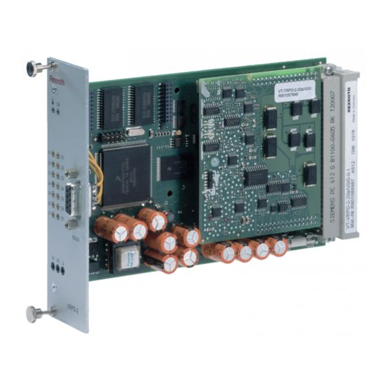
- Page 1 VT-VRPD-2 – Digital valve RE 30126-B/09. 1 3 Replaces: 08.07 amplifier for valve types 4WRE 6, component series 2X 4WRE 10, component series 2X Installation and Operation...
- Page 2 2/32 Bosch Rexroth AG | Hydraulics Installation and Operation | RE 30126-B/09.13...
-
Page 3: Table Of Contents
RE 30126-B/09.13 | Installation and Operation Hydraulics | Bosch Rexroth AG 3/32 Contents General ...................... 5 About this Manual ..................5 Additional Documentation .................... 5 Characters and Symbols ....................6 Scope of Supply ..................7 Requirements ..................... 7 Installing the VRPD .................. 8 Safety Requirements .................. - Page 4 4/32 Bosch Rexroth AG | Hydraulics Installation and Operation | RE 30126-B/09.13 Initial startup with BODAC ................ 22 VRPD Operation ..................23 Display/Input Keys and Connectors on the Front Panel ......23 Diagnostics Test Jacks ................24 Diagnostics ..................... 25 Diagnostic Options on the VRPD Controller Card ........
-
Page 5: General
RE 30126-B/09.13 | Installation and Operation Hydraulics | Bosch Rexroth AG 5/32 General 1 General About this Manual Before installing or operating your VRPD Controller card for the first time, you should read this Manual. Please note the safety requirements described in section 2.1. -
Page 6: Characters And Symbols
6/32 Bosch Rexroth AG | Hydraulics Installation and Operation | RE 30126-B/09.13 1 General Characters and Symbols The following characters and symbols are used in the manual: Action symbol: The text following this symbol describes actions. These should be performed, from top to bottom, in the given order. -
Page 7: Scope Of Supply
RE 30126-B/09.13 | Installation and Operation Hydraulics | Bosch Rexroth AG 7/32 General 1 Scope of Supply The equipment is packed in anti-static packaging to protect the controller card from electrostatic discharge. Observe instructions on the top side of the packaging. -
Page 8: Installing The Vrpd
8/32 Bosch Rexroth AG | Hydraulics Installation and Operation | RE 30126-B/09.13 2 Installing the VRPD Installing the VRPD Safety Requirements Operate the VRPD controller card only if it is not damaged and is in proper operating condition and is applied for its intended purpose. Observe all safety and hazard in- structions in the included documentation. -
Page 9: Personnel Selection And Qualifications
RE 30126-B/09.13 | Installation and Operation Hydraulics | Bosch Rexroth AG 9/32 Installing the VRPD 2 Personnel Selection and Qualifications Operation and Startup Operation and startup of the VRPD controller card requires specialized skills. There- fore this work should be performed only by properly trained individuals. -
Page 10: Repair And Troubleshooting
Bosch Rexroth AG | Hydraulics Installation and Operation | RE 30126-B/09.13 2 Installing the VRPD Bosch Rexroth also recommends shielding solenoid wiring. Do not use logical signals from the controller card (IE: “OK” signal) for switching machine safety circuits (see European Norm "Safety Requirements for Fluid Power Systems and Com- ponents"... -
Page 11: Transport, Storage And Handling The Controller Card
RE 30126-B/09.13 | Installation and Operation Hydraulics | Bosch Rexroth AG 11/32 Installing the VRPD 2 Transport, Storage and Handling the Controller Card The packaging contains notes on handling of the controller card. These must be strict- ly followed. SDLC... -
Page 12: Card Installation
12/32 Bosch Rexroth AG | Hydraulics Installation and Operation | RE 30126-B/09.13 2 Installing the VRPD Card Installation Remove the card from its packaging only at a protected work place. Do not touch any electrical components when placing the controller card in its proper card holder as shown in Fig. -
Page 13: Edge Connector Terminals And Pin Assignments
RE 30126-B/09.13 | Installation and Operation Hydraulics | Bosch Rexroth AG 13/32 Installing the VRPD 2 Edge Connector Terminals and Pin Assignments The edge connector is a 64-pin, Type G (DIN 41612). The pin assignments for the edge connector are not fully downward compatible with older amplifier products. - Page 14 14/32 Bosch Rexroth AG | Hydraulics Installation and Operation | RE 30126-B/09.13 2 Installing the VRPD Row b Description Type AI3+ n. c. AI3- n. c. AI2+ Differential input AI2- Differential input AI1+ n. c. AI1- n. c. AI4+ Differential input...
- Page 15 RE 30126-B/09.13 | Installation and Operation Hydraulics | Bosch Rexroth AG 15/32 Installing the VRPD 2 Row z Description Type Solenoid a + Solenoid a - Solenoid b + MB - Solenoid b - Shield Shield L1O- LVDT valve pin 2...
- Page 16 16/32 Bosch Rexroth AG | Hydraulics Installation and Operation | RE 30126-B/09.13 2 Installing the VRPD Row f Description Type DO 7 n. c. SSI Clk + n. c. SSI Clk - n. c. AI7+ n. c. AI7- n. c.
-
Page 17: Installation Local Bus
RE 30126-B/09.13 | Installation and Operation Hydraulics | Bosch Rexroth AG 17/32 Installing the VRPD 2 Installation Local Bus The local bus is used to connect the individual amplifier cards of the HACD family. Up to 32 cards can be connected. Each amplifier must be assigned a clear bus ad- dress. -
Page 18: Connecting The Proportional Valve
18/32 Bosch Rexroth AG | Hydraulics Installation and Operation | RE 30126-B/09.13 2 Installing the VRPD Connecting the proportional valve When connecting the proportional valve, be sure that the solenoid cables are routed separately from the inductive position transducers. It is strongly recommended that the solenoid cable is shielded. -
Page 19: Connecting The Valve Position Transducer
RE 30126-B/09.13 | Installation and Operation Hydraulics | Bosch Rexroth AG 19/32 Installing the VRPD 2 Connecting the valve position transducer Connection for the valve position transducer is shown in the following illustration. Valve position feedback connection VPCD_06 Fig. 5 Connecting the valve transducer The transducer is connected using a 4-pole cable connector Pg7-G5W1F, which can be ordered separately under material number R900023126. -
Page 20: Startup Of The Vrpd Controller Card
20/32 Bosch Rexroth AG | Hydraulics Installation and Operation | RE 30126-B/09.13 3 Startup of the VRPD Controller Card Startup of the VRPD Controller Card Preparing for Use The startup procedure for the VRPD controller card depends on a variety of factors that are determined by the individual application. -
Page 21: Installing Bodac Software
RE 30126-B/09.13 | Installation and Operation Hydraulics | Bosch Rexroth AG 21/32 Startup of the VRPD Controller Card 3 Installing BODAC software BODAC software (ordering code SYS-HACD-BODAC-01 ordering number R900777335) can download via Internet (www.boschrexroth.com/hacd). This software is used for initial startup and as a convenient configuration and monitoring tool for the controller card. -
Page 22: Initial Startup With Bodac
22/32 Bosch Rexroth AG | Hydraulics Installation and Operation | RE 30126-B/09.13 3 Startup of the VRPD Controller Card Initial startup with BODAC After installing the VRPD controller card in a rack, as described in section 2.4 "Card Installation", and all initial steps have been completed properly, the card startup is ready. -
Page 23: Vrpd Operation
RE 30126-B/09.13 | Installation and Operation Hydraulics | Bosch Rexroth AG 23/32 VRPD Operation 4 VRPD Operation Display/Input Keys and Connectors on the Front Panel You can use the display, input keys and connectors on the front panel of the VRPD to check parameters and settings, attach diagnostic instruments and connect the card to a PC. -
Page 24: Diagnostics Test Jacks
24/32 Bosch Rexroth AG | Hydraulics Installation and Operation | RE 30126-B/09.13 4 VRPD Operation Serial port The serial port on the front panel is configured as a standard RS-232 port using a 9- pin D-Sub female connector. A standard 9 pin serial data cable is used to connect the serial port to a PC. -
Page 25: Diagnostics
RE 30126-B/09.13 | Installation and Operation Hydraulics | Bosch Rexroth AG 25/32 Diagnostics 5 Diagnostics Diagnostic Options on the VRPD Controller Card Diagnostics terminal The diagnostic test jacks on the front panel of the VRPD controller card (see section 4.1 Display/Input Keys and Connectors on the Front Panel, Fig. 7 ) provide two analog... -
Page 26: Detecting Errors
26/32 Bosch Rexroth AG | Hydraulics Installation and Operation | RE 30126-B/09.13 6 Detecting Errors Detecting Errors Error Messages Error message Description Reference voltage +10V (b32) or Reference voltage –10V +/- 10V Source (b30) outside the specified range. Power 24V Power supply Ub (z30) less than Ub min. -
Page 27: Changing Fuses
RE 30126-B/09.13 | Installation and Operation Hydraulics | Bosch Rexroth AG 27/32 Detecting Errors 6 Changing fuses The controller card is protected against overload by means of a fuse. The fuse is the following type: F / 4A / 250V... - Page 28 28/32 Bosch Rexroth AG | Hydraulics Installation and Operation | RE 30126-B/09.13 6 Detecting Errors HACD_HW_DE_6-2 Fig. 8 Fuse on the VRPD Controller Card Use a suitable test device to check the fuse. (continuity test) If the fuse is defective, replace it with the same type.
-
Page 29: Index
RE 30126-B/09.13 | Installation and Operation Hydraulics | Bosch Rexroth AG 29/32 Index 7 Index Analog GND 14 Analog input 14 Diagnostics terminal 25 Error messages 26 Local Bus 17 Reference voltage 14 Supply GND 15 Supply voltage 15 Transport 11... - Page 30 30/32 Bosch Rexroth AG | Hydraulics Installation and Operation | RE 30126-B/09.13 7 Index...
- Page 31 RE 30126-B/09.13 | Installation and Operation Hydraulics | Bosch Rexroth AG 31/32 Index 7...
-
Page 32: Re 30126-B/09.13 | Installation And Operation Hydraulics | Bosch Rexroth Ag
© This document, as well as the data, specifications and other information set forth in it, are the ex- clusive property of Bosch Rexroth AG. It may not be reproduced or given to third parties without its consent. The data specified above only serve to describe the product.