Table of Contents
Advertisement
Industrial Hydraulics FAQs
FAQ Title: Amplifier change information for proportional valve series changes
Category: Electronics
Sub-Category: Amplifiers.
Question:
Is documentation available to explain the amplifier changes necessary when
replacing 3DREP 6-1X; 4WRZ series 3X thru 6X; 4WRA series 1X with the
current series valves, 3DREP-2X; 4WRZ-7X and 4WRA-2X?
Answer:
Yes. The current series Euro-card format amplifiers for these valves are:
R901002090
VT-VSPA2-1-2X/V0/T1 - 1 ramp time, or
R901002095
VT-VSPA2-1-2X/V0/T5 - 5 ramp times
Either version uses our 48-pin cardholder R900020154 VT3002-1-2X/48F
Please review the attachments for further details, diagrams and technical
specifications regarding analog amplifier, VT-VSPA2-1-2X/V0/T**
-Data sheet, RE30110
-RE30110-b, Set-up instructions,
-RE30110-z, Additional Tech Data regarding former series amplifier
replacements.
Attachments:
RE30110
RE30110-b
RE30110-z
Updated: JS_September2013
Bosch Rexroth Corporation
Hydraulics
2315 City Line Road
Bethlehem, PA 18017
Tel (847) 645-3600
Advertisement
Chapters
Table of Contents

Related Manuals for Bosch Rexroth VT-VSPA2-1-2X Series


Summary of Contents for Bosch Rexroth VT-VSPA2-1-2X Series
- Page 1 Industrial Hydraulics FAQs FAQ Title: Amplifier change information for proportional valve series changes Bosch Rexroth Corporation Hydraulics Category: Electronics 2315 City Line Road Bethlehem, PA 18017 Sub-Category: Amplifiers. Tel (847) 645-3600 Question: Is documentation available to explain the amplifier changes necessary when replacing 3DREP 6-1X;...
-
Page 2: Table Of Contents
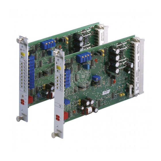
Analog amplifier card RE 30110/05.12 1/10 replaces: 05.11 Type VT-VSPA2-1-2X/… H/A/D 6641/00 Table of contents Features Contents Page – Suitable for controlling valve types 4WRA nominal sizes 6 and 10…2X, WRZ…7X and 3DREP…2X Features – Built-up in the form of a board in the Euro-format Ordering details, accessories 100 x 160 mm and is suitable for mounting into a rack Function... -
Page 3: Ordering Details, Accessories
2/10 Bosch Rexroth AG Hydraulics VSPA2-1-2X RE 30110/05.12 Ordering details VT-VSPA2 1 2X V0 Analog amplifier in Eurocard format Further details in clear text For controlling valve types: T1 = With one ramp time 4WRA 6…2X; 4WRA 10…2X; 4WRZ…7X, 3DREP…2X = 1... -
Page 4: Function
3/10 RE 30110/05.12 VSPA2-1-2X Hydraulics Bosch Rexroth AG Function Power supply [1] Enable function [8] With the enable function the current output stages are re- The amplifier card has a power supply with an inrush current leased and the internal command value signal is switched to limiter. - Page 5 4/10 Bosch Rexroth AG Hydraulics VSPA2-1-2X RE 30110/05.12 Block circuit diagram / connection allocation; VT-VSPA2-1-2X/V0/T1...
- Page 6 5/10 RE 30110/05.12 VSPA2-1-2X Hydraulics Bosch Rexroth AG Block circuit diagram / connection allocation; VT-VSPA2-1-2X/V0/T5...
- Page 7 6/10 Bosch Rexroth AG Hydraulics VSPA2-1-2X RE 30110/05.12 Technical data (for applications outside these parameters, please consult us!) Operating voltage 24 VDC + 40% – 20% Functional range: – Upper limiting value 35 V – Lower limiting value 18 V Power consumption <...
-
Page 8: Technical Data 6 And
7/10 RE 30110/05.12 VSPA2-1-2X Hydraulics Bosch Rexroth AG Technical data (continued) Clock frequency – WRA6 f 300 to 370 Hz (at 24 V U and 0 V U = 370 Hz) com. – WRA10 f 180 to 410 Hz (at 24 V U... - Page 9 8/10 Bosch Rexroth AG Hydraulics VSPA2-1-2X RE 30110/05.12 Display / adjustment element T1 J3 ramp time J8, J9 jump height J4 Jump function J1 inversion 0.2 to 50 sec. 4WRA6 and 10…2X Inverted • • • • 0.02 to 5 sec.
- Page 10 9/10 RE 30110/05.12 VSPA2-1-2X Hydraulics Bosch Rexroth AG Display / adjustment element T5 J3 ramp time J4 jump function J1 inversion J8, J9 jump height 0.2 to 50 sec. 4WRA6 and 10…2X Inverted • • • • 0.02 to 5 sec.
-
Page 11: Unit Dimension
© This document, as well as the data, specifications and other informa- Hydraulics tion set forth in it, are the exclusive property of Bosch Rexroth AG. It Zum Eisengießer 1 may not be reproduced or given to third parties without its consent. - Page 12 © This document, as well as the data, specifications and other informa- Hydraulics tion set forth in it, are the exclusive property of Bosch Rexroth AG. It Zum Eisengießer 1 may not be reproduced or given to third parties without its consent.
- Page 13 © This document, as well as the data, specifications and other informa- Hydraulics tion set forth in it, are the exclusive property of Bosch Rexroth AG. It Zum Eisengießer 1 may not be reproduced or given to third parties without its consent.
-
Page 14: Replaces
VT-VSPA2-1-2X/V0/T. Analog amplifier card component series 2X Operating instructions Replaces: 10.10 RE 30110-B/11.12 English <Fill this space with our product fig- ure>... - Page 15 © This document, as well as the data, specifica- tions and other information set forth in it, are the exclusive property of Bosch Rexroth AG. It may not be reproduced or given to third parties without its consent.
- Page 16 5.2.10 Clock generator [13] 5.2.11 Measuring sockets Transport and storage Storing the VT-VSPA2-1-2X Installation Work steps Safety regulations Installation conditions Unpacking the amplifier card Installing the amplifier card Commissioning Safety regulations Setting the amplifier card RE 30110-B/11.2012, VT-VSPA2-1-2X/V0/T., Bosch Rexroth AG...
- Page 17 Return to Bosch Rexroth AG 11.3 Packaging 11.4 Materials used 11.5 Recycling Extension and modification Troubleshooting 13.1 How to proceed for troubleshooting Technical data Appendix 15.1 List of addresses 15.1.1 Contacts for repairs and support Alphabetical index Bosch Rexroth AG, VT-VSPA2-1-2X/V0/T., RE 30110-B/11.2012...
-
Page 18: About This Documentation
The measures described for preventing these hazards must be observed. Safety instructions are set out as follows: RE 30110-B/11.2012, VT-VSPA2-1-2X/V0/T., Bosch Rexroth AG... -
Page 19: Symbols
The numbers indicate that the steps must be carried out one after the other. 1.3.3 Designations The following designations are used in this documentation: Table 4: Designations Designation Meaning Operating voltage VT-VSPA2 Analog amplifier card Bosch Rexroth AG, VT-VSPA2-1-2X/V0/T., RE 30110-B/11.2012... -
Page 20: Abbreviations
2.3 Improper use Any use deviating from the intended use is improper and thus not admissible. Bosch Rexroth AG does not assume any liability for damage caused by improper use. The user assumes all risks involved with improper use. The following cases of foreseeable misuse are also regarded as being improper: •... -
Page 21: Qualification Of Personnel
• in particular completely understanding the correlations regarding the safety equip- ment and • having knowledge of the function and set-up of hydraulic components. Bosch Rexroth offers measures supporting the training in specific fields. An overview of the training contents is available on the Internet via the following link: http://www.boschrexroth.de/didactic. -
Page 22: Product-Specific Safety Instructions
You may therefore only use the product within the IP protection class and envi- ronment specified in the data sheet. High pressure! Risk of injury! ▶ Depressurize the relevant part of the system before performing any work on the control electronics. RE 30110-B/11.2012, VT-VSPA2-1-2X/V0/T., Bosch Rexroth AG... - Page 23 The environment must be free from electrically conductive contamination (acids, bases, corrosive agents, salts, metal vapors, etc.) and the device must not be exposed to these substances. Rule out any deposits according to protection class IP. Bosch Rexroth AG, VT-VSPA2-1-2X/V0/T., RE 30110-B/11.2012...
-
Page 24: General Information On Damage To Property And Damage To The Product
▶ Handle the amplifier card with care. Do not touch exposed connection pins and sensitive electronic components. ▶ Transport and store the amplifier card carefully in the original packaging intend- ed for this purpose. RE 30110-B/11.2012, VT-VSPA2-1-2X/V0/T., Bosch Rexroth AG... -
Page 25: Scope Of Delivery
See below. 4.1 Recommended accessories Denomination Material number Closed card holder VT 12302 with use of a blind plate R900021004 Open card holder VT 3002-2X/48F R900020154 Bosch Rexroth AG, VT-VSPA2-1-2X/V0/T., RE 30110-B/11.2012... -
Page 26: Information On This Product
• "Ramp on/off" input • "Ready for operation" output signal • Switchable measuring socket (option T5) • Reverse polarity protection for the voltage supply • Power supply with DC/DC converter without raised zero point RE 30110-B/11.2012, VT-VSPA2-1-2X/V0/T., Bosch Rexroth AG... -
Page 27: Block Diagrams/Pin Assignments Of The Amplifier Card
14/40 Information on this product 5.2.1 Block diagrams/pin assignments of the amplifier card Fig. 1: Block diagrams/pin assignments of the amplifier card VT-VSPA../T1 Bosch Rexroth AG, VT-VSPA2-1-2X/V0/T., RE 30110-B/11.2012... - Page 28 Information on this product 15/40 Fig. 2: Block diagrams/pin assignments of the amplifier card VT-VSPA../T5 RE 30110-B/11.2012, VT-VSPA2-1-2X/V0/T., Bosch Rexroth AG...
-
Page 29: Setting And Display Elements Of The Amplifier Card Vt-Vspa../T1
Command value 2 Step level for positive direction Command value 3 S– Step level for negative direction Command value 4 Clock frequency output stage Ramp time The warranty expires if the sealed potentiometer is adjusted. Bosch Rexroth AG, VT-VSPA2-1-2X/V0/T., RE 30110-B/11.2012... -
Page 30: Setting And Display Elements Of The Amplifier Card Vt-Vspa../T5
Step level for negative direction Command value 4 Clock frequency output stage Ramp time 1 Ramp time 2 Ramp time 3 Ramp time 4 Ramp time 5 The warranty expires if the sealed potentiometer is adjusted. RE 30110-B/11.2012, VT-VSPA2-1-2X/V0/T., Bosch Rexroth AG... -
Page 31: Description Of The Functions And Components Of The Analog Amplifier Card
Only one call-up can be operated at the same time. If several call-ups are operated simultaneously, call-up "1" has the lowest priority and call-up "4" has the high- est priority. The respective active call-up is indicated via a yellow LED on the front plate. Bosch Rexroth AG, VT-VSPA2-1-2X/V0/T., RE 30110-B/11.2012... - Page 32 Adjustment options You can use jumper "J3" to select the possible setting range of the ramp time: 0.02 - 5 sec. or 0.2 - 50 sec. • The following applies to the amplifier card VT-VSPA2.../T5: RE 30110-B/11.2012, VT-VSPA2-1-2X/V0/T., Bosch Rexroth AG...
-
Page 33: Ramp On/Off
If both measures are set simultaneously, they cancel each other out. If the jumper (J2) is plugged, the 24 V input functions as ramp "on" input. If the ramp is active, this is indicated by an LED "T". Bosch Rexroth AG, VT-VSPA2-1-2X/V0/T., RE 30110-B/11.2012... -
Page 34: Ramp Time Selection Logic [19] (Only For Vt-Vspa2
To control the 4WRA-2X valves, the jumpers J7, J8 and J9 must be unplugged. Adjustment options • You can use the jumper "J4" to switch the step function on (J4 = open) or off (J4 = closed). RE 30110-B/11.2012, VT-VSPA2-1-2X/V0/T., Bosch Rexroth AG... -
Page 35: Amplitude Limiter [11]
A measuring socket for the command value (w) and the actual current value (I) is installed on the front plate. The following applies: Command value ±100 % = ±10 V Actual value ±100 % = ±2.5 V Bosch Rexroth AG, VT-VSPA2-1-2X/V0/T., RE 30110-B/11.2012... -
Page 36: Transport And Storage
5 °C to 40 °C and ensure a relative air humidity of 0 % to 65 %. ▶ Protect the amplifier card from dust, humidity and direct sunlight (100 % UV protection). ▶ Additional ozone formation or condensation close to the storage area must be prevented. RE 30110-B/11.2012, VT-VSPA2-1-2X/V0/T., Bosch Rexroth AG... -
Page 37: Installation
7.1 work steps Perform the steps in the following order: Plug jumper Install card Set command value Set command value zero point Set ramp times (internal/external) Set step level Set maximum values Bosch Rexroth AG, VT-VSPA2-1-2X/V0/T., RE 30110-B/11.2012... -
Page 38: Safety Regulations
• Electric signals taken out via control electronics (e. g. the "ready for operation" signal) must not be used for switching safety-relevant machine functions. (See also EN ISO 13849 "Safety of machinery - safety-related parts of control systems"). RE 30110-B/11.2012, VT-VSPA2-1-2X/V0/T., Bosch Rexroth AG... -
Page 39: Unpacking The Amplifier Card
Here, interference is eliminated which is transported to the control electronics via the data and supply voltage lines. This function is only ensured if the system earth itself does not introduce interference into the control electronics. Bosch Rexroth recommends screening the solenoid lines as well. - Page 40 Measuring point signal Reserved Reference/ramp external Reference potential for outputs (M0) Reserved Command value output ±10 V –10 V/25 mA Operating voltage (24 V) Actual value output ±10 V +10 V/25 mA L0 (0 V) RE 30110-B/11.2012, VT-VSPA2-1-2X/V0/T., Bosch Rexroth AG...
-
Page 41: Commissioning
Set internal command value to 0 V using the potentiometer "Zw". Check the set- ting of the measuring socket "w". option VT-.../T5 Procedure: Prerequisite: No command value call-up must be operated. Set external command value specifications to 0 V. Bosch Rexroth AG, VT-VSPA2-1-2X/V0/T., RE 30110-B/11.2012... -
Page 42: Setting The Command Value
Set the ramp time using the associated potentiometer (t1 to t5) according to the conversion formula or conversion table. Check the setting of the measuring socket "v". You can now set the next ramp time (repeat procedure). RE 30110-B/11.2012, VT-VSPA2-1-2X/V0/T., Bosch Rexroth AG... -
Page 43: Externally Setting The Ramp Time
Use potentiometer "S+" to set the required step level. Use potentiometer "Zw" to set the measurement signal to –0.3 V. Use potentiometer "S–" to set the required step level. Use potentiometer "Zw" to set the zero point. Bosch Rexroth AG, VT-VSPA2-1-2X/V0/T., RE 30110-B/11.2012... -
Page 44: Setting The Maximum Values
In the condition as supplied, the setting of the clock frequency corresponds to the requirements of the valve WRZ. Rotating the "f" potentiometer changes the valve hysteresis and may lead to disturbing noise developments. RE 30110-B/11.2012, VT-VSPA2-1-2X/V0/T., Bosch Rexroth AG... -
Page 45: Maintenance And Repair
VT-VSPA2-1-2X performed to one's own author- ity are not admissible! Repair and maintenance works may only be performed by Bosch Rexroth AG. For repair and maintenance works, send the device to the service address specified in chapter 15. -
Page 46: Disassembly And Exchange
Proceed as follows in order to prepare the VT-VSPA2-1-2X amplifier card for storage and further use: ▶ Only use the original packaging for storage. ▶ Comply with the admissible storage temperature range specified in RE 30110. ▶ Protect the amplifier card from dust and humidity. RE 30110-B/11.2012, VT-VSPA2-1-2X/V0/T., Bosch Rexroth AG... -
Page 47: Disposal
Thus, dispose of the VT-VSPA2-1-2X amplifier card and the packaging material in accordance with the currently applicable national regulations in your country. 11.2 Return to Bosch Rexroth AG The products manufactured by us can be returned to us for disposal purposes at no costs. -
Page 48: Extension And Modification
– Try to get a clear idea of the cause of the error. Ask the direct (machine) operator. – If you could not remedy the occurred error, please contact one of the addresses you find at www.boschrexroth.com or in the list of addresses in the appendix. RE 30110-B/11.2012, VT-VSPA2-1-2X/V0/T., Bosch Rexroth AG... -
Page 49: Technical Data
> 100 kΩ 0 to 6.5 V → OFF; R > 100 kΩ Ramp on/off 8.5 V to U → ON; R > 100 kΩ 0 to 6.5 V → OFF; R > 100 kΩ Bosch Rexroth AG, VT-VSPA2-1-2X/V0/T., RE 30110-B/11.2012... -
Page 50: Appendix
15.1 list of addresses 15.1.1 Contacts for repairs and support Bosch Rexroth AG Service Industriehydraulik [Industrial hydraulics] Bgm.-Dr.-Nebel-Straße 8 97816 Lohr am Main Germany Phone +49 (0) 9352 40 50 60 http://www.boschrexroth.com/service Email: service@boschrexroth.de RE 30110-B/11.2012, VT-VSPA2-1-2X/V0/T., Bosch Rexroth AG... -
Page 51: Alphabetical Index
– Command value – Safety regulations – Command value zero point – Work steps – Maximum values Installation conditions – Ramp time Intended use – Step level Setting the amplifier card Setting the command value Bosch Rexroth AG, VT-VSPA2-1-2X/V0/T., RE 30110-B/11.2012... - Page 52 Setting the maximum values Setting the ramp time – externally Setting the step level Specification of the inputs Specification of the outputs Storage Symbols ▶ T Technical data Transport Troubleshooting ▶ U Unpacking ▶ w Warranty RE 30110-B/11.2012, VT-VSPA2-1-2X/V0/T., Bosch Rexroth AG...
- Page 53 Bosch Rexroth AG Zum Eisengießer 1 97816 Lohr am Main Germany Phone +49 (0) 9352 18-0 info@boschrexroth.de www.boschrexroth.com Subject to change without notice Printed in Germany RE 30110-B, 11.2012...
- Page 54 Analog amplifier card RE 30110-Z/10.12 1/10 Replace: 12.11 Type VT-VSPA2-1-2X/V0/T1 Type VT-VSPA2-1-2X/V0/T5 Additional information Information regarding the conversion of different ampli- fier cards to amplifier card type VT-VSPA2-1-2X/V0/T1 Material number R901002090 and amplifier card type VT-VSPA2-1-2X/V0/T5 Material number R901002095 HAD6641 Considering the prerequisites mentioned in this additional information, the analog amplifier cards type VT-VSPA2-1-2X/V0/T1 and VT-VSPA2-1-2X/V0/T5 can be used as replacement for the following amplifier modules: VT-VSPA2-1-2X/V0/T1 as replacement for:...
- Page 55 2/10 Bosch Rexroth AG Hydraulics Additional information RE 30110-Z/10.12 Configurations for VT-VSPA2-1-2X/V0/...
- Page 56 3/10 RE 30110-Z/10.12 Additional information Hydraulics Bosch Rexroth AG Pre-settings The following pre-settings must be made before the exact ad- • VT-VSPA2-1-2X/V0/T1 serves as replacement for: justment of VT-VSPA2-1-2X/V0/T1 or T5: VT 3000, VT 3013, VT 3014, VT 3026, • Exchange the card holder:...
- Page 57 4/10 Bosch Rexroth AG Hydraulics Additional information RE 30110-Z/10.12 Block diagram / pinout VT 3000, VT 3013, VT 3014, VT 3026...
- Page 58 5/10 RE 30110-Z/10.12 Additional information Hydraulics Bosch Rexroth AG Block diagram / pinout VT 3006, VT 3017, VT 3018...
- Page 59 6/10 Bosch Rexroth AG Hydraulics Additional information RE 30110-Z/10.12 Block diagram / pinout VT-VSPA2-1-1X/T1...
- Page 60 7/10 RE 30110-Z/10.12 Additional information Hydraulics Bosch Rexroth AG Block diagram / pinout VT-VSPA2-1-1X/T5...
- Page 61 8/10 Bosch Rexroth AG Hydraulics Additional information RE 30110-Z/10.12 Block diagram / pinout VT-VSPA2-50-1X/T1...
- Page 62 9/10 RE 30110-Z/10.12 Additional information Hydraulics Bosch Rexroth AG Block diagram / pinout VT-VSPA2-50-1X/T5...
- Page 63 © This document, as well as the data, specifications and other informa- Hydraulics tion set forth in it, are the exclusive property of Bosch Rexroth AG. It Zum Eisengießer 1 may not be reproduced or given to third parties without its consent.
- Page 64 © This document, as well as the data, specifications and other informa- Hydraulics tion set forth in it, are the exclusive property of Bosch Rexroth AG. It Zum Eisengießer 1 may not be reproduced or given to third parties without its consent.
- Page 65 © This document, as well as the data, specifications and other informa- Hydraulics tion set forth in it, are the exclusive property of Bosch Rexroth AG. It Zum Eisengießer 1 may not be reproduced or given to third parties without its consent.