
Related Manuals for Dell PowerConnect J-SRX210


Summary of Contents for Dell PowerConnect J-SRX210
- Page 1 Dell™ PowerConnect™ J-Series J-SRX210 Services Gateway Hardware Guide Published: 2010-06-16...
- Page 2 Information in this document is subject to change without notice. All rights reserved. Reproduction of these materials in any manner whatsoever without the written permission of Dell, Inc. is strictly forbidden. Trademarks used in this text: Dell, the DELL logo, and PowerConnect are trademarks of Dell Inc.
- Page 3 END USER LICENSE AGREEMENT READ THIS END USER LICENSE AGREEMENT (“AGREEMENT”) BEFORE DOWNLOADING, INSTALLING, OR USING THE SOFTWARE. BY DOWNLOADING, INSTALLING, OR USING THE SOFTWARE OR OTHERWISE EXPRESSING YOUR AGREEMENT TO THE TERMS CONTAINED HEREIN, YOU (AS CUSTOMER OR IF YOU ARE NOT THE CUSTOMER, AS A REPRESENTATIVE/AGENT AUTHORIZED TO BIND THE CUSTOMER) CONSENT TO BE BOUND BY THIS AGREEMENT.
- Page 4 Software in any manner that extends or is broader than the uses purchased by Customer from Juniper or an authorized Juniper reseller; (i) use Embedded Software on non-Juniper equipment; (j) use Embedded Software (or make it available for use) on Juniper equipment that the Customer did not originally purchase from Juniper or an authorized Juniper reseller;...
- Page 5 12. Commercial Computer Software. The Software is “commercial computer software” and is provided with restricted rights. Use, duplication, or disclosure by the United States government is subject to restrictions set forth in this Agreement and as provided in DFARS 227.7201 through 227.7202-4, FAR 12.212, FAR 27.405(b)(2), FAR 52.227-19, or FAR 52.227-14(ALT III) as applicable. 13.
-
Page 7: Table Of Contents
Table of Contents About This Guide ..........xiii Objectives . - Page 8 PowerConnect J-SRX210 Services Gateway Hardware Guide Chapter 3 J-SRX210 Services Gateway 3G ExpressCard ......25 J-SRX210 Services Gateway 3G ExpressCard Overview ..... 25 Introduction .
- Page 9 Table of Contents Chapter 10 Unpacking the J-SRX210 Services Gateway ......57 Unpacking the J-SRX210 Services Gateway ......57 Verifying Parts Received with the J-SRX210 Services Gateway .
- Page 10 Dell Support ........
- Page 11 Support Service ..........153 Dell Enterprise Training and Certification ....... . 153 Problems With Your Order .
- Page 12 PowerConnect J-SRX210 Services Gateway Hardware Guide...
-
Page 13: About This Guide
About This Guide This preface includes the following topics: Objectives on page xiii Audience on page xiii Documentation Conventions on page xiv Repair and Warranty on page xv Requesting Technical Support on page xv Objectives This guide describes hardware components and installation, basic configuration, and basic troubleshooting procedures for the PowerConnect J-Series J-SRX210 Services Gateway. -
Page 14: Documentation Conventions
PowerConnect J-SRX210 Services Gateway Hardware Guide Documentation Conventions Table 1: Notice Icons Icon Meaning Description Informational note Indicates important features or instructions. Caution Indicates a situation that might result in loss of data or hardware damage. Warning Alerts you to the risk of personal injury or death. -
Page 15: Repair And Warranty
Damage due to servicing that is not authorized by Dell is not covered by your warranty. Read and follow the safety instructions that came with the product. - Page 16 PowerConnect J-SRX210 Services Gateway Hardware Guide...
-
Page 17: J-Srx210 Services Gateway Overview
PART 1 J-SRX210 Services Gateway Overview Introduction to the J-SRX210 Services Gateway on page 3 J-SRX210 Services Gateway Hardware Components and Specifications on page 7 J-SRX210 Services Gateway 3G ExpressCard on page 25 J-SRX210 Services Gateway Power over Ethernet Support on page 31 J-SRX210 Services Gateway with Integrated Convergence Services on page 35 J-SRX210 Services Gateway Mini-Physical Interface Modules on page 41... - Page 18 PowerConnect J-SRX210 Services Gateway Hardware Guide...
-
Page 19: Introduction To The J-Srx210 Services Gateway
CHAPTER 1 Introduction to the J-SRX210 Services Gateway This chapter includes the following topics: J-SRX210 Services Gateway Description on page 3 J-SRX210 Services Gateway Hardware Features on page 4 J-SRX210 Services Gateway Description This topic includes the following sections: About the J-SRX210 Services Gateway on page 3 J-SRX210 Services Gateway Models on page 3 Accessing the J-SRX210 Services Gateway on page 4 About the J-SRX210 Services Gateway... -
Page 20: Accessing The J-Srx210 Services Gateway
PowerConnect J-SRX210 Services Gateway Hardware Guide Table 3: J-SRX210 Services Gateway Models (continued) Product Name Device Type Model Number J-SRX210 Services Gateway Power over Ethernet (PoE) J-SRX210H-POE with PoE J-SRX210 Services Gateway Voice J-SRX210H-P-MGW with integrated convergence services All J-SRX210 Services Gateways run the JUNOS operating system. - Page 21 Chapter 1: Introduction to the J-SRX210 Services Gateway Table 4: J-SRX210 Services Gateway Hardware Features (continued) J-SRX210 Services J-SRX210 J-SRX210 J-SRX210 Gateway with Services Services Services Integrated Gateway Low Gateway High Gateway Power Convergence Feature Memory Memory over Ethernet Services Power supply 60 watts 60 watts...
- Page 22 PowerConnect J-SRX210 Services Gateway Hardware Guide J-SRX210 Services Gateway Specifications on page 7...
-
Page 23: Specifications
CHAPTER 2 J-SRX210 Services Gateway Hardware Components and Specifications This chapter includes the following topics: J-SRX210 Services Gateway Specifications on page 7 J-SRX210 Services Gateway Front Panel and Back Panel Views (Low Memory, High Memory and PoE Version) on page 9 J-SRX210 Services Gateway with Integrated Convergence Services Front Panel and Back Panel Views on page 12 J-SRX210 Services Gateway Built-In Interfaces on page 14... -
Page 24: J-Srx210 Services Gateway Specifications
PowerConnect J-SRX210 Services Gateway Hardware Guide Figure 1: J-SRX210 Services Gateway with Integrated Convergence Services Figure 2 on page 8 shows the J-SRX210 Services Gateway chassis (for low memory and high memory model). Figure 2: J-SRX210 Services Gateway Table 5 on page 8 provides information on the physical specifications of the device. -
Page 25: J-Srx210 Services Gateway Front Panel And Back Panel Views (Low Memory, High Memory And Poe Version)
Chapter 2: J-SRX210 Services Gateway Hardware Components and Specifications Table 5: J-SRX210 Services Gateway Specifications (continued) Specification Value Altitude No performance degradation up to 10,000 ft (3048 m) for J-SRX210 Services Gateway Low Memory, High Memory, and PoE models No performance degradation up to 6561 ft (2000 m) for J-SRX210 Services Gateway with Integrated Convergence Services) Temperature... -
Page 26: J-Srx210 Services Gateway Front Panel
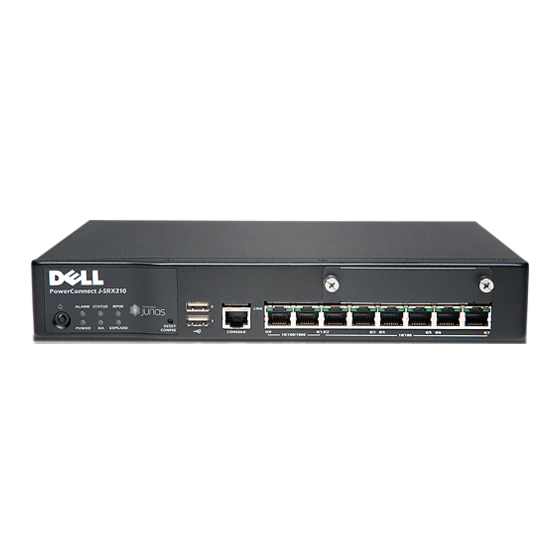
PowerConnect J-SRX210 Services Gateway Hardware Guide J-SRX210 Services Gateway Front Panel Figure 3 on page 10 shows the front panel of the J-SRX210 Services Gateway. Figure 3: J-SRX210 Services Gateway Front Panel J-SRX210 Table 6 on page 10 lists the front panel components of the services gateway. - Page 27 Chapter 2: J-SRX210 Services Gateway Hardware Components and Specifications Figure 4: J-SRX210 Services Gateway Back Panel Table 7 on page 11 lists the back panel components of the J-SRX210 Services Gateway. NOTE: The numbers in Figure 4 on page 11 correspond to the numbers in Table 7 on page 11.
-
Page 28: J-Srx210 Services Gateway With Integrated Convergence Services Front Panel And Back Panel Views
PowerConnect J-SRX210 Services Gateway Hardware Guide J-SRX210 Services Gateway with Integrated Convergence Services Front Panel and Back Panel Views This topic contains views of the front panel and back panel of the J-SRX210 Services Gateway with Integrated Convergence Services. This topic includes the following sections:... -
Page 29: Panel
Chapter 2: J-SRX210 Services Gateway Hardware Components and Specifications Table 8: J-SRX210 Services Gateway with Integrated Convergence Services Front Panel Components (continued) Number Component Universal Serial Bus (USB) ports Console port Gigabit Ethernet ports and Fast Ethernet ports J-SRX210 Services Gateway with Integrated Convergence Services Back Panel Figure 6 on page 13 illustrates the back panel of the J-SRX210 Services Gateway with Integrated Convergence Services. -
Page 30: J-Srx210 Services Gateway Built-In Interfaces
PowerConnect J-SRX210 Services Gateway Hardware Guide J-SRX210 Services Gateway Built-In Interfaces on page 14 J-SRX210 Services Gateway LEDs on page 17 J-SRX210 Services Gateway Boot Devices on page 22 J-SRX210 Services Gateway Cooling System on page 22 J-SRX210 Services Gateway Power Supply on page 24... - Page 31 Also, the USB device must have JUNOS installed. To provide the USB interfaces that are used to communicate with many types of USB storage devices compatible with JUNOS Software. Contact your Dell customer service representative for more information.
- Page 32 PowerConnect J-SRX210 Services Gateway Hardware Guide Table 10: J-SRX210 Services Gateway Built-In Hardware Interfaces (continued) Interface Type Specifications Description Console Consists of one port The console port can be used as follows: Uses an RJ-45 serial cable connector To provide the console...
-
Page 33: J-Srx210 Services Gateway Leds
NOTE: We recommend the use of transceivers compatible with JUNOS Software on a J-SRX210 Services Gateway. Correct operation cannot be guaranteed if the transceivers are not compatible with JUNOS Software. Contact Dell for the correct transceiver part number for your device. - Page 34 PowerConnect J-SRX210 Services Gateway Hardware Guide Table 11: J-SRX210 Services Gateway Front Panel Components LEDs Component Description Usage Alarm LED The Alarm LED has the following indicator colors: The Alarm LED can be used to gather Red and steadily on indicates a major alarm.
-
Page 35: Ethernet Port Leds
Chapter 2: J-SRX210 Services Gateway Hardware Components and Specifications Table 11: J-SRX210 Services Gateway Front Panel Components LEDs (continued) Component Description Usage The 3G ExpressCard LED has the following The 3G ExpressCard LED ExpressCardLED indicator colors: provides information on the functioning of the Green and steadily on indicates that the ExpressCard slot. -
Page 36: Voice Interface Port Led
PowerConnect J-SRX210 Services Gateway Hardware Guide NOTE: The numbers in Figure 8 on page 19 correspond to the numbers in Table 12 on page 20. Table 12 on page 20 describes the built-in Ethernet port LEDs. Table 12: J-SRX210 Services Gateway Built-In Ethernet Port LEDs... - Page 37 Chapter 2: J-SRX210 Services Gateway Hardware Components and Specifications Figure 9: J-SRX210 Services Gateway Voice Interface Port LEDs J-SRX210 Table 13 on page 21 describes the Voice Interface port LEDs. Table 13: J-SRX210 Services Gateway Voice Interface Port LEDs Color State Description Voice Interface...
-
Page 38: Scheme
PowerConnect J-SRX210 Services Gateway Hardware Guide J-SRX210 Services Gateway Boot Devices and Dual-Root Partitioning Scheme This topic includes the following sections: Boot Devices on page 22 Dual-Root Partitioning Scheme on page 22 Boot Devices The J-SRX210 Services Gateway can boot from two devices: Internal NAND flash (default;... - Page 39 Chapter 2: J-SRX210 Services Gateway Hardware Components and Specifications The cooling system works from side-to-rear in the services gateway chassis. The fans draw air through vents along the left and right sides of the chassis and exhaust the air through the rear side of the chassis. The airflow produced by the fans keeps device components within the acceptable temperature range.
-
Page 40: J-Srx210 Services Gateway Power Supply
J-SRX210 Services Gateway Power Supply The power supply for the J-SRX210 Services Gateway is external. You must use the power supply adapter provided by Dell to provide power to the services gateway. Related Topics J-SRX210 Services Gateway Specifications on page 7... -
Page 41: J-Srx210 Services Gateway 3G Expresscard
CHAPTER 3 J-SRX210 Services Gateway 3G ExpressCard This chapter includes the following topics: J-SRX210 Services Gateway 3G ExpressCard Overview on page 25 Installing the 3G ExpressCard in the J-SRX210 Services Gateway ExpressCard Slot on page 27 J-SRX210 Services Gateway 3G ExpressCard Basic CLI Commands on page 28 J-SRX210 Services Gateway 3G ExpressCard Overview This topic provides an overview of the J-SRX210 Services Gateway 3G ExpressCard and it includes the following sections:... -
Page 42: Key Features
PowerConnect J-SRX210 Services Gateway Hardware Guide To use the ExpressCard, you plug it into the 3G ExpressCard slot, enabling you to dial a wireless call to the 3G wireless service provider network, which acts as an Internet gateway. To use the 3G ExpressCard as a backup interface, you can use the dialer feature available in the services gateway. -
Page 43: Physical Specifications
Installing the 3G ExpressCard in the J-SRX210 Services Gateway ExpressCard Slot TIP: Placing the J-SRX210 Services Gateway on a flat, level surface, with the Dell logo facing up, will make it easier to align and insert the 3G ExpressCard in the ExpressCard slot. -
Page 44: J-Srx210 Services Gateway 3G Expresscard Basic Cli Commands
PowerConnect J-SRX210 Services Gateway Hardware Guide Ensure that the 3G ExpressCard is parallel with the surface on which the J-SRX210 Services Gateway is placed. Ensure that the center of the 3G ExpressCard is aligned with the center of the ExpressCard slot on the J-SRX210 Services Gateway. - Page 45 Chapter 3: J-SRX210 Services Gateway 3G ExpressCard Table 15: J-SRX210 Services Gateway 3G ExpressCard Basic CLI Commands Action Command Checks the status of the 3G ExpressCard. show modem wireless interface cl-0/0/8 show interfaces terse CDMA ExpressCards Activates the CDMA ExpressCard request modem wireless activate IOTA —...
- Page 46 PowerConnect J-SRX210 Services Gateway Hardware Guide...
-
Page 47: J-Srx210 Services Gateway Power Over Ethernet Support
CHAPTER 4 J-SRX210 Services Gateway Power over Ethernet Support This chapter includes the following topics: J-SRX210 Services Gateway PoE Overview on page 31 Configuring PoE Functionality on the J-SRX210 Services Gateway on page 33 J-SRX210 Services Gateway PoE Overview This topic includes the following sections: Introduction on page 31 PoE Classes and Power Ratings on page 32 Introduction... -
Page 48: Poe Classes And Power Ratings
PowerConnect J-SRX210 Services Gateway Hardware Guide Table 16: J-SRX210 Services Gateway PoE Specifications (continued) Power Management Schemes Values Supported ports The following ports support PoE: ge-0/0/0 ge-0/0/1 fe-0/0/2 fe-0/0/3 Total PoE power sourcing capacity 50 watts Per-port power limit 30 watts... -
Page 49: Configuring Poe Functionality On The J-Srx210 Services Gateway
Chapter 4: J-SRX210 Services Gateway Power over Ethernet Support Related Topics J-SRX210 Services Gateway Description on page 3 J-SRX210 Services Gateway Specifications on page 7 J-SRX210 Services Gateway Front Panel and Back Panel Views on page 9 J-SRX210 Services Gateway Built-In Interfaces on page 14 J-SRX210 Services Gateway LEDs on page 17 Mini-Physical Interface Modules on the J-SRX210 Services Gateway J-SRX210 Services Gateway 3G ExpressCard Overview on page 25... - Page 50 PowerConnect J-SRX210 Services Gateway Hardware Guide...
-
Page 51: J-Srx210 Services Gateway With Integrated Convergence Services
CHAPTER 5 J-SRX210 Services Gateway with Integrated Convergence Services This chapter includes the following topics: About the J-SRX210 Services Gateway with Integrated Convergence Services on page 35 Understanding the Functions of the J-SRX210 Services Gateway with Integrated Convergence Services on page 37 J-SRX210 Services Gateway with Integrated Convergence Services Interoperability on page 38 Configuring the J-SRX210 Services Gateway with Integrated Convergence... -
Page 52: Basic Functions
PowerConnect J-SRX210 Services Gateway Hardware Guide Basic Functions The availability of hardware and software for voice and data transmission on the same device is called integrated convergence services. J-SRX210 Services Gateway with Integrated Convergence Services implements a media gateway and a survivable call server. The J-SRX210 Services Gateway with Integrated... -
Page 53: Common Deployment Scenarios
Chapter 5: J-SRX210 Services Gateway with Integrated Convergence Services Common Deployment Scenarios The J-SRX210 Services Gateway with Integrated Convergence Services is deployed in following environments: Enterprises that deploy VoIP in their headquarters and want to enable VoIP functionality for their branch offices. Services providers (SPs) who provide VoIP services to their business customers. -
Page 54: J-Srx210 Services Gateway With Integrated Convergence Services Interoperability
PowerConnect J-SRX210 Services Gateway Hardware Guide NOTE: The 2-Port FXS/2-Port FXO Mini-PIM and the 4-Port FXO Mini-PIM do not support failover relay between any of the FXS and FXO ports. Telephony interface expansion available through Mini-PIM interface card option includes a 2–Port FXS/2–Port FXO Mini-PIM, 4–Port FXO Mini-PIM, and an IP Flex T1/E1 Mini-PIM... -
Page 55: Services
Chapter 5: J-SRX210 Services Gateway with Integrated Convergence Services Table 18: J-SRX210 Services Gateway Integrated Convergence Services Interoperability (continued) Phone Types Devices SIP call servers Avaya CM 5.2 with SES Avaya ASM (Aura 1.x) Microsoft OCS R1 and R2 Asterisk 1.6.x (Open Source) Related Topics About the J-SRX210 Services Gateway with Integrated Convergence Services on page 35 Understanding the functions of the J-SRX210 Services Gateway with Integrated... - Page 56 PowerConnect J-SRX210 Services Gateway Hardware Guide...
-
Page 57: J-Srx210 Services Gateway Mini-Physical Interface Modules
CHAPTER 6 J-SRX210 Services Gateway Mini-Physical Interface Modules This chapter includes the following topic: J-SRX210 Services Gateway Mini-Physical Interface Modules on page 41 J-SRX210 Services Gateway Mini-Physical Interface Modules The J-SRX210 Services Gateway supports Mini-Physical Interface Modules (Mini-PIMs). A Mini-PIM is a network interface card that is installed on the services gateway to provide physical connections to a LAN or a WAN. - Page 58 PowerConnect J-SRX210 Services Gateway Hardware Guide...
-
Page 59: Setting Up The J-Srx210 Services Gateway
PART 2 Setting Up the J-SRX210 Services Gateway Preparing the Site for the J-SRX210 Services Gateway Installation on page 45 Installation Overview for the J-SRX210 Services Gateway on page 53 Required Tools and Parts for Installing and Maintaining the J-SRX210 Services Gateway on page 55 Unpacking the J-SRX210 Services Gateway on page 57 Preparing the J-SRX210 Services Gateway for Installation on page 61... - Page 60 PowerConnect J-SRX210 Services Gateway Hardware Guide...
-
Page 61: Preparing The Site For The J-Srx210 Services Gateway Installation
CHAPTER 7 Preparing the Site for the J-SRX210 Services Gateway Installation This chapter provides a checklist to help you prepare your site for installation of the J-SRX210 Services Gateway. Read this section to make sure that your site has the proper operating environment and equipment. - Page 62 PowerConnect J-SRX210 Services Gateway Hardware Guide Table 19: Site Preparation Checklist for the J-SRX210 Services Gateway Installation (continued) Performed Item or Task Additional Information Date Notes Measure distance between “J-SRX210 Services external power sources and Gateway Site Electrical device installation site.
-
Page 63: General Site Guidelines For Installing The J-Srx210 Services Gateway
Chapter 7: Preparing the Site for the J-SRX210 Services Gateway Installation Table 19: Site Preparation Checklist for the J-SRX210 Services Gateway Installation (continued) Performed Item or Task Additional Information Date Notes Acquire cables and connectors. “Interface Cable and Wire Specifications for the Review the maximum distance J-SRX210 Services allowed for each cable. -
Page 64: J-Srx210 Services Gateway Cabinet Requirements
PowerConnect J-SRX210 Services Gateway Hardware Guide J-SRX210 Services Gateway Rack Requirements on page 49 Site Preparation Checklist for the J-SRX210 Services Gateway on page 45 Clearance Requirements for Airflow and Hardware Maintenance of the J-SRX210 Services Gateway on page 50 J-SRX210 Services Gateway Cabinet Requirements The J-SRX210 Services Gateway can be installed in a standard 800 mm (31.5 in.) or larger... -
Page 65: J-Srx210 Services Gateway Rack Requirements
Chapter 7: Preparing the Site for the J-SRX210 Services Gateway Installation Clearance Requirements for Airflow and Hardware Maintenance of the J-SRX210 Services Gateway on page 50 J-SRX210 Services Gateway Rack Requirements The services gateway can be installed in a rack. Many types of racks are acceptable, including front-mount racks and four-post (telco) racks. -
Page 66: Clearance Requirements For Airflow And Hardware Maintenance Of The J-Srx210
PowerConnect J-SRX210 Services Gateway Hardware Guide Clearance Requirements for Airflow and Hardware Maintenance of the J-SRX210 Services Gateway When planning the installation site for the J-SRX210 Services Gateway, you need to allow sufficient clearance around the rack or cabinet where you are planning to install the device. -
Page 67: J-Srx210 Services Gateway Electrical And Power Requirements
Chapter 7: Preparing the Site for the J-SRX210 Services Gateway Installation J-SRX210 Services Gateway Rack Requirements on page 49 J-SRX210 Services Gateway Electrical and Power Requirements There are factors you must consider while planning the electrical wiring and power availability at your site. These factors include the following requirements: Power specifications and requirements for the device Electrical wiring guidelines for the device installation site Power, connection, and power cord specifications for the device... - Page 68 PowerConnect J-SRX210 Services Gateway Hardware Guide...
-
Page 69: Installation Overview For The J-Srx210 Services Gateway
CHAPTER 8 Installation Overview for the J-SRX210 Services Gateway This chapter includes the following topic: Installation Overview for the J-SRX210 Services Gateway on page 53 Installation Overview for the J-SRX210 Services Gateway After you have prepared your installation site, you are ready to unpack and install the services gateway. - Page 70 PowerConnect J-SRX210 Services Gateway Hardware Guide Table 23: Installation Process Order for the J-SRX210 Services Gateway (continued) Step Task For more information, see Power on the services gateway. “Powering On and Powering Off the J-SRX210 Services Gateway” on page 78...
-
Page 71: Services Gateway
CHAPTER 9 Required Tools and Parts for Installing and Maintaining the J-SRX210 Services Gateway This chapter includes the following topic: Required Tools and Parts for Installing and Maintaining the J-SRX210 Services Gateway on page 55 Required Tools and Parts for Installing and Maintaining the J-SRX210 Services Gateway Table 24 on page 55 lists the tools and equipments required to install and maintain the J-SRX210 Services Gateway. - Page 72 PowerConnect J-SRX210 Services Gateway Hardware Guide J-SRX210 Services Gateway Installation on page 65 Grounding the J-SRX210 Services Gateway on page 77 Connecting the J-SRX210 Services Gateway to the Power Supply on page 75 Packing the J-SRX210 Services Gateway and Components for Shipment on page 157...
-
Page 73: Required Tools And Parts For Installing And Maintaining The J-Srx210
CHAPTER 10 Unpacking the J-SRX210 Services Gateway This chapter includes the following topics: Unpacking the J-SRX210 Services Gateway on page 57 Verifying Parts Received with the J-SRX210 Services Gateway on page 58 Unpacking the J-SRX210 Services Gateway The J-SRX210 Services Gateway is shipped in a cardboard carton. The carton also contains an accessory box and the J-SRX210 Services Gateway Quick Start Guide. -
Page 74: Verifying Parts Received With The J-Srx210 Services Gateway
The packing list specifies the part numbers and descriptions of each part in your order. If any part is missing, contact your Dell customer service representative. A fully configured J-SRX210 Services Gateway contains the chassis with installed components, listed in Table 25 on page 58, and an accessory box, which contains the parts listed in Table 26 on page 59. - Page 75 Services Gateway must be ordered separately. Contact your Dell customer service representative for more information. NOTE: The Mini-Physical Interface Modules (Mini-PIMs) are not shipped with the device. You have to order them separately. Contact your Dell customer service representative for more information. Related Topics...
- Page 76 PowerConnect J-SRX210 Services Gateway Hardware Guide...
-
Page 77: Preparing The J-Srx210 Services Gateway For Installation
Preparing the J-SRX210 Services Gateway for Wall-Mount Installation on page 64 The mounting kits for rack, wall, and desk installation of the J-SRX210 Services Gateway must be ordered separately. Contact your Dell customer service representative for more information. Related Topics... -
Page 78: Preparing The J-Srx210 Services Gateway For Rack-Mount Installation
PowerConnect J-SRX210 Services Gateway Hardware Guide Preparing the J-SRX210 Services Gateway for Rack-Mount Installation You can mount a J-SRX210 Services Gateway on four-post (telco) racks, enclosed cabinets, and open-frame racks. NOTE: The J-SRX210 Services Gateway does not support center-mount racks. -
Page 79: Preparing The J-Srx210 Services Gateway For Desk-Mount Installation
Chapter 11: Preparing the J-SRX210 Services Gateway for Installation Preparing the J-SRX210 Services Gateway for Rack-Mount, Desk-Mount, and Wall-Mount Installation on page 61 Preparing the J-SRX210 Services Gateway for Desk-Mount Installation on page 63 Preparing the J-SRX210 Services Gateway for Wall-Mount Installation on page 64 Preparing the J-SRX210 Services Gateway for Desk-Mount Installation You can mount a J-SRX210 Services Gateway on a desk or other level surface horizontally or vertically. -
Page 80: Preparing The J-Srx210 Services Gateway For Wall-Mount Installation
PowerConnect J-SRX210 Services Gateway Hardware Guide Preparing the J-SRX210 Services Gateway for Rack-Mount Installation on page 62 Preparing the J-SRX210 Services Gateway for Wall-Mount Installation on page 64 Preparing the J-SRX210 Services Gateway for Wall-Mount Installation You can mount a J-SRX210 Services Gateway on a wall. The four rubber feet attached to the chassis provide stability. -
Page 81: Installing The J-Srx210 Services Gateway
CHAPTER 12 Installing the J-SRX210 Services Gateway This chapter includes the following topics: J-SRX210 Services Gateway Safety Requirements, Warnings, and Guidelines on page 65 J-SRX210 Services Gateway Installation on page 65 Replacing or Installing Mini-Physical Interface Modules in the J-SRX210 Services Gateway on page 74 J-SRX210 Services Gateway Safety Requirements, Warnings, and Guidelines To avoid harm to yourself or the device as you install and maintain it, follow the guidelines... -
Page 82: Adjusting The Power Supply Adapter Tray For The J-Srx210 Services Gateway For Rack-Mount Installation
PowerConnect J-SRX210 Services Gateway Hardware Guide Install the device as appropriate for your site using one of the following procedures: Adjusting the Power Supply Adapter Tray for the J-SRX210 Services Gateway for Rack-Mount Installation on page 66 Installing the J-SRX210 Services Gateway in a Rack on page 67... -
Page 83: Installing The J-Srx210 Services Gateway In A Rack
Chapter 12: Installing the J-SRX210 Services Gateway Figure 13 on page 67 shows the adjustments to the power supply adapter tray required for the 150-watt power supply. Figure 13: Adjusting Power Supply Adapter Tray for 150 Watts Attaching the adapter stopper brackets into power supply adapter tray. Fully configured power supply adapter tray. - Page 84 PowerConnect J-SRX210 Services Gateway Hardware Guide To install the device in a rack: Position a mounting bracket on each side of the chassis as shown in Figure 14 on page 68. Figure 14: Installation of J-SRX210 Services Gateway in a Rack —...
- Page 85 Chapter 12: Installing the J-SRX210 Services Gateway Figure 16: J-SRX210 Services Gateway Rack Installation — Positioning Power Supply Adapter Tray Have one person grasp the sides of the device, lift it, and position it in the rack. Align the bottom hole in each mounting bracket with a hole in each rack rail as shown in Figure 17 on page 69, making sure the chassis is level.
-
Page 86: Installing The J-Srx210 Services Gateway On A Desk
Make sure that the rubber feet are attached to the chassis. Place the device on a desk with the Dell logo embossed on the top cover facing up. To install the device in a vertical position: Place the device on a flat and level surface with the Dell logo embossed on the top cover facing up. - Page 87 Chapter 12: Installing the J-SRX210 Services Gateway Figure 18: J-SRX210 Services Gateway Desk Installation — Attaching Vertical Stand Place the chassis vertically on the desk with the stand resting on the desk as shown in Figure 19 on page 71. Figure 19: J-SRX210 Services Gateway Desk Installation —...
-
Page 88: Installing The J-Srx210 Services Gateway On A Wall
To install the device on a wall: Place the device on a flat and level surface with the Dell Logo embossed on the top cover facing up. Ensure that rubber feet are attached to the bottom of the chassis. - Page 89 Chapter 12: Installing the J-SRX210 Services Gateway Have a second person install two pairs of mounting screws through the bracket holes on either side of the device to secure it to the wall. Verify that the mounting screws on one side are aligned with the mounting screws on the opposite side and that the device is level (see Figure 21 on page 73).
-
Page 90: Gateway
PowerConnect J-SRX210 Services Gateway Hardware Guide Replacing or Installing Mini-Physical Interface Modules in the J-SRX210 Services Gateway Mini-Physical Interface Modules (Mini-PIMs) are circuit boards that you can install in a device for enhanced functionality based on your requirements. They enable you to easily add or change physical interfaces on a device. -
Page 91: Gateway
CHAPTER 13 Connecting, Grounding, and Powering On the J-SRX210 Services Gateway This chapter includes the following topics: Connecting the J-SRX210 Services Gateway to the Power Supply on page 75 Connecting and Organizing Interface Cables to the J-SRX210 Services Gateway on page 76 Grounding the J-SRX210 Services Gateway on page 77 Powering On and Powering Off the J-SRX210 Services Gateway on page 78 Connecting the J-SRX210 Services Gateway to the Power Supply... -
Page 92: Gateway
PowerConnect J-SRX210 Services Gateway Hardware Guide CAUTION: We recommend using a surge protector for the power connection. NOTE: Use the cable tie holder to secure the power cord on to the power supply point. Related Topics Required Tools and Parts for Installing and Maintaining the J-SRX210 Services Gateway... -
Page 93: Grounding The J-Srx210 Services Gateway
Chapter 13: Connecting, Grounding, and Powering On the J-SRX210 Services Gateway Grounding the J-SRX210 Services Gateway To meet safety and electromagnetic interference (EMI) requirements and to ensure proper operation, you must adequately ground the J-SRX210 Services Gateway before connecting power. Figure 23 on page 77 illustrates connecting a grounding cable to the services gateway. -
Page 94: Powering On And Powering Off The J-Srx210 Services Gateway
PowerConnect J-SRX210 Services Gateway Hardware Guide To ground the device: Connect the grounding cable to a proper earth ground. Verify that a licensed electrician has attached the cable lug to the grounding cable Place the grounding cable lug over the grounding point on the upper rear of the chassis. -
Page 95: Powering Off The J-Srx210 Services Gateway
Chapter 13: Connecting, Grounding, and Powering On the J-SRX210 Services Gateway NOTE: After the power supply is turned on, it can take up to 60 seconds for status indicators—such as the Status LEDs on the power supply and the show chassis command display—to show that the power supply is functioning normally. -
Page 96: Resetting The J-Srx210 Services Gateway
PowerConnect J-SRX210 Services Gateway Hardware Guide TIP: For immediate restart, there is no hardware restart and the device is not powered off. To power off the device, the command needs to be provided through the software. The device software displays a message prompting you to remove the power cable. -
Page 97: J-Srx210 Services Gateway Autoinstallation
CHAPTER 14 J-SRX210 Services Gateway Autoinstallation This chapter includes the following topic: J-SRX210 Services Gateway Autoinstallation Overview on page 81 J-SRX210 Services Gateway Autoinstallation Overview The autoinstallation process begins any time a services gateway is powered on and cannot locate a valid configuration file in the internal flash. Typically, a configuration file is unavailable when a services gateway is powered on for the first time or if the configuration file is deleted from the internal flash. - Page 98 PowerConnect J-SRX210 Services Gateway Hardware Guide...
-
Page 99: Connecting The J-Srx210 Services Gateway To Management Devices
CHAPTER 15 Connecting the J-SRX210 Services Gateway to Management Devices This chapter includes the following topics: Connecting a J-SRX210 Services Gateway to the J-Web Interface on page 83 Connecting a J-SRX210 Services Gateway to the CLI Locally on page 85 Connecting a J-SRX210 Services Gateway to the CLI Remotely on page 86 Connecting the Modem at the J-SRX210 Services Gateway End on page 87 Connecting the Modem to the Console Port on the J-SRX210 Services... - Page 100 PowerConnect J-SRX210 Services Gateway Hardware Guide Figure 24: Connecting to the Ethernet Port on a J-SRX210 Services Gateway To connect to the Ethernet port: From the management device you use to access the J-Web interface (such as a PC or a laptop), verify that the address of the port you connect to is set to one of the...
-
Page 101: Connecting A J-Srx210 Services Gateway To The Cli Locally
Chapter 15: Connecting the J-SRX210 Services Gateway to Management Devices Related Topics Performing Initial Software Configuration on the J-SRX210 Services Gateway Using J-Web Interface on page 96 Connecting a J-SRX210 Services Gateway to the CLI Locally on page 85 J-SRX210 Services Gateway Software Configuration Overview on page 91 J-SRX210 Services Gateway Secure Web Access Overview on page 101 Connecting a J-SRX210 Services Gateway to the CLI Locally If you plan to use the CLI to configure the J-SRX210 Services Gateway, you must connect... -
Page 102: Connecting A J-Srx210 Services Gateway To The Cli Remotely
PowerConnect J-SRX210 Services Gateway Hardware Guide Plug the RJ-45 to DB-9 serial port adapter into the serial port on the management device (see Figure 25 on page 85). Connect the other end of the Ethernet cable to the console port on the services gateway (see Figure 25 on page 85). -
Page 103: Connecting The Modem At The J-Srx210 Services Gateway End
Chapter 15: Connecting the J-SRX210 Services Gateway to Management Devices A second modem connected to a remote management device The modem connection allows you to remotely perform the same console operations you can perform locally. Related Topics Connecting a J-SRX210 Services Gateway to the CLI Locally on page 85 Performing Initial Software Configuration on the J-SRX210 Services Gateway Using CLI on page 94 Connecting a J-SRX210 Services Gateway to the J-Web Interface on page 83... -
Page 104: Gateway
PowerConnect J-SRX210 Services Gateway Hardware Guide response verifies that the modem can communicate successfully with the port on the PC or laptop. Configure the modem to answer a call on the first ring, by entering ATS0=1 Configure the modem to accept modem control DTR signals, by entering AT&D1... -
Page 105: Connecting To The Cli At The User End For The J-Srx210 Services Gateway
Chapter 15: Connecting the J-SRX210 Services Gateway to Management Devices Connecting to the CLI at the User End for the J-SRX210 Services Gateway To remotely connect to the CLI through a dial-up modem connected to the console port on the services gateway: Connect a modem at your remote location to a management device such as a PC or laptop computer. - Page 106 PowerConnect J-SRX210 Services Gateway Hardware Guide...
-
Page 107: Gateway
CHAPTER 16 Performing Initial Software Configuration on the J-SRX210 Services Gateway This chapter includes the following topics: J-SRX210 Services Gateway Software Configuration Overview on page 91 Performing Initial Software Configuration on the J-SRX210 Services Gateway Using the CLI on page 94 Performing Initial Software Configuration on the J-SRX210 Services Gateway Using the J-Web Interface on page 96 J-SRX210 Services Gateway Secure Web Access Overview on page 101... -
Page 108: Understanding Built-In Ethernet Ports
PowerConnect J-SRX210 Services Gateway Hardware Guide IP address and prefix length information for the Ethernet interface IP address of a default router IP address of a DNS server Password for the root user Understanding Built-In Ethernet Ports Note the following points about the J-SRX210 Services Gateway management port:... -
Page 109: Understanding Management Access
Chapter 16: Performing Initial Software Configuration on the J-SRX210 Services Gateway JUNOS Software Security Configuration Guide Understanding Management Access Telnet allows you to connect to the services gateway and access the CLI to execute commands from a remote system. The Telnet CLI connections are not encrypted and therefore can be intercepted. -
Page 110: Using The Cli
PowerConnect J-SRX210 Services Gateway Hardware Guide J-SRX210 Services Gateway Secure Web Access Overview on page 101 Performing Initial Software Configuration on the J-SRX210 Services Gateway Using the CLI This procedure connects the device to the network but does not enable it to forward traffic. - Page 111 Chapter 16: Performing Initial Software Configuration on the J-SRX210 Services Gateway Configure the default route. [edit] admin@# set routing-options static route 0.0.0.0/0 next-hop gateway Configure basic security zones and bind them to traffic interfaces. [edit] admin@# set security zones security-zone untrust interfaces ge-0/0/1 Configure basic security policies.
-
Page 112: Performing Initial Software Configuration On The J-Srx210 Services Gateway Using The J-Web Interface
PowerConnect J-SRX210 Services Gateway Hardware Guide interfaces { ge-0/0/0 { unit 0 { family inet { address 192.168.1.1/24; lo0 { unit 0 { family inet { address 172.16.1.24/32; Commit the configuration to activate it on the device. [edit] admin@# commit Optionally, configure additional properties by adding the necessary configuration statements. -
Page 113: Establishing Basic Connectivity
Chapter 16: Performing Initial Software Configuration on the J-SRX210 Services Gateway Establishing Basic Connectivity To establish basic connectivity: Connect an Ethernet cable from any of the ports ge-0/0/1 fe-0/0/2 fe-0/0/7 to the Ethernet port on the management device (workstation or laptop). Connect the power cable to the device and a power source. -
Page 114: Configuring Basic System Properties
PowerConnect J-SRX210 Services Gateway Hardware Guide Configuring Basic System Properties Table 37 on page 98 through Table 39 on page 99 provide the summary of configuration details for initial setup. Table 37: Basic Configuration Summary (Device Identification) Field Function Your Action... - Page 115 Chapter 16: Performing Initial Software Configuration on the J-SRX210 Services Gateway Table 38: Basic Configuration Summary (Management Access) (continued) Field Function Your Action Allow Telnet Allows remote access to the services Enable Telnet access by Access gateway using Telnet. selecting the box. Allow JUNOScript Allows JUNOScript to access the services Enable JUNOScript access...
- Page 116 PowerConnect J-SRX210 Services Gateway Hardware Guide Click Commit to apply the configuration and other pending changes (if any) and click Discard to discard pending changes. Configure an interface as follows: In the J-Web interface, select Configure>Interfaces The Interfaces page appears and lists the network interfaces present on the services gateway.
-
Page 117: J-Srx210 Services Gateway Secure Web Access Overview
Chapter 16: Performing Initial Software Configuration on the J-SRX210 Services Gateway NOTE: Click Commit to apply the configuration and other pending changes (if any) and click Discard to discard pending changes. For more instructions on managing users and operations, monitoring network performance, upgrading software, and diagnosing common problems on a J-SRX210 Series Services Gateways, see the JUNOS Software Administration Guide. -
Page 118: Hardware
PowerConnect J-SRX210 Services Gateway Hardware Guide... -
Page 119: Part 3 Maintaining And Monitoring The J-Srx210 Services Gateway
PART 3 Maintaining and Monitoring the J-SRX210 Services Gateway Hardware Maintaining the J-SRX210 Services Gateway Hardware Components on page 105 Monitoring the J-SRX210 Services Gateway on page 107... -
Page 120: Hardware
PowerConnect J-SRX210 Services Gateway Hardware Guide... -
Page 121: Maintaining The J-Srx210 Services Gateway Hardware Components
CHAPTER 17 Maintaining the J-SRX210 Services Gateway Hardware Components This chapter describes how to maintain the hardware components of the J-SRX210 Services Gateway. This chapter includes the following topic: Maintaining the J-SRX210 Services Gateway Hardware Components on page 105 Maintaining the J-SRX210 Services Gateway Hardware Components Table 40 on page 105 describes the common tasks to maintain the hardware components of the services gateway. - Page 122 PowerConnect J-SRX210 Services Gateway Hardware Guide Table 40: Maintenance Procedures for the Services Gateway Hardware Components (continued) Maintenance Procedures Description Maintaining the To maintain the power supply on the services gateway: Power Supply Make sure that the power and grounding cables are arranged so that they do not obstruct access to other device components.
-
Page 123: Monitoring The J-Srx210 Services Gateway
This chapter describes how to monitor the J-SRX210 Services Gateway hardware components. If you encounter software problems, or problems with hardware components not discussed here, contact Dell Support. This chapter includes the following topics: Monitoring Hardware Components on the J-SRX210 Services Gateway on page 107... - Page 124 PowerConnect J-SRX210 Services Gateway Hardware Guide The following examples provide the sample output of commands: show chassis hardware For the J-SRX210 Services Gateway show chassis hardware user@host > Item Version Part number Serial number Description Chassis SRX210-lm Routing Engine REV X0...
-
Page 125: Monitoring The J-Srx210 Services Gateway Components Using Leds
Monitoring the J-SRX210 Services Gateway Power System on page 113 Maintaining the J-SRX210 Services Gateway Hardware Components on page 105 Dell Support on page 115 Monitoring the J-SRX210 Services Gateway Components Using LEDs The LEDs available on the services gateway display the status of various components. - Page 126 PowerConnect J-SRX210 Services Gateway Hardware Guide Table 41: Component LEDs on the Services Gateway (continued) Possible Causes and Corrective State Meaning Actions Alarm LED The device detects a major alarm. A major alarm indicates a critical situation on the gateway that requires immediate action.
-
Page 127: Monitoring The J-Srx210 Services Gateway Using Chassis Alarm
If there is an error, the LED remains red; otherwise, the LED changes to green. Red (steady) The Port has detected a hardware contact Dell Support. See ““Dell initialization failure. Support”” on page 115. Related Topics Monitoring the J-SRX210 Services Gateway Chassis Using the CLI on page 107... - Page 128 J-SRX210 Services Gateway” on page 47. Check the fans. See “J-SRX210 Services Gateway Cooling System” on page 22. If you must replace a fan, contact Dell Support. See “Dell Support” on page 115. The services gateway Place your hand near the exhaust vents at the rear of the chassis Red (major) fan has failed.
-
Page 129: Monitoring The J-Srx210 Services Gateway Power System
110 and 240 VAC. If you cannot determine the cause of the problem or need additional assistance, contact Dell Support. See “Dell Support” on page 115. Related Topics Monitoring the J-SRX210 Services Gateway Chassis Using the CLI on page 107... -
Page 130: Using The Reset Config Button On The J-Srx210 Services Gateway
PowerConnect J-SRX210 Services Gateway Hardware Guide This topic includes the following sections: Using the Reset Config Button on the J-SRX210 Services Gateway on page 114 Changing the Reset Config Button Behavior on the J-SRX210 Services Gateway on page 114 Using the Reset Config Button on the J-SRX210 Services Gateway... -
Page 131: Dell Support
Monitoring the J-SRX210 Services Gateway Using Chassis Alarm Conditions on page 111 Monitoring the J-SRX210 Services Gateway Power System on page 113 Dell Support on page 115 Dell Support If you need assistance while troubleshooting a services gateway, please go to the Dell Support website at http://www.support.dell.com... - Page 132 PowerConnect J-SRX210 Services Gateway Hardware Guide...
-
Page 133: Appendixes
PART 4 Appendixes Safety and Regulatory Compliance Information on page 119 J-SRX210 Services Gateway Power Guidelines, Requirements, and Specifications on page 143 J-SRX210 Services Gateway Interface Cable Specifications and Connector Pinouts on page 147 Getting Help on page 151... - Page 134 PowerConnect J-SRX210 Services Gateway Hardware Guide...
-
Page 135: Appendix A Safety And Regulatory Compliance Information
J-SRX210 Services Gateway Compliance Statements for Acoustic Noise on page 142 J-SRX210 Services Gateway Definition of Safety Warning Levels This topic defines the following three levels of safety warnings used in Dell technical publications: NOTE: You might find this information helpful in a particular situation or might otherwise overlook it. - Page 136 PowerConnect J-SRX210 Services Gateway Hardware Guide WARNING: This symbol means danger. You are in a situation that could cause bodily injury. Before you work on any equipment, be aware of the hazards involved with electrical circuitry and be familiar with standard practices for preventing accidents.
-
Page 137: J-Srx210 Services Gateway General Safety Guidelines And Warnings
Appendix A: Safety and Regulatory Compliance Information J-SRX210 Services Gateway Installation Safety Guidelines and Warnings on page 125 J-SRX210 Services Gateway Laser and LED Safety Guidelines and Warnings on page 130 J-SRX210 Services Gateway Electrical Safety Guidelines and Warnings on page 137 J-SRX210 Services Gateway Maintenance and Operational Safety Guidelines and Warnings on page 133 J-SRX210 Services Gateway General Safety Guidelines and Warnings... - Page 138 PowerConnect J-SRX210 Services Gateway Hardware Guide Waarschuwing Installatie en reparaties mogen uitsluitend door getraind en bevoegd personeel uitgevoerd worden. Varoitus Ainoastaan koulutettu ja pätevä henkilökunta saa asentaa tai vaihtaa tämän laitteen. Attention Tout installation ou remplacement de l'appareil doit être réalisé par du personnel qualifié...
- Page 139 Appendix A: Safety and Regulatory Compliance Information L'accès aux zones de sécurité est sous le contrôle de l'autorité responsable de l'emplacement. Warnung Diese Einheit ist zur Installation in Bereichen mit beschränktem Zutritt vorgesehen. Ein Bereich mit beschränktem Zutritt ist ein Bereich, zu dem nur Wartungspersonal mit einem Spezialwerkzeugs, Schloß...
- Page 140 PowerConnect J-SRX210 Services Gateway Hardware Guide Many services gateway hardware components are sensitive to damage from static electricity. Some components can be impaired by voltages as low as 30 V. You can easily generate potentially damaging static voltages whenever you handle plastic or foam packing material or if you move components across plastic or carpets.
-
Page 141: J-Srx210 Services Gateway Fire Safety Requirements
In addition, establish procedures to protect your equipment in the event of a fire emergency. Dell products should be installed in an environment suitable for electronic equipment. We recommend that fire suppression equipment be available in the event of a fire in the vicinity of the equipment and that all local fire, safety, and electrical codes and ordinances be observed when installing and operating your equipment. - Page 142 PowerConnect J-SRX210 Services Gateway Hardware Guide WARNING: Read the installation instructions before you connect the services gateway to a power source. Waarschuwing Raadpleeg de installatie-aanwijzingen voordat u het systeem met de voeding verbindt. Varoitus Lue asennusohjeet ennen järjestelmän yhdistämistä virtalähteeseen.
- Page 143 Appendix A: Safety and Regulatory Compliance Information nemen om ervoor te zorgen dat het toestel stabiel blijft. De onderstaande richtlijnen worden verstrekt om uw veiligheid te verzekeren: De J-SRX Series services gateway moet in een stellage worden geïnstalleerd die aan een bouwsel is verankerd.
- Page 144 Il J-SRX Series services gateway deve essere installato in un telaio, il quale deve essere fissato alla struttura dell'edificio. Questa unità deve venire montata sul fondo del supporto, se si tratta dell'unica unità da montare nel supporto. Quando questa unità viene montata in un supporto parzialmente pieno, caricare il supporto dal basso all'alto, con il componente più...
- Page 145 Appendix A: Safety and Regulatory Compliance Information O J-SRX Series services gateway deverá ser instalado numa prateleira fixa à estrutura do edificio. Esta unidade deverá ser montada na parte inferior da estante, caso seja esta a única unidade a ser montada. Ao montar esta unidade numa estante parcialmente ocupada, coloque os itens mais pesados na parte inferior da estante, arrumando-os de baixo para cima.
-
Page 146: J-Srx210 Services Gateway Laser And Led Safety Guidelines And Warnings
PowerConnect J-SRX210 Services Gateway Hardware Guide J-SRX210 Services Gateway Laser and LED Safety Guidelines and Warnings The 1-Port SFP Mini-Physical Interface Module (Mini-PIM) is equipped with laser transmitters, which are considered a Class 1 Laser Product by the U.S. Food and Drug Administration, and they are evaluated as a Class 1 Laser Product per EN 60825–1 +A11... -
Page 147: Class 1 Led Product Warning
Appendix A: Safety and Regulatory Compliance Information Class 1 LED Product Warning WARNING: Class 1 LED product. Waarschuwing Klasse 1 LED-product. Varoitus Luokan 1 valodiodituote. Attention Alarme de produit LED Class I. Warnung Class 1 LED-Produktwarnung. Avvertenza Avvertenza prodotto LED di Classe 1. Advarsel LED-produkt i klasse 1. -
Page 148: Radiation From Open Port Apertures Warning
PowerConnect J-SRX210 Services Gateway Hardware Guide Radiation from Open Port Apertures Warning WARNING: Because invisible radiation may be emitted from the aperture of the port when no fiber cable is connected, avoid exposure to radiation and do not stare into open apertures. -
Page 149: J-Srx210 Services Gateway Maintenance And Operational Safety Guidelines And Warnings
Appendix A: Safety and Regulatory Compliance Information J-SRX210 Services Gateway Maintenance and Operational Safety Guidelines and Warnings This topic includes the following section: Safety Guidelines and Warnings on page 133 Safety Guidelines and Warnings Battery Handling Warning WARNING: Replacing the battery incorrectly might result in an explosion. Replace the battery only with the same or equivalent type recommended by the manufacturer. -
Page 150: Jewelry Removal Warning
PowerConnect J-SRX210 Services Gateway Hardware Guide Jewelry Removal Warning WARNING: Before working on equipment that is connected to power lines, remove jewelry, including rings, necklaces, and watches. Metal objects heat up when connected to power and ground and can cause serious burns or weld the metal object to the terminals. -
Page 151: Lightning Activity Warning
Appendix A: Safety and Regulatory Compliance Information Varning! Tag av alla smycken (inklusive ringar, halsband och armbandsur) innan du arbetar på utrustning som är kopplad till kraftledningar. Metallobjekt hettas upp när de kopplas ihop med ström och jord och kan förorsaka allvarliga brännskador; metallobjekt kan också... - Page 152 Avvertenza Per evitare il surriscaldamento dei services gateway, non adoperateli in un locale che ecceda la temperatura ambientale massima di 40 C. Per evitare che la circolazione dell'aria sia impedita, lasciate uno spazio di almeno 15.2 cm di fronte alle aperture delle ventole.
-
Page 153: Product Disposal Warning
Appendix A: Safety and Regulatory Compliance Information Product Disposal Warning WARNING: Disposal of this product must be handled according to all national laws and regulations. Waarschuwing Dit produkt dient volgens alle landelijke wetten en voorschriften te worden afgedankt. Varoitus Tämän tuotteen lopullisesta hävittämisestä tulee huolehtia kaikkia valtakunnallisia lakeja ja säännöksiä... -
Page 154: J-Srx210 Services Gateway Agency Approvals
PowerConnect J-SRX210 Services Gateway Hardware Guide General Electrical Safety Guidelines and Warnings Install the services gateway in compliance with the following local, national, or international electrical codes: United States—National Fire Protection Association (NFPA 70), United States National Electrical Code Canada—Canadian Electrical Code, Part 1, CSA C22.1 Other countries—International Electromechanical Commission (IEC) 60364, Part 1... - Page 155 Appendix A: Safety and Regulatory Compliance Information EN 60825-1 +A1+A2 (1994) Safety of Laser Products - Part 1: Equipment Classification EN 60825-2 (2000) Safety of Laser Products - Part 2: Safety of Optical Fiber Comm. Systems EN 300 386 V1.3.3 (2005) Telecom Network Equipment - EMC requirements EMI ( J-SRX210 Services Gateway Low Memory and High Memory Models) : FCC Part 15 Class B (2007) USA Radiated Emissions EN 55022 Class B (2006) European Radiated Emissions...
-
Page 156: J-Srx210 Services Gateway Compliance Statements For Emc Requirements
PowerConnect J-SRX210 Services Gateway Hardware Guide J-SRX210 Services Gateway Compliance Statements for EMC Requirements For the J-SRX210 Services Gateway Low Memory and High Memory Models Canada This Class B digital apparatus complies with Canadian ICES-003. Cet appareil numérique de la classe B est conforme à la norme NMB-003 du Canada. -
Page 157: J-Srx210 Services Gateway Compliance Statements For Environmental Requirements
Appendix A: Safety and Regulatory Compliance Information For the J-SRX210 Services Gateway with PoE and J-SRX210 Services Gateway with Integrated Convergence Services Canada This Class A digital apparatus complies with Canadian ICES-003. Cet appareil numérique de la classe A est conforme à la norme NMB-003 du Canada. European Community This is a Class A product. -
Page 158: J-Srx210 Services Gateway Compliance Statements For Acoustic Noise
PowerConnect J-SRX210 Services Gateway Hardware Guide Lithium Battery Batteries in this product are not based on mercury, lead, or cadmium substances. The batteries used in this product are in compliance with EU Directives 91/157/EEC, 93/86/EEC, and 98/101/EEC. The product documentation includes instructional information about the proper method of reclamation and recycling. -
Page 159: J-Srx210 Services Gateway Power Guidelines, Requirements, And Specifications
APPENDIX B J-SRX210 Services Gateway Power Guidelines, Requirements, and Specifications This appendix includes the following topics: J-SRX210 Services Gateway Site Electrical Wiring Guidelines on page 143 J-SRX210 Services Gateway Power Specifications and Requirements on page 144 J-SRX210 Services Gateway Grounding Specifications on page 145 J-SRX210 Services Gateway Site Electrical Wiring Guidelines Table 44 on page 143 describes the factors you must consider while planning the electrical wiring for the services gateway at your site. -
Page 160: J-Srx210 Services Gateway Power Specifications And Requirements
PowerConnect J-SRX210 Services Gateway Hardware Guide Table 44: Site Electrical Wiring Guidelines for the Services Gateway (continued) Site Wiring Factor Guideline Radio Frequency To reduce or eliminate the emission of RFI from your site wiring: Interference (RFI) Use twisted-pair cable with a good distribution of grounding conductors. -
Page 161: J-Srx210 Services Gateway Grounding Specifications
Appendix B: J-SRX210 Services Gateway Power Guidelines, Requirements, and Specifications WARNING: The AC power cord for the services gateway is intended for use with the device only and not for any other use. Related Topics J-SRX210 Services Gateway Power Supply on page 24 J-SRX210 Services Gateway Site Electrical Wiring Guidelines on page 143 Site Preparation Checklist for the J-SRX210 Services Gateway on page 45 J-SRX210 Services Gateway Grounding Specifications on page 145... - Page 162 PowerConnect J-SRX210 Services Gateway Hardware Guide...
-
Page 163: Pinouts
APPENDIX C J-SRX210 Services Gateway Interface Cable Specifications and Connector Pinouts The network interfaces supported on the services gateway accept different types of network cables. This appendix includes the following topics: Interface Cable and Wire Specifications for the J-SRX210 Services Gateway on page 147 RJ-45 Connector Pinouts for the J-SRX210 Services Gateway Ethernet Port on page 148 RJ-45 Connector Pinouts for the J-SRX210 Services Gateway Console Port on page 148 RJ-11 Connector Pinouts for the J-SRX210 Services Gateway with Integrated... -
Page 164: Rj-45 Connector Pinouts For The J-Srx210 Services Gateway Ethernet Port
PowerConnect J-SRX210 Services Gateway Hardware Guide RJ-45 Connector Pinouts for the J-SRX210 Services Gateway Ethernet Port The Ethernet ports on the front panel are autosensing 10/100-Mbps Ethernet RJ-45 receptacle that accepts an Ethernet cable for connecting the services gateway to a management LAN (or other device that supports out-of-band management). -
Page 165: Connector Pinouts For The J-Srx210 Services Gateway With Integrated Convergence Services Fxo And Fxs Ports
Appendix C: J-SRX210 Services Gateway Interface Cable Specifications and Connector Pinouts Figure 28: Console Cable Connector Table 49 on page 149 describes the RJ-45 connector pinouts for the console port. Table 49: RJ-45 Connector Pinouts for Services Gateway Console Port Signal Description Request to Send... - Page 166 PowerConnect J-SRX210 Services Gateway Hardware Guide Table 50: RJ-11 Connector Pinouts (continued) Signal RJ N –Tip No connect No connect Related Topics Interface Cable and Wire Specifications for the J-SRX210 Services Gateway on page 147 RJ-45 Connector Pinouts for the J-SRX210 Services Gateway Ethernet Port on page 148...
-
Page 167: Appendix D Getting Help
See "Online Services" for a more extensive list of Dell Support Online. If the preceding steps have not resolved the problem, see "Contacting Dell." NOTE: Call Dell Support from a telephone near or at the computer so that the support staff can assist you with any necessary procedures. -
Page 168: Online Services
PowerConnect J-SRX210 Services Gateway Hardware Guide When prompted by Dell's automated telephone system, enter your Express Service Code to route the call directly to the proper support personnel. For instructions on using the Dell Support, see "Support Service." NOTE: Some of the following services are not always available in all locations outside the continental U.S. -
Page 169: Automated Order-Status Service
Appendix D: Getting Help Automated Order-Status Service To check on the status of any Dell products that you have ordered, you can go to http://www.support.dell.com, or you can call the automated order-status service. A recording prompts you for the information needed to locate and report on your order. For the telephone number to call for your region, see "Contacting Dell."... -
Page 170: Before You Call
Remember to fill out the Diagnostics Checklist (see "Diagnostics Checklist"). If possible, turn on your computer before you call Dell for assistance and call from a telephone at or near the computer. You may be asked to type some commands at the keyboard, relay detailed information during operations, or try other troubleshooting steps possible only at the computer itself. -
Page 171: Contacting Dell
Label on page 156 Listing the J-SRX210 Services Gateway and Component Details with the CLI Before contacting Dell to request an RMA, you must find the serial number on the J-SRX210 Services Gateway or component. To list all of the J-SRX210 Services Gateway components and their serial numbers, enter the following command-line interface (CLI) command: user@host>... -
Page 172: J-Srx210 Services Gateway Chassis Serial Number And Agency Labels
PowerConnect J-SRX210 Services Gateway Hardware Guide Power Supply 0 NOTE: In the command, the Mini-Physical Interface Module show chassis hardware (Mini-PIM) slot number is reported as an FPC number, and the Mini-PIM number (always 0) is reported as the PIC number. -
Page 173: Packing The J-Srx210 Services Gateway And Components For Shipment
Appendix D: Getting Help Packing the J-SRX210 Services Gateway and Components for Shipment This topic includes the following sections: Packing the Services Gateway on page 157 Packing the Components for Shipment on page 157 Packing the Services Gateway To pack the services gateway for shipment: Retrieve the shipping carton and packing materials in which the device was originally shipped. -
Page 174: Dell Support
Required Tools and Parts for Installing and Maintaining the J-SRX210 Services Gateway on page 55 Locating a J-SRX210 Services Gateway Component Serial Number and Agency Labels on page 155 Dell Support If you need assistance while troubleshooting a services gateway, please go to the Dell Support website at http://www.support.dell.com... -
Page 175: Index
PART 5 Index Index on page 161... - Page 176 PowerConnect J-SRX210 Services Gateway Hardware Guide...
-
Page 177: Index
Index Symbols cables using..................25 console port cable (chassis), 3G ExpressCard...............25 connecting............85, 88 Ethernet cable, connecting........85, 88 cables, ..................84 accessory list................58 chassis alarms adapter, console port sample................111 chassis................85, 88 Clearance Requirements.............50 agency approvals..............138 CLI show commands............107 airflow..................22 compliance Alarm LED...................18 acoustic noise..............142 monitoring..............109 EMC requirements............140 alarms... - Page 178 PowerConnect J-SRX210 Services Gateway Hardware Guide guidelines DB-9 to DB-25 serial port adapter........88 electrical................137 DDR Memory................4 electrical wiring.............143 Dell Support................115 installing................47 desk installing................70 HA LED..................18 desk installation hardware components preparing................63 desk mount maintenance..............105 monitoring.................111 preparing................63 Hayes-compatible modem See modem connection device grounding..............77...
- Page 179 Index J-SRX210 Services Gateway with Integrated PC See management device Convergence Services ..........3, 35 pinouts..................149 J-Web interface...............83 RJ-45.................148 connecting................83 PoE....................3, 31 Quick Configuration See Quick Configuration configuring................33 JUNOS CLI PoE Status LED...............20 connecting locally............85 Port LED connecting remotely.............85 TX/RX, POE...............19 JUNOS Software port settings................87 establishing secure Web access......101...
- Page 180 PowerConnect J-SRX210 Services Gateway Hardware Guide rack strength..............49 installation process............53 spacing mounting brackets........49 installation types.............61 rescue configuration..............114 LEDs..................17 Reset Config Button monitoring component LEDs........109 CLI commands...............114 parts..................55 set chassis commands..........114 PoE..................31 using...................114 power supply............24, 78 RJ-11 connector pinouts............149 powering off..............79 RJ-45 pinouts powering on..............78...
- Page 181 Index Voice....................3 wall installing................72 wall installation preparing................64 wall mount preparing................64 warnings electrical................137 wire specifications..............147 wireless..................25...
- Page 182 PowerConnect J-SRX210 Services Gateway Hardware Guide...