Dell PowerConnect J-SRX100 Hardware Manual
Powerconnect j-series services gateway
Hide thumbs
Also See for PowerConnect J-SRX100:
- Release note (65 pages) ,
- Quick start manual (36 pages)

Related Manuals for Dell PowerConnect J-SRX100


Summary of Contents for Dell PowerConnect J-SRX100
- Page 1 Dell PowerConnect J-Series J-SRX100 Services Gateway Hardware Guide Published: 2010-10-28...
- Page 2 Information in this document is subject to change without notice. All rights reserved. Reproduction of these materials in any manner whatsoever without the written permission of Dell, Inc. is strictly forbidden. Trademarks used in this text: Dell™, the DELL™ logo, and PowerConnect™...
- Page 3 END USER LICENSE AGREEMENT READ THIS END USER LICENSE AGREEMENT (“AGREEMENT”) BEFORE DOWNLOADING, INSTALLING, OR USING THE SOFTWARE. BY DOWNLOADING, INSTALLING, OR USING THE SOFTWARE OR OTHERWISE EXPRESSING YOUR AGREEMENT TO THE TERMS CONTAINED HEREIN, YOU (AS CUSTOMER OR IF YOU ARE NOT THE CUSTOMER, AS A REPRESENTATIVE/AGENT AUTHORIZED TO BIND THE CUSTOMER) CONSENT TO BE BOUND BY THIS AGREEMENT.
- Page 4 Software in any manner that extends or is broader than the uses purchased by Customer from Juniper or an authorized Juniper reseller; (i) use Embedded Software on non-Juniper equipment; (j) use Embedded Software (or make it available for use) on Juniper equipment that the Customer did not originally purchase from Juniper or an authorized Juniper reseller;...
- Page 5 12. Commercial Computer Software. The Software is “commercial computer software” and is provided with restricted rights. Use, duplication, or disclosure by the United States government is subject to restrictions set forth in this Agreement and as provided in DFARS 227.7201 through 227.7202-4, FAR 12.212, FAR 27.405(b)(2), FAR 52.227-19, or FAR 52.227-14(ALT III) as applicable. 13.
-
Page 7: Table Of Contents
Table of Contents About This Guide ..........xi Objectives . - Page 8 PowerConnect J-SRX100 Services Gateway Hardware Guide Chapter 5 Required Tools and Parts for Installing and Maintaining the J-SRX100 Services Gateway ..........31 Required Tools and Parts for Installing and Maintaining the J-SRX100 Services Gateway .
- Page 9 Dell Support ........
- Page 10 Support Service ..........133 Dell Enterprise Training and Certification ....... . 133 Problems With Your Order .
-
Page 11: About This Guide
About This Guide This topic includes the following sections: Objectives on page xi Audience on page xi Documentation Conventions on page xii Repair and Warranty on page xiii Requesting Technical Support on page xiii Objectives This guide describes hardware components and installation, basic configuration, and basic troubleshooting procedures for the PowerConnect J-Series J-SRX100 Services Gateway. -
Page 12: Documentation Conventions
PowerConnect J-SRX100 Services Gateway Hardware Guide Documentation Conventions Table 1: Notice Icons Icon Meaning Description Informational note Indicates important features or instructions. Caution Indicates a situation that might result in loss of data or hardware damage. Warning Alerts you to the risk of personal injury or death. -
Page 13: Repair And Warranty
Damage due to servicing that is not authorized by Dell is not covered by your warranty. Read and follow the safety instructions that came with the product. - Page 14 PowerConnect J-SRX100 Services Gateway Hardware Guide...
-
Page 15: J-Srx100 Services Gateway Overview
PART 1 J-SRX100 Services Gateway Overview Introduction to the J-SRX100 Services Gateway on page 3 J-SRX100 Services Gateway Hardware Components and Specifications on page 7... - Page 16 PowerConnect J-SRX100 Services Gateway Hardware Guide...
-
Page 17: Introduction To The J-Srx100 Services Gateway
CHAPTER 1 Introduction to the J-SRX100 Services Gateway This chapter includes the following sections: J-SRX100 Services Gateway Description on page 3 J-SRX100 Services Gateway Features and Functions on page 5 J-SRX100 Services Gateway Description This topic includes the following sections: About the J-SRX100 Services Gateway on page 3 J-SRX100 Services Gateway Models on page 3 Accessing the J-SRX100 Services Gateway on page 4... -
Page 18: Accessing The J-Srx100 Services Gateway
PowerConnect J-SRX100 Services Gateway Hardware Guide Table 3: J-SRX100 Services Gateway Models Product Name Device Type Model Number J-SRX100 Services Gateway Low Memory J-SRX100B J-SRX100 Services Gateway High Memory J-SRX100H J-SRX100 Services Gateway High Memory J-SRX100S NOTE: The J-SRX100S model... -
Page 19: J-Srx100 Services Gateway Features And Functions
Chapter 1: Introduction to the J-SRX100 Services Gateway J-SRX100 Services Gateway Features and Functions The J-SRX100 Services Gateway is a security optimized, fixed processing system that provides the following features for the Low Memory and High Memory models listed in Table 4 on page 5. - Page 20 PowerConnect J-SRX100 Services Gateway Hardware Guide...
-
Page 21: Specifications
CHAPTER 2 J-SRX100 Services Gateway Hardware Components and Specifications This chapter includes the following sections: J-SRX100 Services Gateway Specifications on page 7 J-SRX100 Services Gateway Front Panel and Back Panel Views on page 9 J-SRX100 Services Gateway Built-In Interfaces on page 10 J-SRX100 Services Gateway LEDs on page 12 J-SRX100 Services Gateway Boot Devices on page 15 J-SRX100 Services Gateway Power Supply on page 16... - Page 22 PowerConnect J-SRX100 Services Gateway Hardware Guide Table 5: J-SRX100 Services Gateway Specifications (continued) Specification Value Temperature Normal operation ensured in temperature range of 32°F (0°C) to 104°F (+40°C) Nonoperating storage temperature in shipping container: –40°F (–40°C) to 158°F (70°C) NOTE: The J-SRX100 Services Gateway operating temperature is 35°C when installed in a rack.
-
Page 23: J-Srx100 Services Gateway Front Panel And Back Panel Views
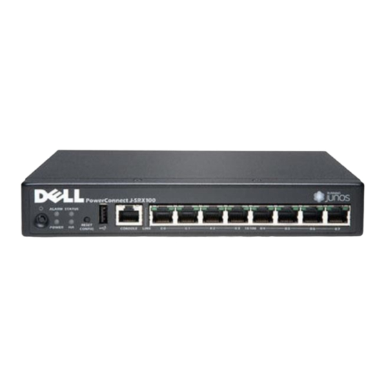
Chapter 2: J-SRX100 Services Gateway Hardware Components and Specifications J-SRX100 Services Gateway Front Panel and Back Panel Views This topic contains views of the front and back panels of the J-SRX100 Services Gateway. This topic includes the following sections: J-SRX100 Services Gateway Front Panel on page 9 J-SRX100 Services Gateway Back Panel on page 10 J-SRX100 Services Gateway Front Panel Figure 2 on page 9 shows the front panel of the J-SRX100 Services Gateway. -
Page 24: J-Srx100 Services Gateway Back Panel
PowerConnect J-SRX100 Services Gateway Hardware Guide J-SRX100 Services Gateway Back Panel Figure 3 on page 10 illustrates the back panel of the J-SRX100 Services Gateway. Figure 3: J-SRX100 Services Gateway Back Panel Table 7 on page 10 lists the components available on the back panel of the J-SRX100 Services Gateway. - Page 25 Chapter 2: J-SRX100 Services Gateway Hardware Components and Specifications Table 8: J-SRX100 Services Gateway Built-In Hardware Interfaces Interface Type Specifications Description Fast Ethernet The Fast Ethernet ports: The Fast Ethernet ports can be used: Consist of eight fixed ports To provide LAN connectivity Are labeled as port 0/0 to to hubs, switches, local port 0/7 on the front panel...
-
Page 26: J-Srx100 Services Gateway Leds
PowerConnect J-SRX100 Services Gateway Hardware Guide CAUTION: Pressing and holding the Reset Config button for 15 seconds or more deletes all configurations on the device and loads and commits the factory configuration. Related J-SRX100 Services Gateway Specifications on page 7... - Page 27 Chapter 2: J-SRX100 Services Gateway Hardware Components and Specifications Table 9: J-SRX100 Services Gateway Front Panel LEDs Number Component Description Usage Alarm LED The Alarm LED has The Alarm LED can be the following indicator used to gather colors: information on major or minor alarms or to Red and steadily on determine if the...
-
Page 28: J-Srx100 Services Gateway Ethernet Port Leds
PowerConnect J-SRX100 Services Gateway Hardware Guide Table 9: J-SRX100 Services Gateway Front Panel LEDs (continued) Number Component Description Usage HA LED The HA LED has the The HA LED can be following indicator used to determine if colors: chassis clustering is enabled on the device. -
Page 29: J-Srx100 Services Gateway Boot Devices
Chapter 2: J-SRX100 Services Gateway Hardware Components and Specifications Figure 5: J-SRX100 Services Gateway Ethernet Port LEDs The below table applies only to LED marked 1. Table 10 on page 15 provides the states of this LED. Table 10: J-SRX100 Services Gateway Built-In Ethernet Port LEDs Function Color State... -
Page 30: J-Srx100 Services Gateway Power Supply
NOTE: The power supply adapter (30 W) and the 2-prong power cord are shipped separately for the J-SRX100S and J-SRX100SU models. Contact your Dell customer service representative for more information. Related J-SRX100 Services Gateway Specifications on page 7... -
Page 31: Setting Up The J-Srx100 Services Gateway
PART 2 Setting Up the J-SRX100 Services Gateway Preparing the Site for J-SRX100 Services Gateway Installation on page 19 Installation Overview for the J-SRX100 Services Gateway on page 27 Required Tools and Parts for Installing and Maintaining the J-SRX100 Services Gateway on page 31 Unpacking the J-SRX100 Services Gateway on page 33 Preparing the J-SRX100 Services Gateway for Installation on page 37... - Page 32 PowerConnect J-SRX100 Services Gateway Hardware Guide...
-
Page 33: Preparing The Site For J-Srx100 Services Gateway Installation
CHAPTER 3 Preparing the Site for J-SRX100 Services Gateway Installation This chapter provides a checklist to help you prepare your site for installation of the J-SRX100 Services Gateway. Read this chapter to make sure that your site has the proper operating environment and equipment. - Page 34 PowerConnect J-SRX100 Services Gateway Hardware Guide Table 11: Site Preparation Checklist for Services Gateway Installation (continued) Additional Item or Task Information Performed By Date Notes Measure the distance “J-SRX100 between the external Services power sources and Gateway Site the device installation Electrical Wiring site.
- Page 35 Chapter 3: Preparing the Site for J-SRX100 Services Gateway Installation Table 11: Site Preparation Checklist for Services Gateway Installation (continued) Additional Item or Task Information Performed By Date Notes Verify that the area “Preparing the selected meets the J-SRX100 minimum Services requirements.
-
Page 36: General Site Guidelines For Installing The J-Srx100 Services Gateway
PowerConnect J-SRX100 Services Gateway Hardware Guide General Site Guidelines for Installing the J-SRX100 Services Gateway Keep the following precautions in mind to help you plan an acceptable operating environment for your J-SRX100 Services Gateway and avoid environmentally caused equipment failures: For the operating temperature of the services gateway to be optimal, the airflow around the chassis must be unrestricted. -
Page 37: J-Srx100 Services Gateway Rack Requirements
Chapter 3: Preparing the Site for J-SRX100 Services Gateway Installation Table 12: J-SRX100 Services Gateway Cabinet Requirements (continued) Cabinet Requirements Specifications Clearance The cabinet is at least 1 U (1.75 in. or 4.5 cm) high. requirements The outer edges of the mounting brackets extend the width of either chassis to 19 in. -
Page 38: Clearance Requirements For Airflow And Hardware Maintenance Of The J-Srx100
PowerConnect J-SRX100 Services Gateway Hardware Guide Table 13: Rack Requirements for the Services Gateway Rack Requirements Specifications Rack Size A 19 in. (48.3 cm) rack as defined in Cabinets, Racks, Panels, and Associated Equipment (document number EIA-310-D) published by the http://www.eia.org... - Page 39 Chapter 3: Preparing the Site for J-SRX100 Services Gateway Installation If you are mounting the device in a rack with other equipment, or if you are placing it on the desktop near other equipment, ensure that the exhaust from other equipment does not blow into the intake vents of the chassis.
-
Page 40: J-Srx100 Services Gateway Electrical And Power Requirements
PowerConnect J-SRX100 Services Gateway Hardware Guide J-SRX100 Services Gateway Electrical and Power Requirements This topic provides information on the factors you must consider while planning the electrical wiring and power availability at your site. These requirements cover the following areas:... -
Page 41: Installation Overview For The J-Srx100 Services Gateway
CHAPTER 4 Installation Overview for the J-SRX100 Services Gateway This chapter includes the following section: Installation Overview for the J-SRX100 Services Gateway on page 28... -
Page 42: Installation Overview For The J-Srx100 Services Gateway
PowerConnect J-SRX100 Services Gateway Hardware Guide Installation Overview for the J-SRX100 Services Gateway After you have prepared your installation site, you are ready to unpack and install the services gateway. It is important to proceed through the installation process in the order shown in Table 15 on page 28. - Page 43 Chapter 4: Installation Overview for the J-SRX100 Services Gateway Documentation General Site Guidelines for Installing the J-SRX100 Services Gateway on page 22 Preparing the J-SRX100 Services Gateway for Rack-Mount Installation on page 37 Preparing the J-SRX100 Services Gateway for Desk-Mount Installation on page 38 Preparing the J-SRX100 Services Gateway for Wall-Mount Installation on page 38 Installing the J-SRX100 Services Gateway in a Rack on page 42 Installing the J-SRX100 Services Gateway on a Desk on page 46...
- Page 44 PowerConnect J-SRX100 Services Gateway Hardware Guide...
-
Page 45: Required Tools And Parts For Installing And Maintaining The J-Srx100
CHAPTER 5 Required Tools and Parts for Installing and Maintaining the J-SRX100 Services Gateway This chapter includes the following section: Required Tools and Parts for Installing and Maintaining the J-SRX100 Services Gateway on page 31 Required Tools and Parts for Installing and Maintaining the J-SRX100 Services Gateway Table 16 on page 31 lists the tools and parts required to install and maintain the J-SRX100 Services Gateway. - Page 46 PowerConnect J-SRX100 Services Gateway Hardware Guide Table 16: Required Tools and Parts for Installing and Maintaining the J-SRX100 Services Gateway (continued) Task Tools and Parts Related Topic Packing the J-SRX100 Services Electrostatic bag or “Packing the J-SRX100 Gateway antistatic mat, for each...
-
Page 47: Unpacking The J-Srx100 Services Gateway
CHAPTER 6 Unpacking the J-SRX100 Services Gateway This chapter includes the following sections: Unpacking the J-SRX100 Services Gateway on page 33 Verifying Parts Received with the J-SRX100 Services Gateway on page 34 Unpacking the J-SRX100 Services Gateway The J-SRX100 Services Gateway is shipped in a cardboard carton. The carton also contains an accessory box and the J-SRX100 Services Gateway Quick Start Guide. -
Page 48: Verifying Parts Received With The J-Srx100 Services Gateway
The packing list specifies the part numbers and descriptions of each part in your order. If any part is missing, contact Dell Support. A fully configured J-SRX100 Services Gateway contains the chassis with installed components, listed in Table 17 on page 34, and an accessory box, which contains the parts listed in Table 18 on page 34. - Page 49 Chapter 6: Unpacking the J-SRX100 Services Gateway NOTE: The mounting kits available for rack, desk, and wall installation of the J-SRX100 Services Gateway must be ordered separately. Contact Dell Support for more information. Related Required Tools and Parts for Installing and Maintaining the J-SRX100 Services Gateway...
- Page 50 PowerConnect J-SRX100 Services Gateway Hardware Guide...
-
Page 51: Preparing The J-Srx100 Services Gateway For Installation
CHAPTER 7 Preparing the J-SRX100 Services Gateway for Installation This chapter includes the following sections: Preparing the J-SRX100 Services Gateway for Rack-Mount Installation on page 37 Preparing the J-SRX100 Services Gateway for Desk-Mount Installation on page 38 Preparing the J-SRX100 Services Gateway for Wall-Mount Installation on page 38 Preparing the J-SRX100 Services Gateway for Rack-Mount Installation You can mount a J-SRX100 Services Gateway in four-post (telco) racks, enclosed cabinets, and open-frame racks. -
Page 52: Preparing The J-Srx100 Services Gateway For Desk-Mount Installation
PowerConnect J-SRX100 Services Gateway Hardware Guide NOTE: The rack-mounting kit is not shipped with the device and must be ordered separately. Preparing the J-SRX100 Services Gateway for Desk-Mount Installation You can mount a J-SRX100 Services Gateway on a desk or other level surface horizontally or vertically. -
Page 53: Preparing The J-Srx100 Services Gateway For Rack-Mount Installation
Chapter 7: Preparing the J-SRX100 Services Gateway for Installation Remove the services gateway chassis from the shipping carton. For unpacking instructions, see “Unpacking the J-SRX100 Services Gateway” on page 33. Verify that you have the following parts available in your wall-mounting kit for the J-SRX100 Services Gateway: Wall-mounting brackets Screws... - Page 54 PowerConnect J-SRX100 Services Gateway Hardware Guide...
-
Page 55: Installing The J-Srx100 Services Gateway
CHAPTER 8 Installing the J-SRX100 Services Gateway This chapter includes the following sections: J-SRX100 Services Gateway Safety Requirements, Warnings, and Guidelines on page 41 Installing the J-SRX100 Services Gateway on page 41 J-SRX100 Services Gateway Safety Requirements, Warnings, and Guidelines To avoid harm to yourself or the device as you install and maintain it, follow the guidelines for working with and near electrical equipment, as well as the safety procedures for working with devices. -
Page 56: Installing The J-Srx100 Services Gateway In A Rack
PowerConnect J-SRX100 Services Gateway Hardware Guide Installing the J-SRX100 Services Gateway on a Desk on page 46 Installing the J-SRX100 Services Gateway on a Wall on page 47 Installing the J-SRX100 Services Gateway in a Rack You can front-mount two J-SRX100 Services Gateways in a rack. Many types of racks are acceptable, including four-post (telco) racks, enclosed cabinets, and open-frame racks. -
Page 57: Installing The J-Srx100 Services Gateway In A Non-Telco Rack
Chapter 8: Installing the J-SRX100 Services Gateway Figure 7: Hanging the J-SRX100 Services Gateway in a Rack Have a second person install a mounting screw into each of the two aligned holes. Use a number-3 Phillips screwdriver to install the mounting screws. Install the second screw in each side of the rack-mount tray. - Page 58 PowerConnect J-SRX100 Services Gateway Hardware Guide Figure 8: Installing a Cage Nut Using a Cage-Nut-Insertion Tool d. Pull the tool and the cage nut back through the slot. e. Proceed to Step 2—Installing the J-SRX100 Services Gateway in a Non-Telco Rack.
- Page 59 Chapter 8: Installing the J-SRX100 Services Gateway a. Position the device or devices in the rack-mount tray as shown in Figure 10 on page 45. Although the figure shows two devices, you can also use the following procedure to install one device. Figure 10: Installing the J-SRX100 Services Gateway in a Rack b.
-
Page 60: Installing The J-Srx100 Services Gateway On A Desk
PowerConnect J-SRX100 Services Gateway Hardware Guide f. Install the second set of 10-32 screws with washers in each side of the rack-mount tray. g. Verify that the mounting screws on one side of the rack-mount tray are aligned with the mounting screws on the opposite side and that the tray is level. -
Page 61: Installing The J-Srx100 Services Gateway On A Wall
Chapter 8: Installing the J-SRX100 Services Gateway The vertical position requires the vertical installation kit, which consists of a vertical installation stand. To install the device in a vertical position: Place the device on a flat and level surface with the logo facing up, as shown in Figure 12 on page 47. - Page 62 PowerConnect J-SRX100 Services Gateway Hardware Guide Place the device on a flat and level surface with the logo facing up. Position a mounting bracket on each side of the chassis as shown in Figure 13 on page 48. Figure 13: Installing the J-SRX100 Services Gateway on a Wall Use a number–1 Phillips screwdriver to install the screws that secure the mounting...
- Page 63 Chapter 8: Installing the J-SRX100 Services Gateway Figure 14: Hanging the J-SRX100 Services Gateway on a Wall Related Required Tools and Parts for Installing and Maintaining the J-SRX100 Services Gateway Documentation on page 31 Preparing the J-SRX100 Services Gateway for Wall-Mount Installation on page 38 J-SRX100 Services Gateway Safety Requirements, Warnings, and Guidelines on page 41 Installing the J-SRX100 Services Gateway on a Desk on page 46 Installing the J-SRX100 Services Gateway in a Rack on page 42...
- Page 64 PowerConnect J-SRX100 Services Gateway Hardware Guide...
-
Page 65: Connecting, Grounding, And Powering On The J-Srx100 Services
NOTE: The power supply adapter (30 W) and the 2-prong power cord are shipped separately for the J-SRX100S and J-SRX100SU models. Contact your Dell customer service representative for more information. To connect the device to the power supply: CAUTION: Before connecting the device to the power supply, attach an ESD strap to an ESD point and place the other end of the strap around your bare wrist. -
Page 66: Connecting And Organizing Interface Cables To The J-Srx100 Services Gateway
PowerConnect J-SRX100 Services Gateway Hardware Guide Figure 15: Connecting the Services Gateway to Power Supply NOTE: The device must be connected to earth ground during normal operation. The protective earthing terminal on the rear of the chassis is provided to connect the device to ground. -
Page 67: Grounding The J-Srx100 Services Gateway
Chapter 9: Connecting, Grounding, and Powering On the J-SRX100 Services Gateway transmit data. You must configure each network interface before it can operate on the device. To connect and organize an interface cable to the device: Have ready a length of the type of cable used by the interface. Insert the cable connector into the cable connector port on the interface faceplate. - Page 68 PowerConnect J-SRX100 Services Gateway Hardware Guide CAUTION: Before device installation begins, a licensed electrician must attach a cable lug to the grounding and power cables that you use. A cable with an incorrectly attached lug can damage the device (for example, by causing a short circuit).
-
Page 69: Powering On And Powering Off The J-Srx100 Services Gateway
Chapter 9: Connecting, Grounding, and Powering On the J-SRX100 Services Gateway Related Connecting the J-SRX100 Services Gateway to the Power Supply on page 51 Documentation Connecting and Organizing Interface Cables to the J-SRX100 Services Gateway on page 52 J-SRX100 Services Gateway General Safety Guidelines and Warnings on page 101 Powering On and Powering Off the J-SRX100 Services Gateway on page 55 Using the Reset Config Button on the J-SRX100 Services Gateway on page 93 Changing the Reset Config Button Behavior on the J-SRX100 Services Gateway on... - Page 70 PowerConnect J-SRX100 Services Gateway Hardware Guide Graceful shutdown—Press and immediately release the Power button. The device begins gracefully shutting down the operating system and then powers itself off. WARNING: Use the graceful shutdown method to power off or reboot the services gateway.
- Page 71 Chapter 9: Connecting, Grounding, and Powering On the J-SRX100 Services Gateway For more information about halting, powering off, or rebooting the services gateway using CLI, see the Junos OS Administration Guide. Related J-SRX100 Services Gateway Front Panel and Back Panel Views on page 9 Documentation Connecting the J-SRX100 Services Gateway to the Power Supply on page 51 Grounding the J-SRX100 Services Gateway on page 53...
- Page 72 PowerConnect J-SRX100 Services Gateway Hardware Guide...
-
Page 73: J-Srx100 Services Gateway Memory Upgrade
CHAPTER 10 J-SRX100 Services Gateway Memory Upgrade This chapter includes the following section: Upgrading the J-SRX100 Services Gateway Low Memory Version to a High Memory Version on page 59 Upgrading the J-SRX100 Services Gateway Low Memory Version to a High Memory Version Based on your requirements, you can upgrade from a J-SRX100 Services Gateway Low Memory version to a High Memory version through a license key. - Page 74 PowerConnect J-SRX100 Services Gateway Hardware Guide For more information on generating, installing, and managing licenses, see the Junos OS Administration Guide. To obtain a memory license, contact Dell Support. Related J-SRX100 Services Gateway Features and Functions on page 5 Documentation...
-
Page 75: J-Srx100 Services Gateway Autoinstallation
CHAPTER 11 J-SRX100 Services Gateway Autoinstallation This chapter includes the following section: J-SRX100 Services Gateway Autoinstallation Overview on page 61 J-SRX100 Services Gateway Autoinstallation Overview The autoinstallation process begins any time a services gateway is powered on and cannot locate a valid configuration file in the internal flash. Typically, a configuration file is unavailable when a services gateway is powered on for the first time or if the configuration file is deleted from the internal flash. - Page 76 PowerConnect J-SRX100 Services Gateway Hardware Guide...
-
Page 77: Connecting The J-Srx100 Services Gateway To Management Devices
CHAPTER 12 Connecting the J-SRX100 Services Gateway to Management Devices This chapter includes the following sections: Connecting a J-SRX100 Services Gateway to the J-Web Interface on page 63 Connecting the J-SRX100 Services Gateway to the CLI on page 65 Connecting the Modem at the J-SRX100 Services Gateway End on page 67 Connecting the Modem to the Console Port on the J-SRX100 Services Gateway on page 68 Connecting to the CLI at the User End for the J-SRX100 Services Gateway on page 69... - Page 78 PowerConnect J-SRX100 Services Gateway Hardware Guide Figure 17: Connecting to the Ethernet Port on a J-SRX100 Services Gateway From the management device you use to access the J-Web interface (such as a PC or a laptop), verify that the address of the port you connect to is set to one of the...
-
Page 79: Connecting The J-Srx100 Services Gateway To The Cli
Chapter 12: Connecting the J-SRX100 Services Gateway to Management Devices NOTE: You must manually configure the IP address for the management port you are using before you save your initial configuration. When you save the configuration for the first time, you will lose the connection to the services gateway if you have not manually configured the IP address. - Page 80 PowerConnect J-SRX100 Services Gateway Hardware Guide NOTE: Figure 18 on page 65 shows a connection to a local management device. A remote connection to the services gateway through a modem requires the cable and connector shown (provided in the services gateway accessory box), plus a DB-9 female to DB-25 male (or similar) adapter for your modem, which you must purchase separately.
-
Page 81: Connecting A J-Srx100 Services Gateway To The Cli Remotely
Chapter 12: Connecting the J-SRX100 Services Gateway to Management Devices Connecting a J-SRX100 Services Gateway to the CLI Remotely You can connect a J-SRX100 Services Gateway to the CLI from a remote location through two dial-up modems: A modem that is connected to the console port on the services gateway A second modem connected to a remote management device The modem connection allows you to remotely perform the same console operations you can perform locally. -
Page 82: Gateway
PowerConnect J-SRX100 Services Gateway Hardware Guide Table 22: Port Settings for Configuring the Modem on the Services Gateway End (continued) Port Settings Value Flow control None In the HyperTerminal window, enter For more information on the AT commands, see the Junos OS Administration Guide. -
Page 83: Connecting To The Cli At The User End For The J-Srx100 Services Gateway
Chapter 12: Connecting the J-SRX100 Services Gateway to Management Devices NOTE: Most modems have an RS-232 DB-25 connector. You must separately purchase an adapter to connect your modem to the RJ-45 to DB-9 adapter and the Ethernet cable supplied with the services gateway. Related Connecting the Modem at the J-SRX100 Services Gateway End on page 67 Documentation... - Page 84 PowerConnect J-SRX100 Services Gateway Hardware Guide The services gateway login prompt appears. Log in as the user root . No password is required at initial connection, but you must assign a root password before committing any configuration settings. Related Connecting the Modem at the J-SRX100 Services Gateway End on page 67...
-
Page 85: Gateway
CHAPTER 13 Performing Initial Software Configuration on the J-SRX100 Services Gateway This chapter includes the following sections: J-SRX100 Services Gateway Software Configuration Overview on page 71 Performing Initial Software Configuration on the J-SRX100 Services Gateway Using the CLI on page 74 Performing Initial Software Configuration on the J-SRX100 Services Gateway Using the J-Web Interface on page 77 J-SRX100 Services Gateway Secure Web Access Overview on page 81... -
Page 86: Understanding Built-In Ethernet Ports
PowerConnect J-SRX100 Services Gateway Hardware Guide NOTE: The J-SRX100 Services Gateway that ship with JUNOS Release 10.0 or later are formatted with dual-root partitions from the factory. For more information on dual-root partitioning, see the Junos OS Administration Guide for Security Devices. -
Page 87: Understanding Management Access
Chapter 13: Performing Initial Software Configuration on the J-SRX100 Services Gateway Table 25: Mapping the Chassis Cluster Ports on a J-SRX100 Services Gateway FE Ports on J-SRX100 Services Gateway Management Interface fe-0/0/6 fxp0 (management port) fe-0/0/7 fxp1 (control port) Junos OS automatically creates the fxp0 and fxp1 interfaces on these ports when the J-SRX100 Services Gateway is operating in chassis cluster mode. -
Page 88: Using The Cli
PowerConnect J-SRX100 Services Gateway Hardware Guide NOTE: Information sent in cleartext is not encrypted and therefore can be intercepted. If the device is operating in a Common Criteria environment, see the Secure Configuration Guide for Common Criteria and JUNOS-FIPS. Related... -
Page 89: Performing Initial Software Configuration On The J-Srx100 Services Gateway
Chapter 13: Performing Initial Software Configuration on the J-SRX100 Services Gateway Commit the configuration to activate it on the device. [edit] root@# commit Log in as the administrative user you configured in Step 6. Configure the name of the device. If the name includes spaces, enclose the name in quotation marks (“... - Page 90 PowerConnect J-SRX100 Services Gateway Hardware Guide system { host-name devicea; domain-name lab.device.net; domain-search [ lab.device.net device.net ]; backup-device 192.168.2.44; time-zone America/Los_Angeles; root-authentication { ssh-rsa "ssh-rsa AAAAB3Nza...D9Y2gXF9ac==root@devicea.lab.device.net"; name-server { 10.148.2.32; services { ntp { server 10.148.2.21; interfaces { fe-0/0/0 { unit 0 { family inet { address 192.168.1.1/24;...
-
Page 91: Performing Initial Software Configuration On The J-Srx100 Services Gateway Using The J-Web Interface
Chapter 13: Performing Initial Software Configuration on the J-SRX100 Services Gateway J-SRX100 Services Gateway Secure Web Access Overview on page 81 Performing Initial Software Configuration on the J-SRX100 Services Gateway Using the J-Web Interface This topic includes the following sections: Establishing Basic Connectivity on page 77 Configuring Basic System Properties on page 78 Establishing Basic Connectivity... -
Page 92: Configuring Basic System Properties
PowerConnect J-SRX100 Services Gateway Hardware Guide NOTE: All network and management access settings are optional. Click Apply to apply the configuration. NOTE: After configuring the basic settings, the Web session may timeout. Refresh or relaunch the page if the applied configuration page is not displayed . - Page 93 Chapter 13: Performing Initial Software Configuration on the J-SRX100 Services Gateway Table 27: Basic Configuration Summary (Management Access) Field Function Your Action Default Gateway Defines a default gateway through which Type a 32-bit IP address in to direct packets addressed to networks dotted decimal notation.
- Page 94 PowerConnect J-SRX100 Services Gateway Hardware Guide To configure basic system properties: In the J-Web interface, select Configure> System properties and select the required tab and proceed with configuring the other settings. See Table 26 on page 78 through Table 28 on page 79 for details.
-
Page 95: J-Srx100 Services Gateway Secure Web Access Overview
Chapter 13: Performing Initial Software Configuration on the J-SRX100 Services Gateway Scroll down to the Interfaces Configuration panel on the page to add an interface to a specific zone. Click OK to save the configuration. Configure basic security policies. In the J-Web interface, under the Configure tab, navigate to Security > Policy. In the Security Policy page, click Add. - Page 96 PowerConnect J-SRX100 Services Gateway Hardware Guide Without SSL encryption, communication between your services gateway and the browser is sent in the open and can be intercepted. We recommend that you enable HTTPS access on your WAN interfaces. For more information about configuring secure Web access, see the Junos OS Administration Guide.
-
Page 97: Part 3 Maintaining And Monitoring The J-Srx100 Services Gateway
PART 3 Maintaining and Monitoring the J-SRX100 Services Gateway Maintaining the J-SRX100 Services Gateway Hardware Components on page 85 Monitoring the J-SRX100 Services Gateway on page 87... - Page 98 PowerConnect J-SRX100 Services Gateway Hardware Guide...
-
Page 99: Maintaining The J-Srx100 Services Gateway Hardware Components
CHAPTER 14 Maintaining the J-SRX100 Services Gateway Hardware Components This chapter describes how to maintain the hardware components of the J-SRX100 Services Gateway. This chapter includes the following section: Maintaining the J-SRX100 Services Gateway Hardware Components on page 85 Maintaining the J-SRX100 Services Gateway Hardware Components Table 29 on page 85 describes the common tasks for maintaining the hardware components of the services gateway. - Page 100 PowerConnect J-SRX100 Services Gateway Hardware Guide Monitoring the J-SRX100 Services Gateway Components Using LEDs on page 89 Monitoring the J-SRX100 Services Gateway Using Chassis Alarm Conditions on page 91 Monitoring the J-SRX100 Services Gateway Power System on page 92...
-
Page 101: Monitoring The J-Srx100 Services Gateway
Monitoring the Hardware Components on the J-SRX100 Services Gateway on page 87 Resetting the Configuration File When the J-SRX100 Services Gateway Is Inaccessible on page 93 Dell Support on page 95 Monitoring the Hardware Components on the J-SRX100 Services Gateway This topic includes the following sections:... - Page 102 PowerConnect J-SRX100 Services Gateway Hardware Guide Examples: The following examples provide the sample output of commands: show chassis hardware user@host > show chassis hardware Item Version Part number Serial number Description Chassis AU0209AF0022 Dell J-SRX100S Routing Engine REV 00 750-02177...
-
Page 103: Monitoring The J-Srx100 Services Gateway Components Using Leds
Maintaining the J-SRX100 Services Gateway Hardware Components on page 85 Using the Reset Config Button on the J-SRX100 Services Gateway on page 93 Dell Support on page 95 Monitoring the J-SRX100 Services Gateway Components Using LEDs Table 30 on page 89 describes the status of the LEDs on startup of the device. - Page 104 PowerConnect J-SRX100 Services Gateway Hardware Guide Table 30: Services Gateway LED Status on Startup (continued) State Description Power LED Green Indicates that the device is receiving normal power supply. HA LED Indicates that the device is not part of chassis clustering set up.
-
Page 105: Monitoring The J-Srx100 Services Gateway Using Chassis Alarm
Changing the Reset Config Button Behavior on the J-SRX100 Services Gateway on page 94 Dell Support on page 95 Monitoring the J-SRX100 Services Gateway Using Chassis Alarm Conditions When the services gateway detects an alarm condition, the alarm LED on the front panel turns red or amber as appropriate. -
Page 106: Monitoring The J-Srx100 Services Gateway Power System
PowerConnect J-SRX100 Services Gateway Hardware Guide Table 32 on page 92 describes alarms that can occur for a J-SRX100 Services Gateway chassis component. Table 32: J-SRX100 Services Gateway Chassis Alarm Conditions and Corrective Actions Alarm Component Alarm Conditions Action Severity... -
Page 107: Inaccessible
Ensure the device has an AC input voltage between 100 and 240 VAC. If you cannot determine the cause of the problem or need additional assistance, see “Dell Support” on page 95. Related Monitoring the J-SRX100 Services Gateway Chassis Using the CLI on page 87... - Page 108 PowerConnect J-SRX100 Services Gateway Hardware Guide a rescue configuration. For example, if someone inadvertently commits a configuration that denies management access to a services gateway, you can delete the invalid configuration and replace it with a rescue configuration by pressing the Reset Config button.
-
Page 109: Dell Support
Dell Support on page 95 Dell Support This topic includes the following section: Dell Support on page 95 Dell Support If you need assistance while troubleshooting a services gateway, please go to the Dell Support website at http://www.support.dell.com Related Contacting Dell on page 135... - Page 110 PowerConnect J-SRX100 Services Gateway Hardware Guide...
-
Page 111: Appendixes
PART 4 Appendixes Safety and Regulatory Compliance Information on page 99 J-SRX100 Services Gateway Power Guidelines, Requirements, and Specifications on page 123 J-SRX100 Services Gateway Interface Cable Specifications and Connector Pinouts on page 127 Getting Help on page 131... - Page 112 PowerConnect J-SRX100 Services Gateway Hardware Guide...
-
Page 113: Appendix A Safety And Regulatory Compliance Information
APPENDIX A Safety and Regulatory Compliance Information This appendix includes the following sections: J-SRX100 Services Gateway Definition of Safety Warning Levels on page 99 J-SRX100 Services Gateway General Safety Guidelines and Warnings on page 101 J-SRX100 Services Gateway Fire Safety Requirements on page 104 J-SRX100 Services Gateway Installation Safety Guidelines and Warnings on page 105 J-SRX100 Services Gateway Laser and LED Safety Guidelines and Warnings on page 110 J-SRX100 Services Gateway Maintenance and Operational Safety Guidelines and... - Page 114 PowerConnect J-SRX100 Services Gateway Hardware Guide involved with electrical circuitry and be familiar with standard practices for preventing accidents. Waarschuwing Dit waarschuwingssymbool betekent gevaar. U verkeert in een situatie die lichamelijk letsel kan veroorzaken. Voordat u aan enige apparatuur gaat werken, dient u zich bewust te zijn van de bij elektrische schakelingen betrokken risico's en dient u op de hoogte te zijn van standaard maatregelen om ongelukken te voorkomen.
-
Page 115: J-Srx100 Services Gateway General Safety Guidelines And Warnings
Appendix A: Safety and Regulatory Compliance Information måste du vara medveten om farorna med elkretsar och känna till vanligt förfarande för att förebygga skador. Related J-SRX100 Services Gateway General Safety Guidelines and Warnings on page 101 Documentation J-SRX100 Services Gateway Fire Safety Requirements on page 104 J-SRX100 Services Gateway Installation Safety Guidelines and Warnings on page 105 J-SRX100 Services Gateway Laser and LED Safety Guidelines and Warnings on page 110 J-SRX100 Services Gateway Electrical Safety Guidelines and Warnings on page 118... - Page 116 PowerConnect J-SRX100 Services Gateway Hardware Guide Qualified Personnel Warning WARNING: Only trained and qualified personnel should install or replace the services gateway. Waarschuwing Installatie en reparaties mogen uitsluitend door getraind en bevoegd personeel uitgevoerd worden. Varoitus Ainoastaan koulutettu ja pätevä henkilökunta saa asentaa tai vaihtaa tämän laitteen.
- Page 117 Appendix A: Safety and Regulatory Compliance Information tai jonkin muun turvalaitteen avulla ja joka on paikasta vastuussa olevien toimivaltaisten henkilöiden valvoma. Attention Cet appareil est à installer dans des zones d'accès réservé. Ces dernières sont des zones auxquelles seul le personnel de service peut accéder en utilisant un outil spécial, un mécanisme de verrouillage et une clé, ou tout autre moyen de sécurité.
-
Page 118: J-Srx100 Services Gateway Fire Safety Requirements
PowerConnect J-SRX100 Services Gateway Hardware Guide Many services gateway hardware components are sensitive to damage from static electricity. Some components can be impaired by voltages as low as 30 V. You can easily generate potentially damaging static voltages whenever you handle plastic or foam packing material or if you move components across plastic or carpets. -
Page 119: J-Srx100 Services Gateway Installation Safety Guidelines And Warnings
Appendix A: Safety and Regulatory Compliance Information equipment. We recommend that fire suppression equipment be available in the event of a fire in the vicinity of the equipment and that all local fire, safety, and electrical codes and ordinances be observed when installing and operating your equipment. In the event of an electrical hazard or an electrical fire, first turn power off to the equipment at the source. - Page 120 PowerConnect J-SRX100 Services Gateway Hardware Guide Attention Avant de brancher le système sur la source d'alimentation, consulter les directives d'installation. Warnung Lesen Sie die Installationsanweisungen, bevor Sie das System an die Stromquelle anschließen. Avvertenza Consultare le istruzioni di installazione prima di collegare il sistema all'alimentatore.
- Page 121 Appendix A: Safety and Regulatory Compliance Information De J-SRX Series services gateway moet in een stellage worden geïnstalleerd die aan een bouwsel is verankerd. Dit toestel dient onderaan in het rek gemonteerd te worden als het toestel het enige in het rek is. Wanneer u dit toestel in een gedeeltelijk gevuld rek monteert, dient u het rek van onderen naar boven te laden met het zwaarste onderdeel onderaan in het rek.
- Page 122 Se il supporto è dotato di dispositivi stabilizzanti, installare tali dispositivi prima di montare o di procedere alla manutenzione dell'unità nel supporto. Advarsel Unngå fysiske skader under montering eller reparasjonsarbeid på denne enheten når den befinner seg i et kabinett. Vær nøye med at systemet er stabilt.
- Page 123 Appendix A: Safety and Regulatory Compliance Information de que o sistema possui um suporte estável. As seguintes directrizes ajudá-lo-ão a efectuar o seu trabalho com segurança: O J-SRX Series services gateway deverá ser instalado numa prateleira fixa à estrutura do edificio. Esta unidade deverá...
-
Page 124: J-Srx100 Services Gateway Laser And Led Safety Guidelines And Warnings
PowerConnect J-SRX100 Services Gateway Hardware Guide J-SRX100 Services Gateway Laser and LED Safety Guidelines and Warnings on page 110 J-SRX100 Services Gateway Laser and LED Safety Guidelines and Warnings Observe the following guidelines and warnings when working around the J-SRX100... -
Page 125: Class 1 Led Product Warning
Appendix A: Safety and Regulatory Compliance Information Class 1 LED Product Warning WARNING: Class 1 LED product. Waarschuwing Klasse 1 LED-product. Varoitus Luokan 1 valodiodituote. Attention Alarme de produit LED Class I. Warnung Class 1 LED-Produktwarnung. Avvertenza Avvertenza prodotto LED di Classe 1. Advarsel LED-produkt i klasse 1. -
Page 126: Radiation From Open Port Apertures Warning
PowerConnect J-SRX100 Services Gateway Hardware Guide Radiation from Open Port Apertures Warning WARNING: Because invisible radiation may be emitted from the aperture of the port when no fiber cable is connected, avoid exposure to radiation and do not stare into open apertures. -
Page 127: J-Srx100 Services Gateway Maintenance And Operational Safety Guidelines And Warnings
Appendix A: Safety and Regulatory Compliance Information J-SRX100 Services Gateway Maintenance and Operational Safety Guidelines and Warnings As you maintain the services gateway, observe the following guidelines and warnings: Safety Guidelines and Warnings on page 113 Safety Guidelines and Warnings Battery Handling Warning WARNING: Replacing the battery incorrectly might result in an explosion. -
Page 128: Jewelry Removal Warning
PowerConnect J-SRX100 Services Gateway Hardware Guide equivalente recomendado por el fabricante. Desechar las baterías gastadas según las instrucciones del fabricante. Varning! Explosionsfara vid felaktigt batteribyte. Ersätt endast batteriet med samma batterityp som rekommenderas av tillverkaren eller motsvarande. Följ tillverkarens anvisningar vid kassering av använda batterier. -
Page 129: Lightning Activity Warning
Appendix A: Safety and Regulatory Compliance Information Aviso Antes de trabalhar em equipamento que esteja ligado a linhas de corrente, retire todas as jóias que estiver a usar (incluindo anéis, fios e relógios). Os objectos metálicos aquecerão em contacto com a corrente e em contacto com a ligação à... -
Page 130: Operating Temperature Warning
Avvertenza Per evitare il surriscaldamento dei services gateway, non adoperateli in un locale che ecceda la temperatura ambientale massima di 40 C. Per evitare che la circolazione dell'aria sia impedita, lasciate uno spazio di almeno 15.2 cm di fronte alle aperture delle ventole. -
Page 131: Product Disposal Warning
Appendix A: Safety and Regulatory Compliance Information restricción de la entrada de aire, deje un espacio mínimo de 15,2 cm alrededor de las aperturas para ventilación. Varning! Förhindra att en J-SRX Series services gateway överhettas genom att inte använda den i ett område där den maximalt rekommenderade omgivningstemperaturen på... -
Page 132: J-Srx100 Services Gateway Electrical Safety Guidelines And Warnings
PowerConnect J-SRX100 Services Gateway Hardware Guide J-SRX100 Services Gateway Electrical Safety Guidelines and Warnings When working on equipment powered by electricity, follow the guidelines described in the following topics: Electrical Safety Guidelines and Warnings on page 118 Electrical Safety Guidelines and Warnings... -
Page 133: J-Srx100 Services Gateway Agency Approvals
Appendix A: Safety and Regulatory Compliance Information J-SRX100 Services Gateway Maintenance and Operational Safety Guidelines and Warnings on page 113 J-SRX100 Services Gateway Agency Approvals on page 119 Grounding the J-SRX100 Services Gateway on page 53 J-SRX100 Services Gateway Agency Approvals The services gateway complies with the following standards: Safety CSA 60950-1 (2003) Safety of Information Technology Equipment... -
Page 134: J-Srx100 Services Gateway Compliance Statements For Emc Requirements
PowerConnect J-SRX100 Services Gateway Hardware Guide Immunity EN 55024 +A1+A2 (1998) Information Technology Equipment Immunity Characteristics EN-61000-3-2 (2006) Power Line Harmonics EN-61000-3-3 +A1 +A2 +A3 (1995) Power Line Voltage Fluctuations EN-61000-4-2 +A1 +A2 (1995) Electrostatic Discharge EN-61000-4-3 +A1+A2 (2002) Radiated Immunity... -
Page 135: J-Srx100 Services Gateway Compliance Statements For Environmental Requirements
Appendix A: Safety and Regulatory Compliance Information a radio or television receiver in a domestic environment, it may cause radio interference. Install and use the equipment according to the instruction manual. United States This equipment has been tested and found to comply with the limits for a Class B digital device, pursuant to Part 15 of the FCC Rules. - Page 136 PowerConnect J-SRX100 Services Gateway Hardware Guide...
-
Page 137: J-Srx100 Services Gateway Power Guidelines, Requirements, And Specifications
APPENDIX B J-SRX100 Services Gateway Power Guidelines, Requirements, and Specifications This appendix includes the following sections: J-SRX100 Services Gateway Site Electrical Wiring Guidelines on page 123 J-SRX100 Services Gateway Power Specifications and Requirements on page 124 J-SRX100 Services Gateway Site Electrical Wiring Guidelines Table 34 on page 123 describes the factors you must consider while planning the electrical wiring for the services gateway at your site. -
Page 138: J-Srx100 Services Gateway Power Specifications And Requirements
PowerConnect J-SRX100 Services Gateway Hardware Guide Table 34: Site Electrical Wiring Guidelines for the Services Gateway (continued) Site Wiring Factor Guideline Radio Frequency To reduce or eliminate the emission of RFI from your site wiring: Interference (RFI) Use twisted-pair cable with a good distribution of grounding conductors. - Page 139 Appendix B: J-SRX100 Services Gateway Power Guidelines, Requirements, and Specifications Table 35: Power System Electrical Specifications for the J-SRX100 Services Gateway (continued) Power Requirement Specification AC system current rating 1 A maximum WARNING: The AC power cord for the services gateway is intended for use with the device only and not for any other use.
- Page 140 PowerConnect J-SRX100 Services Gateway Hardware Guide...
-
Page 141: Pinouts
APPENDIX C J-SRX100 Services Gateway Interface Cable Specifications and Connector Pinouts This appendix includes the following sections: Interface Cable and Wire Specifications for the J-SRX100 Services Gateway on page 127 RJ-45 Connector Pinouts for the J-SRX100 Services Gateway Ethernet Port on page 127 RJ-45 Connector Pinouts for the J-SRX100 Services Gateway Console Port on page 128 Interface Cable and Wire Specifications for the J-SRX100 Services Gateway Table 36 on page 127 lists the specifications for the cables that connect to ports. -
Page 142: Rj-45 Connector Pinouts For The J-Srx100 Services Gateway Console Port
PowerConnect J-SRX100 Services Gateway Hardware Guide Figure 20: Ethernet Cable Connector (RJ-45) Table 37 on page 128 describes the RJ-45 connector pinouts for the Ethernet port. Table 37: RJ-45 Connector Pinouts for the Services Gateway Ethernet Port Signal TX -... - Page 143 Appendix C: J-SRX100 Services Gateway Interface Cable Specifications and Connector Pinouts Table 38: RJ-45 Connector Pinouts for Services Gateway Console Port (continued) Signal Description Data Terminal Ready Transmit Data Ground Signal Ground Ground Signal Ground Receive Data DSR/DCD Data Set Ready Clear to Send Related Interface Cable and Wire Specifications for the J-SRX100 Services Gateway on page 127...
- Page 144 PowerConnect J-SRX100 Services Gateway Hardware Guide...
-
Page 145: Appendix D Getting Help
Use Dell's extensive suite of online services available at Dell Support ) for help with installation and troubleshooting http://www.support.dell.com procedures. See “Online Services” on page 132 for a more extensive list of Dell Support online. If the preceding steps have not resolved the problem, see “Contacting Dell” on page 135. -
Page 146: Online Services
PowerConnect J-SRX100 Services Gateway Hardware Guide NOTE: Dell's Express Service Code system may not be available in all countries. When prompted by Dell's automated telephone system, enter your Express Service Code to route the call directly to the proper support personnel. For instructions on using the Dell Support, see “Support Service”... -
Page 147: Automated Order-Status Service
Log in as user: anonymous, and use your e-mail address as your password. Automated Order-Status Service To check on the status of any Dell products that you have ordered, you can go to , or you can call the automated order-status service. A http://www.support.dell.com... -
Page 148: Before You Call
Remember to fill out the Diagnostics Checklist (see “Diagnostics Checklist” on page 134). If possible, turn on your computer before you call Dell for assistance and call from a telephone at or near the computer. You may be asked to type some commands at the keyboard, relay detailed information during operations, or try other troubleshooting steps possible only at the computer itself. -
Page 149: Contacting Dell
For customers in the United States, call 800-WWW.DELL (800.999.3355). NOTE: If you do not have an active Internet connection, you can find contact information on your purchase invoice, packing slip, bill, or Dell product catalog. Dell provides several online and telephone-based support and service options. Availability varies by country and product, and some services may not be available in your area. -
Page 150: Packing The J-Srx100 Services Gateway And Components For Shipment
PowerConnect J-SRX100 Services Gateway Hardware Guide FPC 0 PIC 0 8x FE Base PIC Power Supply 0 J-SRX100 Services Gateway Chassis Serial Number and Agency Labels The J-SRX100 Services Gateway has a serial number ID and agency labels on the bottom of the chassis as shown in Figure 22 on page 136. - Page 151 Appendix D: Getting Help On the console or other management device such as a PC or laptop connected to the services gateway, enter CLI operational mode and issue the following command to shut down the services gateway software: user@host> request system power-off Wait until a message appears on the console confirming that the operating system has halted.
-
Page 152: Dell Support
PowerConnect J-SRX100 Services Gateway Hardware Guide Dell Support on page 95 Dell Support If you need assistance while troubleshooting a services gateway, please go to the Dell Support website at http://www.support.dell.com... -
Page 153: Index
PART 5 Index Index on page 141... - Page 154 PowerConnect J-SRX100 Services Gateway Hardware Guide...
-
Page 155: Index
Index configuration Services Gateway............71 accessory list................34 connecting to CLI..............65 adapter, console port locally.................65 chassis................68 remotely................65 agency approvals..............119 connectivity Alarm LED...................13 through J-Web..............63 monitoring................89 console port altitude, acceptable range.............7 adapter (chassis)............68 approvals, agency..............119 cable specifications.............127 AT modem command...........67, 69 RJ-45.................128 AT&D1 modem command...........67 settings for modem connection at device for AT&K0 modem command..........67 remote CLI access.............67... - Page 156 PowerConnect J-SRX100 Services Gateway Hardware Guide Ethernet cable interface cables connecting the services gateway to a connecting................52 management device..........64 organizing................52 connecting the services gateway to a interfaces modem................68 built-in.................10 Ethernet port hardware................10 cable specifications.............127 internet..................3 RJ-45.................128 J-Web interface factory default configuration..........93 configuration editor See J-Web configuration fire safety specifications............104...
- Page 157 Index Reset Config button parts list..................34 CLI commands...............94 PC See management device set chassis commands..........94 pinouts using..................93 RJ-45.................127, 128 returning components............136 Port LED returning services gateway..........136 LINK..................14 RJ-45 pinouts port settings................67 console port..............128 power fast Ethernet port............127 shutdown................55 RJ-45 to DB-9 serial port adapter Power LED..................13 chassis console port.............68 monitoring................89...
- Page 158 PowerConnect J-SRX100 Services Gateway Hardware Guide parts..................31 wall installation power supply.............16, 55 preparing................38 powering off..............55 wall mount powering on..............55 preparing................38 rack installation..............42 warnings SSL access................81 electrical................118 tools..................31 wire specifications..............127 unpacking................33 use..................3 verifying parts..............34 wall installation...............47 Services Gateway configuration..............71 services gateway features High Memory..............5...