Table of Contents
Advertisement
Available languages
Available languages
Safety Instructions
. . . . . . .2, 3, 7
Operating Instructions
Cooking Tips . . . . . . . . . . . . . . . .5
Raise/Lower Switch . . . . . . . . . . .4
Using the Cooktop . . . . . . . . . . .4
Using the Downdraft System . . .4
Care and Cleaning
Grease Filters . . . . . . . . . . . . . . . .5
Painted or Metal Surfaces . . . . . .5
Stainless Steel Surfaces . . . . . . . .5
Advance Planning . . . . . . . . . .8, 9
Before You Begin . . . . . . . . . . . . .6
Units JVB37 and JVB94 . . . . . . .10
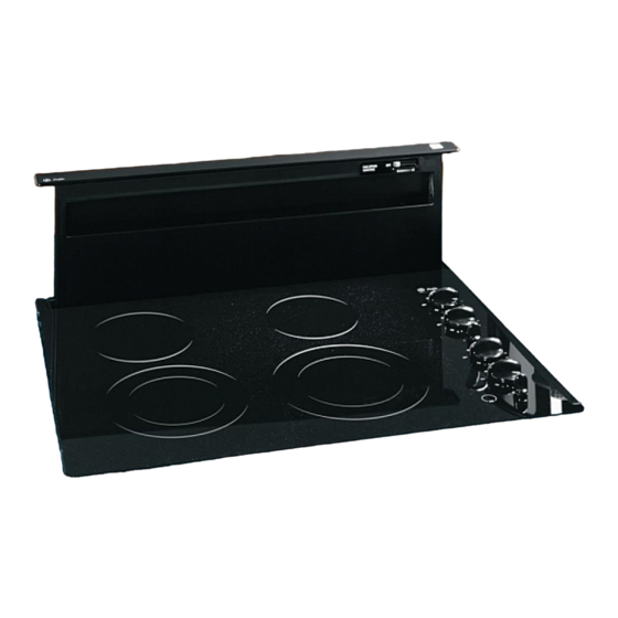
36" Cooktop/Downdraft
Units JVB67 and JVB98 . . . . . . .11
Dimensions and Clearances . .7, 8
Ductwork . . . . . . . . . . . . .8, 13, 15
Electrical and Gas Location . . . .8
Installation Possibilities . . . . . . . .9
Vent System . . . . . . . . . . . . .10-17
Optional Kits . . . . . . . . . . . . . . .17
Power Supply . . . . . . . . . . . . . . .12
Raise/Lower Switch . . . . . . . . . .16
Venting Options . . . . . . . . . . . .14
. . . . . . .18
Consumer Support
Consumer Support . . . . . . . . . .20
Warranty . . . . . . . . . . . . . . . . . . .19
Write the model and serial
numbers here:
Model # ______________________
Serial # ______________________
You can find them on a label on
the side of the blower housing.
ge.com
959-0445-000 49-80381 12-05 JR
Owner's Manual
& Installation
Instructions
JVB37
JVB67
JVB94
JVB98
Advertisement
Chapters
Table of Contents

Related Manuals for GE JVB37HBB


Summary of Contents for GE JVB37HBB
-
Page 1: Table Of Contents
ge.com Safety Instructions ..2, 3, 7 Owner’s Manual & Installation Operating Instructions Instructions Cooking Tips ....5 JVB37 Raise/Lower Switch ...4 Using the Cooktop . -
Page 2: Important Safety Information
IMPORTANT SAFETY INFORMATION. READ ALL INSTRUCTIONS BEFORE USING. PLEASE NOTE: The downdraft vent system you have purchased was designed to be used with GE, GE Profile and GE Profile Performance cooktops listed in this manual. WARNING! For your safety, the information in this manual must be followed to minimize the risk of fire or explosion, electric shock, or to prevent property damage, personal injury, or loss of life. - Page 3 ge.com SAFETY PRECAUTIONS WARNING! TO REDUCE THE RISK OF A INJURY TO PERSONS IN THE EVENT OF A RANGE TOP GREASE FIRE, OBSERVE THE FOLLOWING:* A. SMOTHER FLAMES with a close-fitting lid, CAUTION: For general ventilating use only. cookie sheet, or metal tray, then turn off the Do not use to exhaust hazardous or explosive materials burner.
-
Page 4: Raise/Lower Switch
Using the downdraft system. Raise/Lower Switch (30″ models only) Turn the downdraft blower ON by pressing NOTE: For most convenient operation, set the blower to the speed you use most often. The the raise/lower switch located at the top right of the vent. Place your finger on the blower will come on to this speed whenever the unit is raised. -
Page 5: Grease Filters
ge.com Cooking Tips The high air movement of this downdraft Canning system can increase the cooking times for When canning foods in a water-bath canner, some foods. It may take longer to reach a gentle but steady boil must be maintained high cooking temperatures if the downdraft continuously for the required time. -
Page 6: Installation Instructions
Installation Downdraft Vent Instructions System If you have questions, call 800.GE.CARES or visit our Website at: ge.com BEFORE YOU BEGIN REMOVE PACKAGING Read these instructions completely and Open the carton and remove parts package. carefully. Check contents to be sure all pieces are present. -
Page 7: Dimensions And Clearances
Installation Instructions DIMENSIONS AND CLEARANCES CAUTION — Wall coverings, countertops and cabinets should withstand 200°F. heat generated by any cooktop. 2″ ″ ⁄ ″ ″ ⁄ ⁄ ″ ⁄ ″ ⁄ ″ ⁄ 27″ ″ ⁄ ″ ⁄ ″ ⁄ ″... - Page 8 Installation Instructions ADVANCE PLANNING CLEARANCES DUCTWORK • Installation must conform with local codes. Prepare ductwork to vent to the outdoors. • The downdraft system with blower, motor • Use the shortest and straightest duct run and duct work will occupy the cabinet possible.
- Page 9 Installation Instructions INSTALLATION POSSIBILITIES In an island or peninsula, the countertop can When the kitchen design calls for an against the wall installation, move 24″ deep base be extra deep to provide seating opposite of cabinet forward, 3″ to 5″ . Filler panels can the cooktop.
-
Page 10: 30" Cooktop/Downdraft Units Jvb37 And Jvb94
Installation Instructions INSTALLING THE DOWNDRAFT VENT SYSTEM 30″ COOKTOP/DOWNDRAFT UNITS JVB37 AND JVB94 ″ ⁄ NOTE: Before you begin, measure and mark Dimension 3 to ensure that adequate flat ″ ⁄ countertop surface is available. Identify the cutout illustration for the cooktop model you are installing with this downdraft vent system. - Page 11 Installation Instructions 36″ COOKTOP/DOWNDRAFT UNITS JVB67 AND JVB98 ″ ⁄ NOTE: Before you begin, measure and mark Dimension 3 to ensure that adequate flat ″ ⁄ countertop surface is available. Identify the cutout illustration for the cooktop model you are installing with this downdraft vent system.
-
Page 12: Power Supply
Installation Instructions INSTALLING THE DOWNDRAFT VENT SYSTEM POWER SUPPLY This downdraft vent must be supplied with 120V, 60Hz., and connected to an individual, properly grounded branch circuit, protected by a 15 or 20 ampere circuit breaker or time delay fuse. Gas Cooktops If this vent is installed in combination with a gas cooktop, it may operate from the same... - Page 13 Installation Instructions DUCTWORK LENGTH AND DUCT FITTINGS NOTE: Do not exceed 150 foot maximum permissible equivalent lengths! Flexible ducting: If flexible metal ducting is used, all equivalent feet values in the table should be doubled. The flexible metal duct should be straight and smooth and extended as much as possible. DO NOT use flexible plastic ducting.
- Page 14 Installation Instructions INSTALLING THE DOWNDRAFT VENT SYSTEM VENTING OPTIONS To Change to a Left or Right Discharge Remove the 4 screws holding the blower Side-to-Side Adjustments to the mounting plate assembly. Retain The entire blower mounting plate can be screws. ″...
- Page 15 Installation Instructions INSTALL THE DOWNDRAFT VENT INSTALL THE DUCTWORK Use minimum 26″ gauge galvanized or ″ x 10″ or 24 gauge aluminum duct 3 ⁄ 6″ round. PVC duct should be used if installing under a poured concrete slab. DO NOT USE flexible ducting. Preferred method •...
-
Page 16: Raise/Lower Switch
Installation Instructions INSTALLING THE DOWNDRAFT VENT SYSTEM INSTALL THE RAISE/LOWER Remove protective film from the top of the switch trim. SWITCH Peel film from the adhesive strips on the NOTE: Step 3 is for 36″ models only. back of the switch trim. Thread the wire Skip this step if installing a 30″... - Page 17 Installation Instructions OPTIONAL KITS CONNECT THE POWER JXRB67 optional accessory for indoor remote Plug power cord into a properly grounded location of the blower/motor assembly. Use receptacle. this kit when the blower and motor assembly will be located below the cabinet floor. INSTALL THE COOKTOP •...
-
Page 18: Troubleshooting Tips
Before you call for service… Troubleshooting Tips Save time and money! Review the chart below first and you may not need to call for service. Problem Possible Causes What To Do Fan does not work • Press the Raise/Lower switch. The vent is not fully extended. - Page 19 If you have an installation problem, contact your dealer or installer. You are responsible for providing adequate electrical, gas, exhausting and other connecting facilities as described in the Installation Instructions provided with the product. Warrantor: General Electric Company. Louisville, KY 40225...
-
Page 20: Consumer Support
Consumer Support. GE Appliances Website ge.com Have a question or need assistance with your appliance? Try the GE Appliances Website 24 hours a day, any day of the year! For greater convenience and faster service, you can now download Owner’s Manuals, order parts, catalogs, or even schedule service on-line. - Page 21 ge.com Instrucciones Planificación Manual del de seguridad anticipada ...8, 9 ..2, 3, 7 propietario e Posibilidades instrucciones Instrucciones de operación de instalación ..9 de instalación Consejos para cocinar .
-
Page 22: Precauciones De Seguridad
INFORMACIÓN IMPORTANTE DE SEGURIDAD. LEA TODAS LAS INSTRUCCIONES ANTES DEL USO. POR FAVOR TOME EN CUENTA: El sistema de ventilación de tiro descendente que ha adquirido fue diseñado para uso con estufas GE, GE Profile y GE Profile Performance que se mencionan en este manual. -
Page 23: De Seguridad
ge.com PRECAUCIONES DE SEGURIDAD ¡ADVERTENCIA! PARA REDUCIR EL RIESGO DE UNA LESIÓN A LAS PERSONAS EN EL EVENTO DE UN INCENDIO POR GRASA DE LA ESTUFA, OBSERVE LO SIGUIENTE:* A. SOFOQUE LAS LLAMAS con una tapa que PRECAUCIÓN: Úsese para fines de cierre firmemente, lata de galletas o bandeja ventilación general únicamente. -
Page 24: Interruptor Raise/Lower (Subir / Bajar)
Uso del sistema de tiro descendente. Interruptor Raise / Lower (subir / bajar) (modelos de 30″ únicamente) Encienda el ventilador de tiro descendente NOTA: Para una operación más conveniente, fije presionando el interruptor Raise / Lower el ventilador a la velocidad que usa con la mayor ubicado en la parte superior derecha de la frecuencia. -
Page 25: Filtros Para Grasa
ge.com Consejos para cocinar El alto movimiento de aire de este sistema de Preparación de conservas tiro descendente puede aumentar el tiempo de Al preparar conservas de alimentos en una olla de cocción para algunos alimentos. Es posible que preparación de conservas (canner) con baño de se necesite más tiempo para alcanzar las altas agua, se debe mantener un hervor leve pero temperaturas de cocción si el sistema de tiro... -
Page 26: Instrucciones De Instalación
Instrucciones Sistema de ventilación de instalación de tiro descendente Si tiene preguntas, llame a 800.GE.CARES o visite nuestro sitio Web: ge.com ANTES DE EMPEZAR RETIRO DEL EMPAQUE Lea estas instrucciones completa y Abra la caja y retire el paquete de partes. cuidadosamente. -
Page 27: Dimensiones Y Espacios
Instrucciones de instalación DIMENSIONES Y ESPACIOS PRECAUCIÓN: El papel de colgadura, las encimeras y los gabinetes deben soportar calor de 200°F generado por cualquier estufa. 2″ ″ ⁄ ″ ″ ⁄ ⁄ ″ ⁄ ″ ⁄ ″ ⁄ 27″ ″ ⁄... - Page 28 Instrucciones de instalación PLANIFICACIÓN ANTICIPADA ESPACIOS DUCTOS • La instalación debe cumplir con los códigos Prepare el conducto de ventilación hacia el locales. exterior. • El sistema de tiro descendente con ventilador, • Use el recorrido más corto y directo posible motor y conductos ocupará...
- Page 29 Instrucciones de instalación POSIBILIDADES DE INSTALACIÓN Cuando el diseño de la cocina exija una En un diseño tipo isla o península, la encimera instalación contra la pared, mueva la base del puede tener profundidad adicional para ofrecer gabinete de 24″ de profundidad hacia delante, la posibilidad de sentarse frente a la estufa.
-
Page 30: Instalación Del Sistema
Instrucciones de instalación INSTALACIÓN DEL SISTEMA DE VENTILACIÓN DE TIRO DESCENDENTE UNIDADS DE ESTUFA / TIRO DESCENDENTE DE 30″ JVB37 ″ ⁄ Y JVB94 NOTA: Antes de empezar, mida y marque ″ ⁄ la dimensión 3 para garantizar que hay una superficie disponible de encimera plana adecuada. - Page 31 Instrucciones de instalación UNIDADS DE ESTUFA / TIRO DESCENDENTE DE 36″ JVB67 ″ ⁄ Y JVB98 NOTA: Antes de empezar, mida y marque ″ ⁄ la dimensión 3 para garantizar que hay una superficie disponible de encimera plana adecuada. Identifique la ilustración del corte para el modelo de estufa que está...
-
Page 32: Suministro De Corriente
Instrucciones de instalación INSTALACIÓN DEL SISTEMA DE VENTILACIÓN DE TIRO DESCENDENTE SUMINISTRO DE CORRIENTE Este sistema de ventilación de tiro descendente debe abastecerse con un suministro de 120V, 60Hz, y conectarse a un circuito ramal individual correctamente conectado a tierra, protegido por un interruptor de circuitos de 15 ó... - Page 33 Instrucciones de instalación LONGITUD DEL CONDUCTO Y ACCESORIOS NOTA: ¡No supere la longitud máxima permitida equivalente a 150 pies! Conductos flexibles: Si se usan conductos de metal flexibles, se deben duplicar todas las medidas en pies equivalentes en la tabla. El conducto metálico flexible debe ser recto y liso y extenderse al máximo posible.
- Page 34 Instrucciones de instalación INSTALACIÓN DEL SISTEMA DE VENTILACIÓN DE TIRO DESCENDENTE OPCIONES DE VENTILACIÓN Para cambiar la descarga hacia la izquierda o derecha Ajustes de lado a lado Retire los 4 tornillos que sostienen el El plato completo de montaje del ventilador ventilador con la ensambladura del plato ″...
- Page 35 Instrucciones de instalación INSTALE EL VENTILADOR DE TIRO INSTALE EL CONDUCTO DESCENDENTE ″ x 10″ ó 6″ Use un conducto de 3 ⁄ circular, galvanizado calibre 26 o de aluminio calibre 24 como mínimo. Se deben usar tubos de PVC si se instala debajo de una vigueta de concreto vaciado.
- Page 36 Instrucciones de instalación INSTALACIÓN DEL SISTEMA DE VENTILACIÓN DE TIRO DESCENDENTE INSTALE EL INTERRUPTOR RAISE / Retire la película protectora de la parte superior de la moldura del interruptor. LOWER (SUBIR / BAJAR) Pele la película de la tira adhesiva en la parte NOTA: El paso 3 es para modelos de 36″...
-
Page 37: De Tiro Descendente De
Instrucciones de instalación KITS OPCIONALES CONECTE LA CORRIENTE El JXRB67 es un accesorio opcional Conecte el cable en un tomacorriente para ubicación remota al interior de la correctamente conectado a tierra. ensambladura del ventilador / motor. Use este kit cuando la ensambladura del ventilador y motor se coloque debajo del INSTALE LA ESTUFA piso del gabinete. -
Page 38: Consejos Para La Solución De Problemas
Antes de llamar a solicitar servicio… Consejos para la solución de problemas ¡Ahorre tiempo y dinero! Revise la siguiente tabla primero y quizás no sea necesario llamar a solicitar un servicio. Problema Posibles causas Qué hacer El ventilador no funciona •... - Page 39 Si tiene un problema con la instalación, póngase en contacto con su concesionario o instalador. Usted es responsable de ofrecer las instalaciones adecuadas eléctricas, de gas, escape y cualquier otra conexión como se describe en las instrucciones de instalación entregadas con este producto. Garante: General Electric Company, Louisville, KY 40225...
-
Page 40: Soporte Al Consumidor
Soporte al consumidor. Página Web de GE Appliances ge.com ¿Tiene alguna pregunta sobre su electrodoméstico? ¡Pruebe la página Web de GE Appliances 24 horas al día, cualquier día del año! Para mayor conveniencia y servicio más rápido, ya puede descargar los Manuales de los Propietarios, pedir piezas o incluso hacer una cita en línea para que vengan a realizar una reparación.