Advertisement
Quick Links
Advertisement

Related Manuals for Panasonic TH-43D310Q


Summary of Contents for Panasonic TH-43D310Q
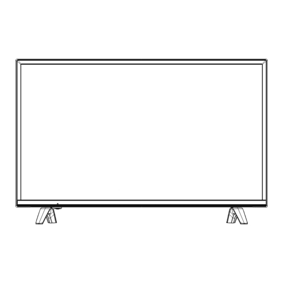
- Page 1 LED Television Model No. TH-43D310Q 5M53A Chassis...
- Page 2 SCHNEIDER ELECTRONICS GMBH-GERMANY 1. CAUTION CA UTION: Use of controls, adjustments or procedures other than those specified herein may result in hazardous radiation exposure. CA UT ION : T O RE DUCE TH E RIS K OF CA U T ION ELECTR ICA L SHOCK, DO NOT RE MOVE COVER (OR BACK).
- Page 3 SCHNEIDER ELECTRONICS GMBH-GERMANY IMPORTANT SAFETY INSTRUCTIONS CAUTION: Read all of these instructions. Save these instructions for later use. Foll ow all W arnings and Instructions marked on the audio equipment. 1. Read Instructions-All the safety and operating instructionsshouldbe read before the productis operated. 2.
- Page 4 SCHNEIDER ELECTRONICS GMBH-GERMANY PROTECTION AND LOCATION OF YOUR SET Do not use this television set near water ... for example, near a bathtub, washbowl, kitchen sink, or laundry tub, in a wet basement, or near a swimming pool, etc. Never expose the set to rain or water. If the set has been exposed to rain or water, unplug the set from the wall outlet and refer servicing to qualified service personnel.
- Page 5 SCHNEIDER ELECTRONICS GMBH-GERMANY OPERATION OF YOUR SET 18. This television set should be operated only from the type of power source indicated on the marking label.If you are not sure of the type of power supply at your home, consult your television dealer or local power company. For television sets designed to operate from battery power, refer to the operating instructions.
- Page 6 PRODUCT SPECIFICATIONS LED TV CATEGORY: 43" LED TV HD MODEL NO: TH-43D310Q REFERENCE MODEL (PANASONIC/COMPETITION): TH-43D310Q Panasonic ASSEMBLER South Africa ID PHOTO REMOTE: Add Picture CHASSIS / Main Board:5M53A PARAMETERS SPECIFICATIONS REMARKS (IF ANY) OSD LANGUAGES ENGLISH MANUAL LANGUAGES ENGLISH...
- Page 7 Factory OSD Manual 1 TO ENTER FACTORY MAIN MENU 1.1 Press AV button and follow with key 3,1,9,5 one by one. 1.2 Factory main menu is as following: 2 ADC ADJUST 2.1 Press ▲/▼ button, choose ADC ADJUST and press OK button to enter. Before adjusting, enter the channel you want to adjust and input adjust signal (YPBPR channel: 576P and 720P with 100% color bar;...
- Page 8 100% color bar tessellated white and black Note: 1、The YPBPR and PC’s Auto White Balance adjust (AUTO ADC) must be done on the product line. 2、In YPBPR channel ,must adjust the SD and HD two modes. 3 White balance Select White balance, go to the “Source” item to select the channel which you want to adjust then select TEMPERATURE (Medium, Warm, Cool).
- Page 9 Press◄/► buttons can adjust the value to the best effect. COPY ALL : Copy the values to all source! 4 Panel Control No adjust. 5 SPECIAL SET FAC. HOTKEY Press◄/► button to switch factory hotkey on or off. For shipping condition, this item should be off.
- Page 10 Adjust the Saturation Curve. Hue Curve Adjust the Hue Curve. Sharpness Curve Adjust the Sharpness Curve. Volume Curve Adjust the Volume Curve. 7 HOTEL FUNCTION No adjust. 8 Other Press OK to set the appropriate EMC values. UART DEBUG Press ► button to set UART DEBUG status. HK for debug, None to turn off debug status. VIF1 No adjust.
- Page 11 8 Software Update(USB) Press OK button to update software from USB. 9 Info Press OK button to show software information. END. V56 Software Upgrade Instruction Upgrade bin file The file name of the upgrade bin is ‘merge.bin’ for USB upgrade. USB upgrade procedures for TV set 1.
- Page 12 ISP Software Upgrade 1 Hardware tools 1.1 USB cable 1.2 USB to serial port tool [driver need to be installed before this tool works: FTC100103(MSTAR)(XP)] 1.3 4PIN to VGA convert cable 2 Connect Connection is shown below:...
- Page 13 3 Driver and Upgrading applications FTC100103(MSTAR) and MSTAR ISP Utility tool. 3.1 Installing driver. A dialog window will pop up when the upgrade tool is connected to computer through usb cable. Choose“Install from a list or specific location (Advanced)”and click“Next” ,another dialog window shows:...
- Page 14 Click “Next” to start installing, there may be a warning as below during this process. In the end a dialog window as below will show up, click “Finish” to finish.
- Page 15 Note: there is three drive to install, so these steps should be repeated for three times. Just follow the messages of the computer, the upgrade tool will not work until the three drives are installed. 3.2 Run ISP tool to upgrade software 3.2.1 Run a Mstar ISP tool such as ‘ISP_Tool_473.exe’.
- Page 16 If connect failed, it will show ‘Can’t Find the Device Type !!’. Note: If it fail to connect, please check: 1, whether power is on. 2, whether the driver is installed successfully and the option Use USB in Config page is available. 3, whether the cable connection is correct.
- Page 17 When it finishes, it looks like A Pass in green will show. It is not recommended to upgrade software by ISP tool because HDCP key will be erased. In this case, HDCP key need to be re-programmed. 3.2.6 HDCP key re-program Follow step 3.2.1 to 3.2.4, switch to HDCP page, load the key file and make settings as following picture.
- Page 18 Switch back to Auto page, make settings as following picture. Partial Erase address must be set to 0x003B0000.
- Page 19 When it finishes, it looks like A Pass in green will show. Hotel Mode Enter Hotel Mode: MENU+7906. Enter Hotel Mode state:...
- Page 20 Hotel Mode Press◄/► button to turn on or turn off hotel mode. Initial INPUT Press◄/► button to switch power on source. Initial POS Only available when Initial INPUT switch to ATV. Press◄/► button to set power on TV channel. Initial VOL Level Press◄/►...
- Page 21 Block Diagram System Block Diagram VLED≈50V Key check point AC INPUT D1D1=12V U0P3/U0P6 5V to 3.3V POWER CONTROL UNIT U0P5 5V to 1.8V U0P7 12V to 5V U0A3 VCC=12V U0P4 5V to 1.15V...
- Page 22 Circuit Block Diagram INTERNAL POWER SUPPLY HD PANEL ME9435A +12V_PANEL +12V AOZ3015 +5V_Standby DC TO DC SPI FLASH AS1117L +3.3V_Standby 32Mbit DC TO DC LVDS SIGNAL AS1117L +1.8V_DDR2 DC TO DC +5V_Stb G5728 VDDC_1.15V DC TO DC USB2.0 AS1117L +5V_Normal +3.3V_TUNER DC TO DC TSUMV56...
- Page 23 Page-02 Function Block INTERNAL POWER SUPPLY FHD PANEL ME9435A +12V_PANEL +12V +5V_Standby DC TO DC SPI FLASH AS1117L +5V_Standby 32Mbit +3.3V_Standby DC TO DC AS1117L +5V_Normal +1.8V_DDR2 DC TO DC +5V_Standby G5728TO1U VDDC_1.15V DC TO DC USB2.0 AS1117L +5V_Normal +3.3V_TUNER DC TO DC MSD3553/V56 HDMI1(MHL3.0)
- Page 24 5V/230mA 1.15V/1000mA G5728 5V/350mA 3.3V_stb/350mA MSD3553 LD1117-3.3 5V_Normal 1.8V_DDR/150mA? LD1117 5V_Normal AMS1117-3.3V 3.3V_TU/200MA 5V/2330mA 12V/1920mA 5V_Normal/3350mA(1750MA) ME2345A AOZ3015 5V_USB/1000mA(500MA) 5V_Normal FUSE STB_EN POWER IN 5Amax 5V_Normal 5V_MHL/2000mA(900MA) G524C3 Istb=16mA VCC_Pannel /1.5A ME9435 12V/3A 12V/1.5A TPA3140D2 MSD3553(5M53N-49E2000) Title Title Title <Title> <Title>...
- Page 25 公版 备注 FUNCTION NAME AV/VGA AUDIO IN-L AV/YUV AUDIO IN-L AUL4 AUR4 AV/VGA AUDIO IN-R AV/YUV AUDIO IN-R AVOUT_L LINEOUTL3 Amplifier Input_L AVOUT_R LINEOUTR3 Amplifier Input_L GPIO44/TX1 GPIO45/RX1 GPIO3 PANEL_ON/OFF PANEL_ON/OFF GPIO1 PWR_ON/OFF PWR_ON/OFF GPIO0/SPDIF_OUT SPDIF_OUT SPDIF_OUT PWM0 BRI_ADJ BRI_ADJ PWM1/MHL_VBUS AMP_MUTE AMP_MUTE...
- Page 26 2015-10-15: 修改KEY1_OUT网络从CN0S2的8PIN到9PIN 2015-10-15: 删除I2S网络无用的测试点 2015-10-15: H1螺钉孔改为4.0 2015-10-15: 修改AMP_MUTE网络 2015-10-15: 修改串口网络 2015-10-21: 增加测试点 2015-10-22: 增加主芯片散热片 2015-10-22: 更改C3M7、C4M9、R0A13封装 2015-11-07: 修改AV左右声道输入问题 2015-11-12: 更改耳机静音电路,解决交流关机冲击声 2015-11--27: 取消耳机运放,修改耳机静音电路 MSD3553(5M53N-49E2000) Title Title Title <Title> <Title> <Title> Size Size Size Document Number Document Number Document Number <Doc> <Doc> <Doc>...
- Page 27 5V Power(option) 3A 5V SWITCH +5V_STB +5V_NOR R3P4 C3P5 Q0P3 AO3401A 47KΩ 100nF R3P6 R2P3 C3P8 100KΩ 100KΩ +12V_PWR +12V_NOR U0P7 ±5% +5V_STB L0P5 PGND 10uH C3P9 CE0P1 NC/100uF AGND COMP R5P6 R2P4 100nF 4.7KΩ ±5% AOZ3015AI C6P7 C6P8 C6P9 20KΩ...
- Page 28 HS0D1 D0D1 D0D2 HEAT SINK S3MB S3MB +42V +42V HS0D3 HEAT SINK L0D7 SUPHV F0D2 100uH T0D1 D0D3 OVP450V 2A/250V D1D9 HBR20150S C3D1 C3D4 C3D5 C3D2 R4D9 470uF 100nF 100nF 470uF 39KΩ MUR460 HS0D2 CN1D3 SUPHV SUPHV D8D1 D8D2 HEAT SINK 1N5408 1N5408 L0D1...
- Page 29 TAS5707 EARPHONE/LINE OUT FB0A4 60Ω/100MHz 22.1KΩ R5A8 R5A9 R6A0 470Ω 470Ω 60Ω/100MHz FB0A3 C7A8 C7A9 C7A7 NC/2.2nF +3.3V_AUDIO +3.3V_AMP 4.7nF 4.7nF C8A1 C8A2 C8A0 1uF F0A3 47nF 47nF 5A/32V +12V_NOR VDD_AMP +3.3V_AUDIO C8A3 33nF L0A7 22uH R6A1 22Ω C8A4 VDD_AMP C8A8 JA0A1 C8A5...
- Page 30 C0B8 R4B2 100pF 10Ω L0D2 LED+ +42V 100uH CN-M LED1- LED1 D0B1 C0B6 C0B7 LED2- LED2 HBR20150S 82uF 82uF LED3- LED3 R6B0 LED4- LED4 LED5 270KΩ LED5- LED6- LED6 BL_VIN +12V_PWR R0B10 R0B11 R0B3 1N4148W R6B1 C3B10 68Ω 68Ω 68Ω D1B11 Q1B0 C0B5...
- Page 31 HDMI HDMI0_RX 0N HDMI0_RX 0N HDMI0_RX 0P HDMI0_RX 0P HDMI0_RX 1N HDMI0_RX 1N HDMI0_RX 1P HDMI0_RX 1P HDMI0_RX 2N HDMI0_RX 2N HDMI0_RX 2P HDMI0_RX 2P HDMI0_CLKN +1.8V/1.5V_DDR HDMI0_CLKN AVDD_DDR_DATA AVDD_DDR_CMD +1.15V_VDDC VDDC AVDDL_DVI DVDD_DDR HDMI0_CLKP HDMI0_CLKP HDMI0_SCL HDMI0_SCL HDMI0_SDA FB203 FB204 HDMI0_SDA HDMI0_HPDIN...
- Page 32 +3.3V_TUNER VDD1V8 R1T5 470KΩ C5T1 C5T2 10nF X0T2 16MHz FAE CAI Modify--2015-09-12 L1T0 33nH C5T9 U0T5 +3.3V_TUNER R9T2 R9T4 C6T4 100nF L2T4 VDD_3p3 CLK_OUT JA0T1 T_SDA M_SDA LNA_INP RF_IN_M M_SCL LNA_INN L1T1 FB0T3 220Ω/100MHz VDD1V8 +3.3V_TUNER VDD_1p8 VDD_IO 100Ω RF SOCKET 330nH C6T7 AGC_2 /GPO_3...
- Page 33 +3.3V_Normal To TCON RIGHT C1N0 NC/1uF CN0N0 CN0N1 ±10% CN-F R2N0 NC/0Ω CN-F LEFT U1N0 GLK1 CLK1 R2N48 GLK2 CLK2 1KΩ R1N3 NC/0Ω CLK1 GLK3 CLK3 VCOM_OP REVERSE GST_A LVB1P1 VOUT CLK2 GLK4 CLK4 R2N2NC/0Ω R2N3NC/0Ω GCLK_A LVB2N1 CLK3 GLK5 CLK5 R2N49 MCLK_A...
- Page 34 POWER_CONNECT +5V_STB BL-ADJUST R0S1 1KΩ BL-ADJUST BRI_ADJ BL-ON/OFF R0S6 1KΩ VBL_CTRL BL_ON/OFF VBL_CTRL R2S9 R0S5 H :ON 4.7KΩ 10KΩ L :OFF C0S1 NC/2.2uF R1S4 200Ω STANDBY PWR_ON/OFF STANDBY PWR_ON/OFF IR&Key_CONNECT +3.3V_Standby +5V_STB +5V_STB R2S4 R1S5 10KΩ NC/10KΩ R2S0 CN0S2 IR_OUT IR-in IR-in LED_OUT...
- Page 35 SZ LVDS Connector RP0L6 0Ω X 4 RP0L1 0Ω X 4 LVDSB1P_O LVB1P1 LVDSA1P_O LVA1P1 LVDSB1N_O LVB1N1 LVDSA1N_O LVA1N1 LVDSB0P_O LVB0P1 LVDSA0P_O LVA0P1 LVDSB0N_O LVB0N1 LVDSA0N_O LVA0N1 RP0L5 0Ω X 4 RP0L2 0Ω X 4 LVDSBCLKP_O LVBCLKP1 LVDSBCLKN_O LVBCLKN1 LVDSB2P_O LVB2P1 LVDSB2N_O LVB2N1...
- Page 36 HDMI1(MHL) HDMI2 HDMI0_RX 2P HDMI0_RX 2P JA0J4 HDMI0_RX 2N HDMI0/5V HDMI0_RX 2N JA0J3 HDMI0_RX 2P HDMI0_RX 1P HDMI3/5V DATA2+ HDMI0_RX 1P MHL_CD_SENSE HDMI3_RX 2P HDMI3-RX 2P HDMI3_RX 2P DATA2 SHIELD DATA2+ HDMI3_RX 2P HDMI0_RX 2N HDMI0_RX 1N HDMI3-RX 2N HDMI3_RX 2N HDMI0_RX 1N HDMI3_RX 2N DATA2-...
- Page 37 Trouble Shooting Terms: IR: Infrared Receiver RC: Remote Control IR logic: IR blink with RC action IR logic: IR blink with RC action LVDS: Low Voltage Differential Signal, output from processor and input for panel O/C: Open Cell, panel with source board BL: Back Light,light source for panel module g,g f p LB: LED (Light Emitting Diode) Bar, light source for BL module VBL: Voltage for Back Light (before Boost)
- Page 38 2.No Display / Black Panel Back light is OK, sound is OK, but no picture. No Display TCON +12V Check TCON Upgrade software LVDS cable OK? Reconnect/ Check TCON Replace LVDS Fuse & MOSFET cable Replace MB/panel Replace MB/panel Check other Cable connection...
- Page 39 3.No back light Power LED logic OK, sound OK, but no picture(Different from No Display). Power LED logic OK, sound OK, but no picture(Different from No Display). No backlight Measure the Voltage of VLED during power on OVP when Always VBL Short LB OVP? disconnect...
- Page 40 4.No sound One or all signal source without sound. No sound Signal source Speaker AMP I2C signal connections Upgrade Check input software Replace/ Defect on AMP signal and reconnect unit terminal speakers Check IC & I2S Replace main signal circuit IC/main board Change signal source and...
- Page 41 5.Signal source no function One or several source no function. Signal no function Signal source no Check LVDS Upgrade Signal source function? connection software Check MCU Check signal Signal source power/crystal source wave form Check other Check terminal settings Change/repair power/signal signal cable wave form...
- Page 42 6.Abnormal Display OSD NG or picture NG. Abnormal Display Check LVDS LVDS cable TCON VCC wave/resistance connection OK? Reconnect/repla Check power MCU NG Upgrade ce LVDS cable flow software Check other Replace main Replace Replace main connections board MCU/main board Replace panel...
- Page 43 7.No tuning channels DTV or ATV no Channels. No tuning channels Tuner power/ Signal setting Upgraded crystal/I2C bus software OK? Change setting/ Check TV Check & replace Replace tuner tune again settings power flow/crystal units IC/MCU Replace signal Tune again Replace main Replace main source...
- Page 44 Disassemble The picture is from design model and may not 100 percent match the final end products, but the operating process is the same. Make sure the wiring will remain the same as you open the TV set, wrong wiring may cause safety issue. Disassemble process...
- Page 45 All electric parts need to handle with ESD measures, ESD glove/ wrist strip/ ESD workstation is requested during repair process. And TV should place on an ESD cloth pad in case of scratch and crack during repair work. Use Rosh solder paste if you want to repair components. 1.
- Page 46 3. remove PCB Pull out the socket connection in red block and remove screws in red circle. Take out the PCB. 4. remove IR/Key PCB You can find IR and key pad in the red box. There is no screw on the IR board, untie the hook structure and take out the PCB. Remove the key pad.
- Page 47 No. Function Function Backlight wire Key pad/IR board/receiver Main board Source board, part of the panel Speaker unit...
- Page 48 VESA assemble process For smaller and medium flat panels, LCD monitors and screens from 12" to 22.9" diagonal, and falling in a weight range up to 30.8 lbs. (14 kg): 75mm x 75 mm or 100 mm x 100 mm (2.95" x 2.95" or 3.94" x 3.94") ...
- Page 49 Step4, VESA assemble When the wall is different, the assemble process is different. When it is bricks, insert expansion screws directly. When it is gypsum board or wooden board, use a wooden stick between VESA and wall, to spread the force to the wood stick touching surface to make safe. Make marks with knife or mark pen on the wall, mount at least 6 expansion screws to hold the VESA.
- Page 51 AC LINE CORD 1500MM 0.75*2 BIG SOUTH AFR TH-43D310Q 43INCH TV 5900-F45131-5010 Left LVDS cable FFC 50 PINS P=0.5MM L=450MM(245+10*2+185 TH-43D310Q 43INCH TV 5900-F35131-5020 Right LVDS cable FFC 50 PINS P=0.5MM L=350MM(220+15*2+100 TH-43D310Q 43INCH TV 53HD-260401-W000 Remote Control Remote Control HS-0401P-00 "PANASONIC" FO TH-43D310Q 43INCH TV...
- Page 52 BOM LIST Part No. Description Q'ty Unit 4900-116052-R000 CRYSTAL 16.000000MHZ HC-49U/S CL:20PF +/ 1 PC 4900-124053-R000 CRYSTAL 24.000000MHZ HC-49U/S CL:20PF +/ 1 PC 5400-921120-0420 WAFER(M) P=2.0MM H-TYPE SINGLE ROW 4 PIN 1 PC 6100-020100-0450 EARPHONE JACK 3.5MM H-TYPE BLACK 1 PC 6100-049100-01C0 RF CONNECTOR (F) H-TYPE 14.2MM D=6.1MM 1 PC...
- Page 53 168P-G4L015-SAK0 (TI) POWER ASS'Y 168P-G4L015-K0 1 ST 5M53A-01SB0X-K0 (TI) MAIN MATCH SCREEN ASS'Y 5M53A-43P21 1 ST 4100-CA0000-T0 SMD RESISTOR 0 OHM 1/10W +/-5% (1.6x0.8M 11 PC 4100-CA0000-T7 SMD RESISTOR 0 OHM 1/16W +/-5% ( 0402 1 13 PC 4100-CA0220-T0 SMD RESISTOR 2.2 OHM 1/10W +/-5% (1.6x0. 1 PC 4100-CA1010-T7 SMD RESISTOR 100 OHM 1/16W +/-5% ( 0402...
- Page 54 4300-CB1050-A200 SMD X5R CERAMIC CHIP CAP. 1UF 10V +/-20% 5 PC 4300-CB2250-7300 SMD X5R CERAMIC CHIP CAP. 2U2F 10V +/-10 2 PC 4300-CB2250-A200 SMD X5R MLCC 2U2F 10V +/-20% (1.0*0.5MM) 2 PC 4300-CC104D-T5 SMD CERAMIC CHIP CAPACITOR 0.1UF 16V +/- 56 PC 4300-CC105D-T2 SMD CERAMIC CHIP CAPACITOR 1UF 16V +/-10...
- Page 55 4876-2833C0-5200 SMD RF CERAMIC INDUCTOR 33NH +/-5% 200MA 2 PC 5400-99112S-0900 SMD WAFER(M) P=1.25MM H-TYPE SINGLE ROW 1 PC 5800-A5M53A-0P00-C MAIN & POWER & DRIVER PCB 210*188*1.6MM 1 PC 6000-300001-00 SMD FUSE 3A/32V (VERY FAST-ACTING) 1 PC 6000-500429-T0 SMD FUSE 5A/32V FAST TIME-TO-TRIP UL/CSA 1 PC 6100-150110-1940 SMD HDMI SOCKET BLACK H-TYPE 19 PIN FOR8...
- Page 56 4144-CD3930-2500 SMD RESISTOR 39K OHM 1/4W +/-1% (3.2 X 1 1 PC 4144-CD4740-T1 SMD RESISTOR 470K 1/4W +/-1% (1206 3.2X 4 PC 4144-CD5140-T1 SMD RESISTOR 510K OHM 1/4W +/-1 3216 TAP 2 PC 4144-CD8240-5500 SMD RESISTOR 820K OHM 1/4W +/-5% 3216 TA 1 PC 4144-CY2040-2300 SMD RESISTOR 200K OHM 1/10W +/-1% (1.6*0...