Table of Contents
Advertisement
Quick Links
Advertisement
Table of Contents

Related Manuals for Bosch Rexroth ctrlX CORE plus X3


Summary of Contents for Bosch Rexroth ctrlX CORE plus X3
- Page 1 Operating Instructions ctrlX CORE plus Controls R911420136, Edition 01...
- Page 2 Copyright © Bosch Rexroth AG 2023 All rights reserved, also regarding any disposal, exploitation, reproduction, editing, distribution, as well as in the event of applications for industrial property rights. Liability The specified data is intended for product description purposes only and shall not be deemed to be a guaranteed characteristic unless expressly stipulated in the contract.
-
Page 3: Table Of Contents
Declaration of conformity ....... . . R911420136, Edition 01 Bosch Rexroth AG... - Page 4 12.4.1 Secure Boot..........34 Bosch Rexroth AG...
- Page 5 16.3 Packaging............40 17 Service and support Index R911420136, Edition 01 Bosch Rexroth AG...
-
Page 6: About This Documentation
Required qualification: Individual who is able to assess the tasks assigned and to identify possible safety risks owing to qualification in the subject, knowledge and experience. The individual should also be familiar with the standards and regulations. Bosch Rexroth AG R911420136, Edition 01... -
Page 7: Scope
Customer requests, comments or suggestions for improvement are of great importance. Please email your feedback on the documentations to Feedback.Documentation@boschrexroth.de. Directly insert ⮫ comments into the electronic PDF document and send the PDF file to Bosch Rexroth. R911420136, Edition 01 Bosch Rexroth AG... -
Page 8: Product Identification And Scope Of Delivery
24 EAC conformity mark 10 Plant number 25 Regulatory Compliance Mark (RCM) 11 Manufacturing date 26 China-RoHs 2 label 12 Part number 27 CCC marking 13 State of revision 28 Name of origin 14 Serial number Bosch Rexroth AG R911420136, Edition 01... -
Page 9: Scope Of Delivery
In case of non-compliance with this safety instruction, death or serious injury WARNING can occur. In case of non-compliance with this safety instruction, minor or moderate CAUTION injury can occur. In case of non-compliance with this safety instruction, material damage can NOTICE occur. R911420136, Edition 01 Bosch Rexroth AG... -
Page 10: Symbols Used
General mechanical engineering • Building automation Danger due to unintended use WARNING The protection specified by Bosch Rexroth cannot be ensured if not used as intended. − Use the product exclusively as intended by Bosch Rexroth. − Operate this device only under the mounting and installation conditions, in the position and under the ambient conditions (temperature, degree of protection, humidity, EMC etc.) specified in this documentation. -
Page 11: Spare Parts, Accessories And Wear Parts
Notes on sensor values: • "0 - 10% of eMMC life time used" means that up to 10 % of the maximum write cycles can be used. • Create a backup if the value exceeds 80%. R911420136, Edition 01 Bosch Rexroth AG... -
Page 12: Ambient Conditions
ESD resistance acc. to DIN EN 61131-2 Criterion B • Test voltage 8 kV for air discharge 4 kV for contact discharge To avoid vibration, secure the cables at a short distance (< 20 cm). ① Bosch Rexroth AG R911420136, Edition 01... -
Page 13: Technical Data
Communication interfaces RJ-45 • 3 × Ethernet connection (10 Mbit, 100 Mbit, 1 Gbit) 1 × USB host, TYPE C (USB2.0), maximum cable length of 3 m SD card Slot for SD card Battery CR1025 R911420136, Edition 01 Bosch Rexroth AG... -
Page 14: Voltage Supply And Current Consumption
Voltage dips at current supply interfaces PS1 < 1 ms, evaluation criterion A Electrical isolation DC 707 V (not evaluated by UL) 24 V supply (U GND) to the functional earth 24 V supply (U GND) to the functional earth Bosch Rexroth AG R911420136, Edition 01... -
Page 15: Standards
Partie 2: Spécifications et essais des équipements DIN EN 60529 Schutzarten durch Gehäuse (IP-Code) 2014 – Degrees of protection provided by enclosures (IP Code) – Degrés de protection procurés par les enveloppes (Code IP) R911420136, Edition 01 Bosch Rexroth AG... -
Page 16: Ce Marking
Normes génériques – Immunité pour les environnements industriels DIN EN 61000-6-4 Elektromagnetische Verträglichkeit (EMV) September 2011 Teil: 6-4: Fachgrundnormen – Störaussendung für Industrie- bereiche Normes génériques – Norme sur l’émission pour les environ- nements industriels Bosch Rexroth AG R911420136, Edition 01... -
Page 17: Ul/Csa Certified
Loss of EU conformity due to modifications at the device EU marking applies only to the device upon delivery. After modifying the device, verify the EU conformity. For the CE declaration of conformity, go to the Bosch Rexroth media directory: ⮫ www.bos- chrexroth.com/MediaDirectory, search term "DCTC-30455-001". -
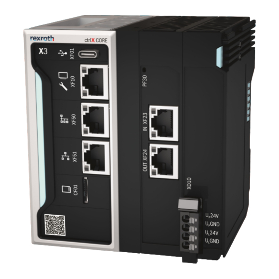
Page 18: Interfaces
➁ XF10 Ethernet RJ45 socket RJ45 plug 10/100/1000 MBit 8-pin (twisted pair, 8-wire) HMI and engineering port ➂ XF50 Ethernet RJ45 socket RJ45 plug 10/100/1000 MBit 8-pin (twisted pair, 8-wire) Field bus master (Ethercat) Bosch Rexroth AG R911420136, Edition 01... -
Page 19: Local Bus Interface Ethercat Of Ctrlx Core
, only the current consumption of the infeed terminal and the I/O modules. For the integration into the parent system, the respective ESI files are available. For the ESI files, go to http://www.boschrexroth.com/electrics. ⮫ R911420136, Edition 01 Bosch Rexroth AG... - Page 20 (Only the current consumption of the infeed terminal (typ. 50 mA) and the I/O modules (3 A max.) is measured. In addition to the transferred measured value, the ctrlX CORE consumes more than shown here. PLUS Word 4 Undervoltage Overvoltage Overcurrent Undervoltage Overvoltage Overcurrent 6-15 Reserved Bosch Rexroth AG R911420136, Edition 01...
-
Page 21: Mounting, Dismounting And Electric Installation
CORE 21 / 46 plus Housing dimensions Mounting, dismounting and electric installation 10.1 Housing dimensions 117.5 Fig. 5: Front view ① Optional Fig. 6: Side view R911420136, Edition 01 Bosch Rexroth AG... -
Page 22: Installation Notes
To ensure air cooling in the device by convection, mount the control only vertically on a horizontal support rail as shown in the following figure. In the shown mounting position, the natural convection supports the forced cooling air flow. Heat pockets can thus not be caused in the device. Bosch Rexroth AG R911420136, Edition 01... - Page 23 In case of a several line design, the supply air has to be measured under each line and its limit value may not be exceeded. For information on ambient temperatures, refer to ⮫ Chapter 6.1 “Ambient conditions of the ctrlX CORE” on page R911420136, Edition 01 Bosch Rexroth AG...
-
Page 24: Mounting The Control
Control not fixed due to clamped support arm mounting! NOTICE Before mounting, ensure that the support arm mounting of the control is not in open position. If required, release the clamping of the open position using the locking lever, see Figure Bosch Rexroth AG R911420136, Edition 01... -
Page 25: Mounting The Ctrlx I/O Module
There is an endcover on the right upon delivery. Remove this endcover to connect the modules in series. Position the endcover on the last module of the station to protect it against short circuit and contamination. R911420136, Edition 01 Bosch Rexroth AG... -
Page 26: Dismounting The Control
⮫ Chapter 11.2.1 “Notes on safe decommissioning” on page Removing the control from the support rail Remove the left or the right end clamp. Remove the first ctrlX IO terminal from the ctrlX CORE if required. plus Bosch Rexroth AG R911420136, Edition 01... -
Page 27: Electric Installation
All lines of the 24 V voltage supply have to be routed separately from lines carrying higher voltages. All peripherals, such as digital sensors or actuators connected to the interfaces of the control, also have to comply with the criteria of safety-separated circuits. R911420136, Edition 01 Bosch Rexroth AG... -
Page 28: Power Connector Xd10
Use only cables approved for temperatures of at least 60°C. • Use freely routed 1-wire cables. The wire distance has to be at least the wire diameter. • The stripping length is 8 mm. Bosch Rexroth AG R911420136, Edition 01... -
Page 29: Voltage Supply
U and GND U feeding as well as U and GND U feeding does not damage the device. However, the control does not start and the status displays are not on. R911420136, Edition 01 Bosch Rexroth AG... -
Page 30: Grounding
(e.g. at the load power supply unit). Hence, the supply current circuit is a PELV circuit. 10.5.4 Grounding Failure due to insufficient grounding NOTICE An optimum grounding is required to impede possible interferences from the control and to discharge them to the ground. Bosch Rexroth AG R911420136, Edition 01... -
Page 31: Shielding
Mount the control. For details, refer to ⮫ Chapter 10.2 “Installation notes” on page Connect the voltage supply to the XD10 connection of the control. Refer to ⮫ Chapter 10.5.2 “Power connector XD10 ” on page R911420136, Edition 01 Bosch Rexroth AG... -
Page 32: Safe Decommissioning
An SD card can be used to load an image to the control. All existing data is deleted when loading a new image. Please contact the Bosch Rexroth Service. Please back up the user data before you delete it if you want to restore it on another control. -
Page 33: Status Display At The Power Connector Xd10 Ctrlx Core Plus
See R911386579. ⮫ 12.2.5 Status display of device status LED For the status displays of the device status LED of the infeed terminal, refer to the bus coupler documentation, see R911416731. ⮫ R911420136, Edition 01 Bosch Rexroth AG... -
Page 34: Initial Firmware
12.4.1 Secure Boot Booting is secured by "Secure Boot". Thus, it can only be loaded by a runtime system released by Bosch Rexroth. For the kernel development, this mechanism can be unlocked using an app and the respective license. -
Page 35: Sd Card
The battery is used to buffer the real-time clock if the control is disconnected from voltage. A circuit monitors the battery state. For notes on changing the battery, see ⮫ Chapter 14.3 “Battery change ” on page A discharged battery causes an incorrect system time. R911420136, Edition 01 Bosch Rexroth AG... -
Page 36: License Information
(ii) in case of code licensed under the GPL v3 for as long as Bosch Rexroth offers spare parts or customer support for that product. Error causes and troubleshooting 13.1... -
Page 37: Maintenance
Ensure that the IP degree of protection remains unchanged during mainte- nance! Only the maintenance works at the device listed in this chapter are permitted. For further information in the event of repair, please contact the Bosch Rexroth Service. 14.2 Scheduled maintenance tasks Include the following tasks into the maintenance schedule: •... -
Page 38: Ordering Information
Thus, variants with individual ordering information result from the required functional scope. Please contact the corresponding marketing organization and ask for the ordering information of the control variant optimized for your application. Bosch Rexroth AG R911420136, Edition 01... -
Page 39: Type Code
Subject to export control (EU) No export license required ....................= N Special variante None ............................. = NN Robert Bosch ......................... = B1 Fig. 16: Type code 15.3 Accessories and spare parts For ordering information on accessories and spare parts, refer to the chapter “Spare parts, accessories and wear parts”. -
Page 40: Disposal
Furthermore, the products returned for disposal must not contain any undue foreign substances or external components. Send the products free of charge to the following address: Bosch Rexroth AG Bürgermeister-Dr.-Nebel-Straße 2 97816 Lohr a.Main Germany 16.3... -
Page 41: Service And Support
Detailed description of malfunction and circumstances • Type plate specifications of the affected products, in particular type codes and serial numbers • Your contact data (phone and fax number as well as your e-mail address) R911420136, Edition 01 Bosch Rexroth AG... -
Page 42: Index
EMV........16 Enabling bootloader..... . 34 Bosch Rexroth AG R911420136, Edition 01... - Page 43 Stranded cable......28 Stripping length......28 R911420136, Edition 01 Bosch Rexroth AG...
- Page 44 44 / 46 ctrlX CORE plus Bosch Rexroth AG R911420136, Edition 01...
- Page 45 CORE 45 / 46 plus R911420136, Edition 01 Bosch Rexroth AG...
- Page 46 Bosch Rexroth AG Bgm.-Dr.-Nebel-Str. 2 97816 Lohr a.Main Germany Tel. +49 9352 18 0 Fax +49 9352 18 8400 www.boschrexroth.com/electrics R911420136 R911420136...