Table of Contents
Advertisement
Advertisement
Table of Contents

Related Manuals for Bosch ECU MS 25 Sport


Summary of Contents for Bosch ECU MS 25 Sport
- Page 1 Engine Control Uni MS 25 Sport Manual Version 1.0 12/03/2019...
-
Page 2: Table Of Contents
Communication PC to device ..................................MS 25 Sport programming....................................Initial Data Application....................................... 3 Peripherals ..................................4 Getting Started................................5 Engine Performance Calibration ........................... 6 Bosch Motorsport support ............................7 Wiring Harness................................ii / 40 Engine Control Unit MS 25 Sport Bosch Motorsport... -
Page 3: Technical Data
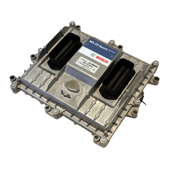
Technical data | 1 1 Technical data The ECU MS 25 Sport engine control unit manages common rail Diesel engines with solenoid valve injectors up to 8 cylinders. The MS 25 Sport utilizes software development process based on MATLAB® & Simulink®. -
Page 4: Application
1 | Technical data 1.2 Application Installation Notes Communication Ordering Information Engine Control Unit MS 25 Sport F 02U V0U 800-02 4 / 40 Engine Control Unit MS 25 Sport Bosch Motorsport... -
Page 5: Pin Layout
Technical data | 1 Mechanical Drawing 1.3 Pin Layout The pin layout is also placed at Bosch Motorsport Homepage. Some pins and functions are optional and not included in the base version of the MS 25 Sport software. Bosch Motorsport Engine Control Unit MS 25 Sport 5 / 40... - Page 6 O_S_RL19 GPU2 LS General purpose output 2 (LS) O_T_RL06 GPU1 LS General purpose output 1 (LS) O_T_RL05 InjectorPwrStg 1 + InjectorPwrStg 1 "bank1" O_P_SVH11 InjectorPwrStg 4 + InjectorPwrStg 4 "bank1" O_P_SVH12 6 / 40 Engine Control Unit MS 25 Sport Bosch Motorsport...
- Page 7 Ground for turbocharger speed 2 (Inductive) G_R_DF05 turbospeed1+ Turbocharger speed 1 (Inductive) I_F_DF04POS nturbo1 turbospeed1- Ground for turbocharger speed 1 (Inductive) I_F_DF04NEG LSU heat+ Battery plus output 22 O_V_RH22 Bosch Motorsport Engine Control Unit MS 25 Sport 7 / 40...
- Page 8 Wheel sens. Gnd. Front Wheel Sensor Ground Front G_R_DF01 aps1 supply +5V Accelerator pedal supply 1 V_V_5VSS2D 5V sens. Supply 4 Sensor Supply 4 V_V_5VSS2A 5V sens. Supply 2 Sensor Supply 2 V_V_5VSS1D 8 / 40 Engine Control Unit MS 25 Sport Bosch Motorsport...
-
Page 9: Input Channels
– More metal-to-metal contact is better Connection of the power supply The following notations for power signals are used: – Term 15 is a switched battery rail controlled by the Engine On-switch. Bosch Motorsport Engine Control Unit MS 25 Sport 9 / 40... -
Page 10: Trigger Wheel
1.7 Trigger Wheel The software assumes a toothed trigger wheel for proper operation. The number of the teeth is hard coded by Bosch Motorsport and can’t be changed by the customer. Custom gap teeth numbers are optional. We recommend 60 (-2) teeth as shown in the following picture. The crank wheel trigger sensor must be an inductive type for the default configuration, Hall-effect crank sensor is optional and requires software change. - Page 11 The procedure for correct adjustment of the trigger wheel is described in the drawing on the next page. Procedure to find the right position for the crank and cam trigger Rotate the engine to the precise position of TDC compression for cylinder #1 Bosch Motorsport Engine Control Unit MS 25 Sport 11 / 40...
- Page 12 The Hall effect signal may be the inversion of its cam trigger: the tooth effects a “low” sig- nal at the sensor and vice versa for other trigger wheel configurations the indicated values may vary. 12 / 40 Engine Control Unit MS 25 Sport Bosch Motorsport...
-
Page 13: Starting Up The Ecu
2 Starting up the ECU 2.1 Installation of software tools PC tools and ECU programs for the MS 25 Sport are available at Bosch Motorsport homepage for free download. – RaceCon version 2.5.3.0 or later: used for system configuration, data application and online measurement. - Page 14 Drag the ECU icon with pressed left mouse click on the vehicle view, then a dialog opens Now the ECU program archive PST files must be selected. These archives are delivered by Bosch or are available at Bosch Motorsport homepage. Specify the MS 25 Sport program archive: MS25_SPORT_XX_XXX_X_RaceCon_CCP_VL1.pst...
- Page 15 If in the project tree and main display area MS 25 Sport icon is shown as >red< it means that the software in the device differs from what is in the RaceCon project. Bosch Motorsport Engine Control Unit MS 25 Sport...
- Page 16 In the project tree if the MS 25 Sport is shown as >yellow<, means the firmware of the MS 25 Sport device and project are identical, but the data is different. 16 / 40 Engine Control Unit MS 25 Sport Bosch Motorsport...
- Page 17 ECU data can be read to RaceCon project (upload data from the device). MS 25 Sport is shown as >green<, means firmware and data of the device and the project are now identical. Bosch Motorsport Engine Control Unit MS 25 Sport 17 / 40...
- Page 18 Transfer error occurred, device memory full. Click on the option → Create HEX file from the working page and flash the device. RaceCon automatically saves the hex file and starts pro- gramming 18 / 40 Engine Control Unit MS 25 Sport Bosch Motorsport...
- Page 19 Dialog window opens for selection of calibration variables to be exported as parameter file. Existing parameter file can be used as filter to select same variables automatically as in that existing file. Bosch Motorsport Engine Control Unit MS 25 Sport 19 / 40...
- Page 20 In case of porting calibration from older software with differences on table sizes etc., it is important to pay attention if all values can be im- ported properly. 20 / 40 Engine Control Unit MS 25 Sport Bosch Motorsport...
- Page 21 Complete ECU calibrations can also be saved and opened as HEX-files. This works fine within same software version projects if no ECU software (program archive/a2l) is changed. HEX-files can be saved or opened in the Project tree … … or under Calibration/Measuring view. Bosch Motorsport Engine Control Unit MS 25 Sport 21 / 40...
-
Page 22: Initial Data Application
Wheel for basic one teeth motorsport cam trigger and see calibration guidelines for more help on calibrating different Diesel OEM type cam wheels. Calibration example for 60-2 crank and simple one teeth cam wheel 22 / 40 Engine Control Unit MS 25 Sport Bosch Motorsport... - Page 23 Bosch Motorsport Engine Control Unit MS 25 Sport 23 / 40...
- Page 24 Energizing time map must be known for the used injector and nozzle and should be calib- rated for the entire operation range of rail pressure. Using wrong energizing time map may end in unexpected engine torque behavior and can cause serious engine damage. 24 / 40 Engine Control Unit MS 25 Sport Bosch Motorsport...
- Page 25 PRV mounted directly in the fuel rail is only designed to open and protect the system very few times during its life time, which must be considered in rail pressure setpoint map calibration. Rail pressure control calibration parameters Bosch Motorsport Engine Control Unit MS 25 Sport 25 / 40...
- Page 26 (Engine On –switch off, wait 30 sec) to store the learned values in the EEPROM. CWAPSADJ=0 no action CWAPSADJ=1 Calibrate first point (0 %) CWAPSADJ=2 Calibrate second point (100 %) 26 / 40 Engine Control Unit MS 25 Sport Bosch Motorsport...
- Page 27 The main limitation curve where the correction factors listed above are applied is CL_QT- LIM, which limits the maximum injection quantity for given engine speed. Low and high idle governors can also affect the injection quantity and engine torque out- put. Bosch Motorsport Engine Control Unit MS 25 Sport 27 / 40...
- Page 28 CL_NLICO_NOM_BAS, which defines the setpoint value as function of engine temperature tmot. If the engine friction map calibration is changed within the low idle setpoint operating range, correct low idle controller behavior must be checked. 28 / 40 Engine Control Unit MS 25 Sport Bosch Motorsport...
- Page 29 There is also a step limiter for ramping up and down when transitioning from start to running mode. Engine speed transitions from start to normal running mode happen based on the NMOT- COND function calibration. Bosch Motorsport Engine Control Unit MS 25 Sport 29 / 40...
- Page 30 Post1 injection is not calculated as a torque generating injection in the software and its timing should be late enough to not produce torque. See Injection System [} 31] for de- tailed explanation of injection timing. 30 / 40 Engine Control Unit MS 25 Sport Bosch Motorsport...
- Page 31 Main injection is always the highest priority. Injection naming and order with base timing and quantity calibration parameters are ex- plained in the picture below. All injection timing parameters are referenced to top dead center (TDC). Bosch Motorsport Engine Control Unit MS 25 Sport 31 / 40...
- Page 32 Post1 (PO1) injection is not calculated as torque generating injection and is not included in the total injection quantity setpoint calculation qfqsc. Timing before TDC is positive and after is negative. 32 / 40 Engine Control Unit MS 25 Sport Bosch Motorsport...
-
Page 33: Peripherals
TD”function”. If a sensor error is set, the output is switched to the default value “function”_DEF. Pressure measurements The system offers many different pressure channels, please see function description Input Signal Processing for details. For gradient and offset information please contact the sensor manufacturer. Bosch Motorsport Engine Control Unit MS 25 Sport 33 / 40... - Page 34 3 | Peripherals Example oil pressure sensor: 34 / 40 Engine Control Unit MS 25 Sport Bosch Motorsport...
- Page 35 The system offers many different temperature channels, please see function description Input Signal Processing for details. Sensor linearization curves for temperature sensors are applied directly as resistance for each temperature point. Example engine temperature sensor: Bosch Motorsport Engine Control Unit MS 25 Sport 35 / 40...
-
Page 36: Getting Started
Please retain this manual for your records. Before starting Before starting your engine for the first time, install the complete software. Bosch Motor- sport software is developed for Windows operation systems. Read the manual carefully and follow the application hints step by step. -
Page 37: Engine Performance Calibration
The cylinder pressure indication system is a stand-alone sys- tem and this it is not part of the MS 25 Sport system provided by Bosch. If recommenda- tions for a cylinder pressure system are needed, please contact Bosch Motorsport for fur- ther information. -
Page 38: Bosch Motorsport Support
– Engine management system technical definition: engine control unit/ sensors/actu- ator selection and delivery within a wide portfolio including series production and sample parts Feel free to contact your local Bosch Motorsport support team for further information. 38 / 40 Engine Control Unit MS 25 Sport... -
Page 39: Wiring Harness
Wiring Harness | 7 7 Wiring Harness Bosch Motorsport Engine Control Unit MS 25 Sport 39 / 40... - Page 40 Bosch Engineering GmbH Motorsport Robert-Bosch-Allee 1 74232 Abstatt Germany www.bosch-motorsport.com...