Siemens SIMATIC IPC647E Operating Instructions Manual
Hide thumbs
Also See for SIMATIC IPC647E:
- Operating instructions manual (200 pages) ,
- Installation manual (9 pages)
Table of Contents
Advertisement
Quick Links
SIMATIC IPC647E
SIMATIC
Industrial PC
SIMATIC IPC647E
Operating Instructions
09/2022
A5E52254141-AA
Preface
Product description
Safety instructions
Installing and connecting
the device
Commissioning the device
Operating the device
Expanding and assigning
parameters to the device
Device maintenance and
repair
Technical specifications
Dimension drawings
Standards and approvals
Hardware description
Technical support
Markings and symbols
1
2
3
4
5
6
7
8
9
10
A
B
C
Advertisement
Table of Contents

Related Manuals for Siemens SIMATIC IPC647E


Summary of Contents for Siemens SIMATIC IPC647E
- Page 1 SIMATIC IPC647E Preface Product description SIMATIC Safety instructions Installing and connecting the device Industrial PC SIMATIC IPC647E Commissioning the device Operating the device Operating Instructions Expanding and assigning parameters to the device Device maintenance and repair Technical specifications Dimension drawings...
- Page 2 Note the following: WARNING Siemens products may only be used for the applications described in the catalog and in the relevant technical documentation. If products and components from other manufacturers are used, these must be recommended or approved by Siemens. Proper transport, storage, installation, assembly, commissioning, operation and maintenance are required to ensure that the products operate safely and without any problems.
-
Page 3: Preface
• Service and maintenance of industrial PCs General knowledge in the field automation control engineering is recommended. Range of validity of these operating instructions These operating instructions are valid for all order versions of the SIMATIC IPC647E. History Currently released versions of these operating instructions:... - Page 4 Siemens' products and solutions undergo continuous development to make them more secure. Siemens strongly recommends that product updates are applied as soon as they are available and that the latest product versions are used. Use of product versions that are no longer supported, and failure to apply the latest updates may increase customers' exposure to cyber threats.
-
Page 5: Table Of Contents
Safety instructions on transport and storage............... 38 Safety instructions for assembly ..................40 Safety instructions on ambient and environmental conditions ..........42 Safety instructions for I/O devices ..................44 Safety instructions on device and system extensions ............46 SIMATIC IPC647E Operating Instructions, 09/2022, A5E52254141-AA... - Page 6 Installing the hardware RAID adapter card ................76 5.4.2.3 Configuring the hardware RAID system ................79 5.4.2.4 Monitor hardware RAID system with "maxView Storage Manager"........81 5.4.3 Data synchronization in the RAID system ................84 SIMATIC IPC647E Operating Instructions, 09/2022, A5E52254141-AA...
- Page 7 Installation options for drives with drive cage type B............123 6.6.2.2 Removing and installing the 3.5" drive in the drive bay ............. 125 6.6.3 Removing and installing a 2.5" drive (internal) via drive cage ..........128 6.6.4 Install M.2 NVMe SSD....................... 130 SIMATIC IPC647E Operating Instructions, 09/2022, A5E52254141-AA...
- Page 8 Technical specifications of the expansion card slots ............162 Technical specifications of the hardware RAID adapter card ..........168 8.10 Technical specifications of graphic ................... 168 8.11 Technical specifications of the NVIDIA A2 Tensor Core GPU..........170 SIMATIC IPC647E Operating Instructions, 09/2022, A5E52254141-AA...
- Page 9 Exclusive PCI hardware interrupt ..................187 System resources ......................188 A.4.1 Currently allocated system resources ................188 A.4.2 I/O address allocation ....................... 188 A.4.3 Interrupt assignments ...................... 189 A.4.4 Memory address assignments ..................191 SIMATIC IPC647E Operating Instructions, 09/2022, A5E52254141-AA...
- Page 10 Markings and symbols ........................197 Overview ......................... 197 Symbols for safe use and disposal ..................197 Symbols for operator controls ..................197 Symbols of certificates and approvals ................198 Interface icons ......................... 199 Index ..............................200 SIMATIC IPC647E Operating Instructions, 09/2022, A5E52254141-AA...
-
Page 11: Product Description
• Link and QR code to the online form for the quality control noti- • Supplied data storage medium fication in the SIEMENS After Sales Information System (ASIS) • Operating Instructions of the de- vice • Installation of the device •... - Page 12 Backup and recovery of files, di- SIMATIC IPC Image & Partition rectories, drive partitions Creator (https://support.industry.siemens. com/cs/de/de/view/109780775) SIMATIC NET Industrial communication • Online at: SIMATIC NET (http://w3.siemens.com/mcms/au tomation/en/industrielle-kommu- nikation/Seiten/Default.aspx) See also SIMATIC IPC Image & Partition Creator (https://support.industry.siemens.com/cs/de/en/view/109780775) SIMATIC IPC647E Operating Instructions, 09/2022, A5E52254141-AA...
-
Page 13: Product Highlights
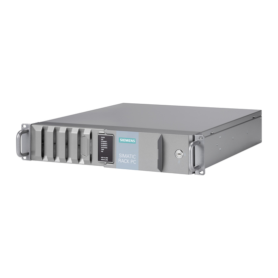
Product description 1.2 Product highlights Product highlights The SIMATIC IPC647E is a high-performance industrial PC in 19" installation format (2 U). It is perfectly suited for PC applications with high-level industry functionality. Device view Note Depending on the configuration ordered the features and illustrations described in this manual may differ from the features of your device. - Page 14 – All components inside the device can only be accessed when front door is open • Device monitoring through operating displays on the front for Ethernet; alarms for fans, temperature, Watchdog and drives in RAID1 systems SIMATIC IPC647E Operating Instructions, 09/2022, A5E52254141-AA...
-
Page 15: Scope Of Application
The SIMATIC IPC has CE certification for use in the industrial sector as well as in residential and commercial areas and small businesses. In addition to the industrial applications, therefore, it can also be used in building automation or in public facilities. SIMATIC IPC647E Operating Instructions, 09/2022, A5E52254141-AA... -
Page 16: External Design Of The Device
(locked by front door) ② System status displays (Page 27) ③ Front door: lockable, protection against unauthorized access ④ Lock • Key vertical: open • Key horizontal: closed ⑤ 19" mounting bracket with handle SIMATIC IPC647E Operating Instructions, 09/2022, A5E52254141-AA... - Page 17 Drive cage (in this case type A); depending on the expansion variant, see: • Drive cage type A (Page 18) • Drive cage type B (Page 20) ④ Interfaces on the front of the device, see Device ports (Page 22) SIMATIC IPC647E Operating Instructions, 09/2022, A5E52254141-AA...
-
Page 18: Drive Cage Type A
Mounting location 2 (internal) for: • 2.5" drive internal via drive cage Mounting location 3 (internal) for: • 2.5" drive internal via drive cage Cover Removable tray or blanking panel (if no removable tray present) SIMATIC IPC647E Operating Instructions, 09/2022, A5E52254141-AA... - Page 19 Components of the removable tray Status display (Page 29) Status display (Page 29) Number of the mounting location (here: Mounting location 0) Lock See also Installation options for drives with drive cage type A (Page 114) SIMATIC IPC647E Operating Instructions, 09/2022, A5E52254141-AA...
-
Page 20: Drive Cage Type B
Mounting location 2 (internal) for: • 2.5" drive internal via drive cage Mounting location 3 (internal) for: • 2.5" drive internal via drive cage Cover See also Installation options for drives with drive cage type B (Page 123) SIMATIC IPC647E Operating Instructions, 09/2022, A5E52254141-AA... -
Page 21: Rear Of The Device
③ Connections of the optional graphics card (here: NVIDIA Quadro P400 graphics card) ④ Fixing screws for strain relief (Page 64) ⑤ Range: Device ports (Page 22) ⑥ Power supply (here: redundant power supply) SIMATIC IPC647E Operating Instructions, 09/2022, A5E52254141-AA... -
Page 22: Connections
SuperSpeed backwards compatible to USB 3.0 / 2.0 / 1.1; each 900 mA / high current Sum of the currents on the USB interfaces of the device (including the internal USB interfaces) ≤ 3 A SIMATIC IPC647E Operating Instructions, 09/2022, A5E52254141-AA... - Page 23 Maximum cable length: max. 3 m; depending on attenuation of the cable and maximum data rate of the connection. Use the original connection technology of the I/O devices to be connected without adapters and without extensions. SIMATIC IPC647E Operating Instructions, 09/2022, A5E52254141-AA...
-
Page 24: Power Supply Connections
You can find information on the optional graphics cards under "Technical specifications of graphic (Page 168)". 1.4.5.2 Power supply connections Sockets for power plugs with single and redundant power supply Single power supply (400 W) Redundant power supply (350 W) SIMATIC IPC647E Operating Instructions, 09/2022, A5E52254141-AA... -
Page 25: Operator Controls
On-off button and Reset button for single and redundant power supply The on-off button ① and the reset button ② are located on the front of the device behind the front door. ① On/off button ② Reset button SIMATIC IPC647E Operating Instructions, 09/2022, A5E52254141-AA... - Page 26 The alarm reset button is only available for devices with redundant power supply and it is simultaneously the status display of the redundant power supply (Page 29). Use the alarm reset button to switch off the signal tone of the redundant power supply in the event of an error. SIMATIC IPC647E Operating Instructions, 09/2022, A5E52254141-AA...
-
Page 27: Status Displays
No data traffic ⑤ ETHERNET 3 GREEN Data traffic ⑥ WATCHDOG Watchdog status Not activated GREEN Activated Expired ⑦ TEMP Temperature status No error Possible causes: • CPU temperature is critical • Device temperature is critical SIMATIC IPC647E Operating Instructions, 09/2022, A5E52254141-AA... -
Page 28: Status Display Of The Ethernet Interface
The numbering by the operating system may deviate from this. Status display Status Meaning of the status LED 1 10 Mbps Lit green 100 Mbps Lit orange 1000 Mbps LED 2 Connection exists Flashes Activity SIMATIC IPC647E Operating Instructions, 09/2022, A5E52254141-AA... -
Page 29: Status Display Of Redundant Power Supply
Power supply not connected • No drive installed GREEN • Device is switched on and a drive is installed ② Activity Status of the drive ORANGE • Drive is active • Drive is not active SIMATIC IPC647E Operating Instructions, 09/2022, A5E52254141-AA... -
Page 30: Internal Construction Of The Device
2 parts mounted on the connecting rail ⑩ Heat sink of the processor, connected by 2 heat pipes with heat exchanger of the processor ⑪ Bus board ⑫ Slot for expansion cards on the bus board SIMATIC IPC647E Operating Instructions, 09/2022, A5E52254141-AA... -
Page 31: Accessories And Replacement Parts
Accessories and replacement parts 1.6.1 Hardware accessories Accessories from Siemens are available for your device. These are not included in the scope of delivery. Obtaining accessories from the SIEMENS Industry Mall You can find additional information in the online ordering system Industry Mall (https://mall.industry.siemens.com). - Page 32 Mini DisplayPort to DVI-D available as single-pack or 3-pack 1 unit 6ES7648-3AJ00-0XA0 • mDP-DP adapter* 3 units 6ES7648-3AJ00-1XA0* Mini DisplayPort to DisplayPort available as single-pack or 3-pack * Part of the optional graphics card P400 SIMATIC IPC647E Operating Instructions, 09/2022, A5E52254141-AA...
- Page 33 Product description 1.6 Accessories and replacement parts SIEMENS spare parts services You can find information on ordering, the provision and delivery of spare parts under "Industry Online Support: Spare parts services (http://support.automation.siemens.com/WW/view/en/16611927)". Name Description Article number Filter set Rack PC 2HM...
-
Page 34: Software Accessories
More detailed information on software products for SIMATIC IPCs • Catalog and ordering system for Automation and Drives: Industry Mall (https://mall.industry.siemens.com) • Industrial automation technology portfolio: Products & Services (https://new.siemens.com/global/en/products/automation.html) SIMATIC IPC647E Operating Instructions, 09/2022, A5E52254141-AA... -
Page 35: Safety Instructions
Touching these areas or components can cause death or serious physical injury. • Always disconnect the cabinet from the mains before opening it. • Ensure that the power to the control cabinet cannot be turned on accidentally. SIMATIC IPC647E Operating Instructions, 09/2022, A5E52254141-AA... - Page 36 "Switching off the device (Page 66)". • Do not touch power cables and data transmission cables during a thunderstorm. • Keep sufficient distance from electric cables, distributors, systems, etc. SIMATIC IPC647E Operating Instructions, 09/2022, A5E52254141-AA...
- Page 37 Validate the correct functioning of the plant to avoid functional restrictions. Use in industrial environments Note Use in an industrial environment without additional protective measures This device was designed for use in a normal industrial environment according to IEC 60721-3-3. SIMATIC IPC647E Operating Instructions, 09/2022, A5E52254141-AA...
-
Page 38: Safety Instructions On Transport And Storage
A damaged device has unpredictable properties and states. Death or serious injury could occur. • Avoid installing and commissioning a damaged device. • Label the damaged device and keep it locked away. Send off the device for immediate repair. SIMATIC IPC647E Operating Instructions, 09/2022, A5E52254141-AA... - Page 39 • Allow the device to warm up to room temperature before commissioning. • Do not expose the device to direct heat radiation from a heating device. • If condensation develops, wait approximately 12 hours or until the device is completely dry before switching it on. SIMATIC IPC647E Operating Instructions, 09/2022, A5E52254141-AA...
-
Page 40: Safety Instructions For Assembly
There is a risk of overheating and personal injury. Note the following instructions and information under: • "Climatic and mechanical and ambient conditions (Page 159)" • "Safety instructions on ambient and environmental conditions (Page 42)" SIMATIC IPC647E Operating Instructions, 09/2022, A5E52254141-AA... - Page 41 Touching these areas or components can cause death or serious physical injury. • Always disconnect the cabinet from the mains before opening it. • Ensure that the power to the control cabinet cannot be turned on accidentally. SIMATIC IPC647E Operating Instructions, 09/2022, A5E52254141-AA...
-
Page 42: Safety Instructions On Ambient And Environmental Conditions
• When the device is operated in severe environments which are subject to caustic vapors or gases, ensure sufficient clean air is provided. • Clean the enclosure surface with a damp cloth. • Make sure that no water gets inside the device. SIMATIC IPC647E Operating Instructions, 09/2022, A5E52254141-AA... - Page 43 • Remove radiation sources from the environment of the device. • Switch off radiating devices. • Reduce the radio output of radiating devices. • Read the information on electromagnetic compatibility. • Read the information in the technical specifications. SIMATIC IPC647E Operating Instructions, 09/2022, A5E52254141-AA...
-
Page 44: Safety Instructions For I/O Devices
• Switch off the affected device and then insert the power plug. • Connect all cables from the system to the device and switch all components of the system to active before starting the measurement. SIMATIC IPC647E Operating Instructions, 09/2022, A5E52254141-AA... - Page 45 • For control cabinet mounting: Use a central, easily accessible AC circuit breaker, especially when close to the device. • When you install the device, make sure that the power supply connector is easily accessible. SIMATIC IPC647E Operating Instructions, 09/2022, A5E52254141-AA...
-
Page 46: Safety Instructions On Device And System Extensions
• For control cabinet mounting: Use a central, easily accessible AC circuit breaker, especially when close to the device. • When you install the device, make sure that the power supply connector is easily accessible. SIMATIC IPC647E Operating Instructions, 09/2022, A5E52254141-AA... - Page 47 Improperly carried out repairs or extensions to the device can lead to property damage or danger to the users. If you install or exchange system expansions and damage your device, the warranty becomes void. SIMATIC IPC647E Operating Instructions, 09/2022, A5E52254141-AA...
- Page 48 • UL approval of the device only applies when the UL-approved components are used according to their "Conditions of Acceptability". • We are not liable for functional limitations caused by the use of third-party devices or components. SIMATIC IPC647E Operating Instructions, 09/2022, A5E52254141-AA...
-
Page 49: Installing And Connecting The Device
On the supplied data storage medium (read only) you will find: • Software and tools to recover your ordered Microsoft® Windows® operating system • Device drivers for installation in operating systems • Quick Install Guide for SIMATIC IPC647E • Operating instructions for SIMATIC IPC647E • Product information •... - Page 50 (Page 34) Printed documents • Quick Install Guide SIMATIC IPC647E with link and QR code to the online form for quality control (quality control notification) in the SIEMENS After Sales Information System (ASIS) • Product Information "Important notes on your device"...
-
Page 51: Checking The Delivery Package
If the contents of the package are incomplete, damaged or do not correspond to your order, you can use the After Sales Information System (ASIS) (http://siemens.com/asis) to provide feedback on product deliveries and repairs. Complete the online form for quality control (quality control notification). -
Page 52: Device Identification Data
The following illustrations are examples. The data of your device may differ from the data in these examples. Rating plate The rating plate is located inside the front door. Example: SIMATIC IPC647E nameplate (the information on the nameplate is device-specific) Identification data of the device ① QR code for information about the device ②... - Page 53 The COA label is only available for devices delivered with Microsoft® Windows® operating system installed. Example: COA label for the Microsoft® Windows® 10 operating system (the data of the product key are grayed out in the figure) SIMATIC IPC647E Operating Instructions, 09/2022, A5E52254141-AA...
-
Page 54: Mounting The Device
Horizontal: Mounting on device base This installation type meets the requirements in accordance with IEC60297-3-100. Additional information You can find additional information in the Quick Installation Guide (QIG) that is enclosed with the device. SIMATIC IPC647E Operating Instructions, 09/2022, A5E52254141-AA... -
Page 55: Securing Device
You can find the dimensions for the holes under: "Dimension drawing for drill holes for telescopic rails (Page 176)". You can find detailed information on the drives under: "Technical specifications of the telescopic rails (Page 172)". SIMATIC IPC647E Operating Instructions, 09/2022, A5E52254141-AA... -
Page 56: Connecting The Device
The power supply cord and the plug connector must bear the prescribed markings. SIMATIC IPC647E Operating Instructions, 09/2022, A5E52254141-AA... -
Page 57: Connection Of Equipotential Bonding Line
• The permissible rated voltage of the device must match the local supply voltage. • Operate the device only in grounded power supply networks (TN networks in accordance with VDE 0100 Part 100 or IEC 60364-1). • Operation via non-grounded or impedance-earthed networks is prohibited. SIMATIC IPC647E Operating Instructions, 09/2022, A5E52254141-AA... - Page 58 4. Switch the device on using the on/off switch (position |). 5. To prevent unintentional removal of the power plug, secure the power plug on the device. To do this, screw on the power plug interlock ② with the fixing screw ①. SIMATIC IPC647E Operating Instructions, 09/2022, A5E52254141-AA...
-
Page 59: Connecting A Redundant Power Supply (Ac)
• For control cabinet mounting: Use a central, easily accessible AC circuit breaker close to the device, if possible. Requirement • You have observed the information under "Country-specific information on supply voltage (Page 56)". • T10 screwdriver SIMATIC IPC647E Operating Instructions, 09/2022, A5E52254141-AA... - Page 60 (Page 25)". 5. To prevent unintentional disconnection of the power plug, secure the power plug on the device. To do this, screw on the two power plug interlocks ② with the fixing screws ①. SIMATIC IPC647E Operating Instructions, 09/2022, A5E52254141-AA...
-
Page 61: Connecting I/O Devices
1. Connect the I/O devices to the respective interfaces. You can find information on the position of the interfaces in "Device ports (Page 22)". 2. Secure the cables (Page 64) with a strain relief. SIMATIC IPC647E Operating Instructions, 09/2022, A5E52254141-AA... -
Page 62: Connecting Several Monitors (Multi-Monitoring)
(X70) Monitor 1 DP (DisplayPort) Monitor 2 DP (DisplayPort) Monitor 3 DP (DisplayPort) Monitor 4 DP (DisplayPort) Monitor 5 DP (DisplayPort) Monitor 6 DP (DisplayPort) via adapter, see "Hardware accessories" Labeling on the device SIMATIC IPC647E Operating Instructions, 09/2022, A5E52254141-AA... -
Page 63: Connecting The Device To Networks
Control level. Additional information is available under SIMATIC NET (http://w3.siemens.com/mcms/automation/en/industrial- communications/Pages/Default.aspx). The software package and the documentation are not included in the scope of delivery Additional information You can find additional information on the Internet at: Technical support (https://support.industry.siemens.com/cs/us/en/) SIMATIC IPC647E Operating Instructions, 09/2022, A5E52254141-AA... -
Page 64: Securing The Cables
2. Screw the strain relief ① to the device using the fastening screws ②. 3. Insert detachable cable ties into corresponding holes of the strain relief and secure the cable with the cable ties. SIMATIC IPC647E Operating Instructions, 09/2022, A5E52254141-AA... -
Page 65: Commissioning The Device
The minimum downtime required for the supply voltage depends on the configuration of the device. Configure this function with the firmware setting: • State After G3 You can find information on this in the firmware/BIOS description, see "Important instructions and manuals for operating the device (Page 11)". SIMATIC IPC647E Operating Instructions, 09/2022, A5E52254141-AA... -
Page 66: Switching Off The Device
• Then pull out the mains plug or operate the central AC circuit breaker when installing in a control cabinet. Therefore, when installing the device in a control cabinet, ensure that the AC circuit breaker is easily accessible. SIMATIC IPC647E Operating Instructions, 09/2022, A5E52254141-AA... - Page 67 – To switch the device on again, press the on/off button again. Hardware reset with reset button: • Press the reset button. – The device switches off and on again. Information on the position of the buttons is available under "Operator controls (Page 25)". SIMATIC IPC647E Operating Instructions, 09/2022, A5E52254141-AA...
-
Page 68: Operating The Device
You can find information on the position of the connection sockets and the labeling on the device in section "Device ports (Page 22)". To connect several monitors to the device at the same time (Page 62)(multi-monitoring), you can install a so-called "optional graphics card" (Page 112). SIMATIC IPC647E Operating Instructions, 09/2022, A5E52254141-AA... -
Page 69: Drive Configurations
• Drive cage type B (Page 20) Mounting locations for drives in the hardware RAID system The 2 hard disks required for a hardware RAID system can be installed in the following locations: • Drive cage type A (Page 18) SIMATIC IPC647E Operating Instructions, 09/2022, A5E52254141-AA... -
Page 70: System With 2 Drives
You have the option of backing up your data to this drive. You can find information on how to boot the device from the second drive in the detailed firmware/BIOS description, see "Important instructions and manuals for operating the device (Page 11)". SIMATIC IPC647E Operating Instructions, 09/2022, A5E52254141-AA... -
Page 71: Raid Systems
3. Use the arrow keys of the keyboard to select "Device Management" from the firmware selection menu and confirm your selection. To select and save settings, refer to the information on navigating in the firmware, see above. SIMATIC IPC647E Operating Instructions, 09/2022, A5E52254141-AA... - Page 72 1. Select Start > Intel® Optane™ Memory and Storage Management. 2. Select the "Manage" tab. You can find information on configuring a RAID system with "Intel® Optane™ Memory and Storage Management" in the documentation or help for the software. SIMATIC IPC647E Operating Instructions, 09/2022, A5E52254141-AA...
-
Page 73: Monitoring The Onboard Raid System With "Intel® Optane™ Memory And Storage Management
• Insert only a brand new drive or a drive that is configured as a replacement drive. • Refer to the controller documentation for instructions on setting up replacement drives. 1. Select "Start" > "Intel® Optane™ Memory and Storage Management". 2. Select the "Manage" menu. SIMATIC IPC647E Operating Instructions, 09/2022, A5E52254141-AA... - Page 74 Configure the mounted drive under "Create Raid Volume". Mount new drive during operation in the onboard RAID system (after an error has occurred) Requirements The system is configured to mount new drives manually (not automatically), see above. SIMATIC IPC647E Operating Instructions, 09/2022, A5E52254141-AA...
- Page 75 4. From the drive information, select the "Mark as spare" function ③. The drive is mounted to the onboard RAID system and appears in the mounted drives area. See also Data synchronization in the RAID system (Page 84) SIMATIC IPC647E Operating Instructions, 09/2022, A5E52254141-AA...
-
Page 76: Hardware Raid System
If you want to operate your device as a hardware RAID system afterwards, install a hardware RAID adapter card. Requirement • Device with drive cage type A • 4 GB main memory SIMATIC IPC647E Operating Instructions, 09/2022, A5E52254141-AA... - Page 77 Operating the device 5.4 RAID systems • T10 screwdriver • Components for installing the hardware RAID adapter card. Your local SIEMENS contact person will provide you with information on these components. ① Capacitor block with capacitor block line ② Hardware RAID adapter card, see "Technical specifications of the hardware RAID adapter card (Page 168)"...
- Page 78 8. Connect the power supply of the drives (SATA power, 15-pin) to the backplane of the corresponding removable tray, see "Installing a backplane for removable tray (Page 118)". 9. Close the device. 10.Configure the installed hardware RAID adapter card. SIMATIC IPC647E Operating Instructions, 09/2022, A5E52254141-AA...
-
Page 79: Configuring The Hardware Raid System
1. Switch on the device or restart it. 2. To access the firmware user interface, press and hold down the <Esc> key immediately after switching on the device, as soon as the SIEMENS logo and the message "Press ESC for boot options" appear. - Page 80 11.Under "Logical Drive Label", enter a name for your RAID system. 12.Select [Submit Changes] to save your settings. The message "Logical Drive Creation Successful" is displayed in the next window. 13.Select [Back to Main Menu]. SIMATIC IPC647E Operating Instructions, 09/2022, A5E52254141-AA...
-
Page 81: Monitor Hardware Raid System With "Maxview Storage Manager
Then install the website security certificate. Requirement • 4 GB main memory • The operating system is restarted. • The operating system is protected with a user name and password • You have administrator rights SIMATIC IPC647E Operating Instructions, 09/2022, A5E52254141-AA... - Page 82 The Certificate Export wizard opens. 7. Select "Next". 8. In the following window, the desired format is "DER-coded...". Do not change this setting. 9. Select "Next". 10.Assign a name and save the security certificate. SIMATIC IPC647E Operating Instructions, 09/2022, A5E52254141-AA...
- Page 83 Monitor hardware RAID system with "maxView Storage Manager" You can find detailed information on the use of "maxView Storage Manager" in the user guide to the software, see "Software and documentation for the hardware RAID system (Page 76)". SIMATIC IPC647E Operating Instructions, 09/2022, A5E52254141-AA...
-
Page 84: Data Synchronization In The Raid System
Guide value for the duration of data synchronization: • < 3h at 90% HDD system load In addition, system performance may be limited in the case of a manually started maintenance operation until completion of the maintenance phase. SIMATIC IPC647E Operating Instructions, 09/2022, A5E52254141-AA... -
Page 85: Monitoring Of The Device
(RAID state) • The following statuses, for example, • The status of an inactive hot swap drive is not dis- are displayed in a RAID system: played. "Normal", "OK", "Degraded", "Error Rebuild", "Rebuilding" SIMATIC IPC647E Operating Instructions, 09/2022, A5E52254141-AA... - Page 86 • SIMATIC IPC DiagBase (Page 87) for monitoring and alarm output locally on the device • SIMATIC IPC DiagMonitor (Page 87) for monitoring and alarm output via the network SIMATIC DiagBase or SIMATIC DiagMonitor also controls the status displays of the IPC, see: System status displays (Page 27). SIMATIC IPC647E Operating Instructions, 09/2022, A5E52254141-AA...
-
Page 87: Simatic Ipc Diagbase
Information on the software and documentation of SIMATIC IPC DiagMonitor can be found under: • Important instructions and manuals for operating the device (Page 11) Note SIMATIC IPC DiagMonitor only supports the device hardware as of version 5.1.5. Older versions do not support the device hardware. SIMATIC IPC647E Operating Instructions, 09/2022, A5E52254141-AA... -
Page 88: Remote Maintenance Of The Device
A SIMATIC IPC can be booted remotely from a bootable ISO file made available by another PC. Device requirements for remote maintenance The following requirements must be fulfilled in order to use the remote maintenance: • Processor that supports iAMT technology • Connection to the network SIMATIC IPC647E Operating Instructions, 09/2022, A5E52254141-AA... -
Page 89: Remote Maintenance With Intel® Amt
4. Assign the "Enabled" value to the firmware setting "AMT BIOS Features". 5. Press the button <F10> (Save & Exit) and confirm the subsequent dialogue with <Y>. 6. Switch off the device and then configure the Intel® AMT functions (Page 90). SIMATIC IPC647E Operating Instructions, 09/2022, A5E52254141-AA... -
Page 90: Configuring Intel® Amt
– A lower case letter – Eine Zahl – A special character . ! @ # $ % ^ & * Note The underscore and blank space are valid password characters but do not increase password complexity. SIMATIC IPC647E Operating Instructions, 09/2022, A5E52254141-AA... - Page 91 When a user attempts to establish a KVM connection remotely, a six-digit number is displayed on the AMT PC. The remote user must enter this number on the help desk PC before the KVM connection can be opened. SIMATIC IPC647E Operating Instructions, 09/2022, A5E52254141-AA...
-
Page 92: Reset Intel® Amt Functions To Default Settings And Disabling Iamt
One effect of resetting to the default settings is that Intel® AMT is disabled. 1. Switch on the device or restart it. 2. To access the firmware user interface, press the <Esc> button several times in succession immediately after switching on the device. SIMATIC IPC647E Operating Instructions, 09/2022, A5E52254141-AA... -
Page 93: Disabling Intel® Amt Access To The Firmware/Bios Settings
4. Assign the "Disabled" value to the firmware setting "AMT BIOS Features". 5. Press the button <F10> (Save & Exit) and confirm the subsequent dialog with <Yes>. 6. Switch off the device and then configure the Intel® AMT functions. SIMATIC IPC647E Operating Instructions, 09/2022, A5E52254141-AA... -
Page 94: Trusted Platform Module (Tpm)
• Always observe the respective import restrictions of the country in which the device will be used. Activating the Trusted Platform Module You can find information on activating the Trusted Platform Module in the detailed firmware/BIOS description in "Important instructions and manuals for operating the device (Page 11)". SIMATIC IPC647E Operating Instructions, 09/2022, A5E52254141-AA... -
Page 95: Ai Unit Nvidia A2
The AI Unit NVIDIA A2 consists of the NVIDIA A2 Tensor Core GPU① and a fan② that are installed in an enclosure③. Requirements Note When a SIMATIC IPC647E with AI Unit NVIDIA A2 is delivered, the device is configured according to the system requirements. • Operating system: – Microsoft® Windows® 10 Enterprise 2019 LTSC, 64-bit –... - Page 96 5.8 AI Unit NVIDIA A2 Firmware setting when using the AI Unit NVIDIA A2 For SIMATIC IPC647E devices with AI Unit NVIDIA A2, the firmware setting "Fan Control Mode" is assigned the value "Enhanced" at the time of delivery. This value must not be changed.
-
Page 97: Expanding And Assigning Parameters To The Device
3. Open the front door (Page 68)①. 4. Open the fan cover ②. 5. Unscrew the locking screw of the enclosure cover ③. 6. Slide the enclosure cover back ④. 7. Lift up and remove the enclosure cover. SIMATIC IPC647E Operating Instructions, 09/2022, A5E52254141-AA... -
Page 98: Installing And Removing Expansion Cards
3. Remove the 4 screws ① with which the bus frame is mounted in the device. 4. Pull the bus frame carefully and evenly upwards out of the device at the marked points ②. When doing this, do not tilt the bus frame. SIMATIC IPC647E Operating Instructions, 09/2022, A5E52254141-AA... - Page 99 5. Turn the bus frame over and place it on the device with the bottom side facing up. 6. Unlock the power supply plug and disconnect it. See also Structure of the bus board (Page 184) Components of the bus frame (Page 184) SIMATIC IPC647E Operating Instructions, 09/2022, A5E52254141-AA...
-
Page 100: Installing Expansion Cards
• For low expansion cards: – Retainer, latchable – Retainer guide – Expanding rivets Included in the accessory pack of the device or can be ordered as a replacement part, see "Hardware accessories (Page 31)". SIMATIC IPC647E Operating Instructions, 09/2022, A5E52254141-AA... - Page 101 3. Remove the blanking plate at the position where you want to install the expansion card. To do this, loosen the screw and be sure to keep it because you will need it later. SIMATIC IPC647E Operating Instructions, 09/2022, A5E52254141-AA...
- Page 102 8. Push a latching retainer ③ through one of the guide slots of the mounting bracket until the recess of the retainer carefully engages with the expansion card. Note Latching retainers can only be moved in the direction of the expansion card and snap into place at the corresponding position. SIMATIC IPC647E Operating Instructions, 09/2022, A5E52254141-AA...
- Page 103 Expanding and assigning parameters to the device 6.2 Installing and removing expansion cards 9. Cut off the protruding part of the latching retainerr so that no excess material protrudes. 10.Install the bus frame in the device. 11.Close the device. SIMATIC IPC647E Operating Instructions, 09/2022, A5E52254141-AA...
-
Page 104: Removing Expansion Cards
2. Remove the center rail of the bus frame on the side where the expansion card you want to remove is plugged in. 3. Remove the screw that secures the expansion card to the rear of the device. Save the screw for the installation of a blanking plate. SIMATIC IPC647E Operating Instructions, 09/2022, A5E52254141-AA... - Page 105 4. Remove the expansion cards without tilting from the slot 5. If you do not install a new expansion card after removing the expansion card, install a slot blanking plate at the sampling point using the screw previously removed. SIMATIC IPC647E Operating Instructions, 09/2022, A5E52254141-AA...
-
Page 106: Installing And Removing Memory Modules
4 GB / 8 GB / 16 GB 4 GB / 8 GB / 16 GB / 128 GB 32 GB 32 GB / 32 GB 32 GB Only use memory modules with identical memory capacity per slot. SIMATIC IPC647E Operating Instructions, 09/2022, A5E52254141-AA... - Page 107 • In faults occur, it may be enough to remove one or two memory modules or use a memory module with less capacity so that the physical memory set up on the motherboard and the reserved memory on the expansion card do not overlap. SIMATIC IPC647E Operating Instructions, 09/2022, A5E52254141-AA...
-
Page 108: Installing Memory Modules
3. If necessary, remove the bus frame (Page 98). 4. Open the two locks to the left and right of the slot. 5. Remove the memory module from its packaging. Hold it by the upper edges only. SIMATIC IPC647E Operating Instructions, 09/2022, A5E52254141-AA... - Page 109 7. To prevent tilting, press evenly on both sides of the memory module until both interlocks audibly engage. 8. If necessary, re-install the bus frame. 9. Close the device. Display of a changed memory configuration A changed memory allocation is automatically recognized when the device is switched on. SIMATIC IPC647E Operating Instructions, 09/2022, A5E52254141-AA...
-
Page 110: Removing Memory Modules
Remove the memory module from the slot. 5. If necessary, re-install the bus frame. 6. Close the device. Display of a changed memory configuration A changed memory allocation is automatically recognized when the device is switched on. SIMATIC IPC647E Operating Instructions, 09/2022, A5E52254141-AA... -
Page 111: Connecting A Usb Stick To The Internal Interface
3. Screw the guide rail of the retainer into the enclosure as shown in the figure. 4. Plug in the USB stick. 5. Slide the retainer in the direction of the USB stick. 6. Fix the retainer by turning the screw on the guide rail. SIMATIC IPC647E Operating Instructions, 09/2022, A5E52254141-AA... -
Page 112: Installing And Removing An Optional Graphics Card
(Page 172)". The technical conditions of the power supply must be complied with. 2. Check the firmware settings. 3. Configure the function "Multi-monitoring" in the firmware settings of the device. Note the following information. SIMATIC IPC647E Operating Instructions, 09/2022, A5E52254141-AA... -
Page 113: Removing The Optional Graphics Card
(Page 11)". Procedure 1. The optional graphics card is an expansion card. Remove the optional graphics card. Note the information under "Removing expansion cards (Page 104)". 2. Check the firmware settings. SIMATIC IPC647E Operating Instructions, 09/2022, A5E52254141-AA... -
Page 114: Installing And Removing Drives
• Mounting location 0 • Removing and installing a 2.5" drive (internal) via drive • Mounting location 1 cage (Page 128) Above the drive cage, with drive mounting brackets: • Mounting location 2 (internal) SIMATIC IPC647E Operating Instructions, 09/2022, A5E52254141-AA... -
Page 115: Change 2.5" And 3.5" Drive In Removable Tray
When you remove the drive while data is being written to it, you may damage the drive and destroy data. • Only remove the removable tray from the device when the drive is inactive, see "Status displays on removable tray for drives (Page 29)". SIMATIC IPC647E Operating Instructions, 09/2022, A5E52254141-AA... - Page 116 8. Fasten the new drive with the screws to the base of the removable tray. Only use the original screws. 9. Carefully insert the removable tray into the drive cage of the device again. SIMATIC IPC647E Operating Instructions, 09/2022, A5E52254141-AA...
- Page 117 Ensure that the removable tray fits tightly in the drive cage. 11.Close the tray bracket. 12.Lock the removable tray with the key. Note The removable tray must always be locked to ensure reliable operation of the devices with removable trays. SIMATIC IPC647E Operating Instructions, 09/2022, A5E52254141-AA...
-
Page 118: Installing A Backplane For Removable Tray
Procedure 1. Fully disconnect the device from the line voltage, see "Switching off the device (Page 66)". 2. Open the device. Be sure to follow the important instructions under "Open the device (Page 97)". SIMATIC IPC647E Operating Instructions, 09/2022, A5E52254141-AA... - Page 119 6. On the front of the drive cage, remove the cover of the mounting locations ③, which may be located to the right of the cover ②. 7. Remove all existing removable trays until the drive cage is freely accessible. SIMATIC IPC647E Operating Instructions, 09/2022, A5E52254141-AA...
- Page 120 10.Insert the cover ② into the front of the device. 11.At the backplane, connect the data cables with the corresponding interfaces on the motherboard or the hardware RAID controller. 12.Connect the power supply. 13.Close the device. SIMATIC IPC647E Operating Instructions, 09/2022, A5E52254141-AA...
-
Page 121: Removing A Backplane For Removable Tray
2. Note the assignment of all data cables to the motherboard and disconnect all data cables ①. 3. Unlock the backplane by pressing firmly in the direction of the arrow on the latching lugs ② and press the ejector ③. SIMATIC IPC647E Operating Instructions, 09/2022, A5E52254141-AA... - Page 122 Expanding and assigning parameters to the device 6.6 Installing and removing drives 4. Remove the unlatched backplane board ④ by turning it upwards from the brackets and removing it from the drive cage. 5. Close the device. SIMATIC IPC647E Operating Instructions, 09/2022, A5E52254141-AA...
-
Page 123: Installing Drives In The Drive Cage Type B
• Mounting location 0 • Removing and installing a 2.5" drive (internal) via drive • Mounting location 1 cage (Page 128) Above the drive cage, with drive mounting brackets: • Mounting location 2 (internal) SIMATIC IPC647E Operating Instructions, 09/2022, A5E52254141-AA... - Page 124 1 drive Drive type Ambient temperature +0 to +45 °C 2.5" SATA 2 drives 3.5" SATA 2 drive Drive type Ambient temperature +5 to +35 °C 2.5" SATA 1 drive 3.5" SATA Enterprise 2 drives SIMATIC IPC647E Operating Instructions, 09/2022, A5E52254141-AA...
-
Page 125: Removing And Installing The 3.5" Drive In The Drive Bay
To do this, press down the marked area with a suitable object (e.g. with a screwdriver) until the cover on the drive cage is released. 3. Remove the cover from the front of the device. SIMATIC IPC647E Operating Instructions, 09/2022, A5E52254141-AA... - Page 126 5. Unlock the drive by pressing the two clips ② inwards at the same time. The drive automatically slides out at the front of the device. 6. Pull the drive out of the drive bay. 7. Remove the drive rails ③ on both long sides of the drive. SIMATIC IPC647E Operating Instructions, 09/2022, A5E52254141-AA...
- Page 127 5. Replace the cover on the front of the device. To do this, first hang the cover with the right side in the notches provided. Then close the cover on the left. 6. Close the device. SIMATIC IPC647E Operating Instructions, 09/2022, A5E52254141-AA...
-
Page 128: Removing And Installing A 2.5" Drive (Internal) Via Drive Cage
1. Remove the marked screws. 2. Remove the drive with the mounting brackets. 3. Pull off the cables from the drive as shown. 4. Remove the mounting bracket on the sides of the drive. SIMATIC IPC647E Operating Instructions, 09/2022, A5E52254141-AA... - Page 129 7. Place the drive in the opening at the top of the drive cage. The notches on the mounting brackets point upwards, i.e. the top of the drive points towards the drive cage. 8. Screw the mounting bracket to the top of the drive cage using the 4 screws previously removed. SIMATIC IPC647E Operating Instructions, 09/2022, A5E52254141-AA...
-
Page 130: Install M.2 Nvme Ssd
Make sure that the contacts of the direct connector of the M.2 NVMe SSD remain completely free. 6. Insert the M.2 NVMe SSD ③ slightly diagonally from above into the direct connector socket on the first riser card. SIMATIC IPC647E Operating Instructions, 09/2022, A5E52254141-AA... - Page 131 Fix the M.2 NVMe SSD to the notch at the end of the M.2 NVMe SSD with the pan head screw. Tighten the pan head screw without tension. 9. Re-install the riser card with the M.2 NVMe SSD. (Page 100) 10.Re-install the bus frame. 11.Close the device. SIMATIC IPC647E Operating Instructions, 09/2022, A5E52254141-AA...
-
Page 132: Device Maintenance And Repair
Component Replacement interval Drives 3 years Backup battery 5 years Front fan 3 years Filter mat of the fan (front fan) Depending on the degree of soiling SIMATIC IPC647E Operating Instructions, 09/2022, A5E52254141-AA... -
Page 133: Removing And Installing Hardware
1. Open the front door ① at least by an angle of approx. 45°. 2. Reach into the recessed grip ② of the fan cover. 3. Open the fan cover in the direction of the arrow and remove it. SIMATIC IPC647E Operating Instructions, 09/2022, A5E52254141-AA... -
Page 134: Change The Filter Mat Of The Front Fan
1. Fully disconnect the device from the line voltage, see "Switching off the device (Page 66)". 2. Remove the fan cover. (Page 133) 3. Slide the fan support a bit to the left and move it forward from the front of the enclosure. SIMATIC IPC647E Operating Instructions, 09/2022, A5E52254141-AA... - Page 135 10.Re-insert the small fan cable connectors ② into the larger adapter connectors ③ until they click into place. 11.Replace the fan support with the new fans on the front panel. 12.Replace the fan cover on the front panel. SIMATIC IPC647E Operating Instructions, 09/2022, A5E52254141-AA...
-
Page 136: Changing The Backup Battery
You can find information on configuring the firmware settings in the firmware description, see "Important instructions and manuals for operating the device (Page 11)". • You have observed the local regulations relating to the disposal of used batteries. SIMATIC IPC647E Operating Instructions, 09/2022, A5E52254141-AA... - Page 137 3. Remove expansion cards if necessary, see "Removing expansion cards (Page 104)". 4. Remove the battery from socket. 5. Insert the new battery into the base with slight pressure. 6. Close the device. 7. Check the firmware settings. SIMATIC IPC647E Operating Instructions, 09/2022, A5E52254141-AA...
-
Page 138: Replacing The Single Power Supply
3. Disconnect the cables from the drives and the motherboard. 4. Remove the cable ties securing the power cables in the enclosure. 5. Remove the two screws from the mounting bracket that secures the power supply to the bottom of the enclosure. SIMATIC IPC647E Operating Instructions, 09/2022, A5E52254141-AA... - Page 139 12.Connect the cables to the drives and the motherboard. 13.Use cable ties to reattach the power supply cables to the enclosure. 14.Close the device. 15.Check the safe state of the device. 16.Switch on the power supply. SIMATIC IPC647E Operating Instructions, 09/2022, A5E52254141-AA...
-
Page 140: Changing The Module Of The Redundant Power Supply
7. Plug the power cord into the socket of the newly inserted module ③. 8. Check the safe state of the device. 9. Switch the module on again using the on/off switch ② and make sure that the status display is working correctly. SIMATIC IPC647E Operating Instructions, 09/2022, A5E52254141-AA... -
Page 141: Changing The Enclosure Of The Redundant Power Supply (Ac)
3. Remove both modules of the redundant power supply (Page 140). 4. Turn the screws on the marked positions with the short Phillips screwdriver. 5. Loosen the screws marked in the following picture at the enclosure bottom. SIMATIC IPC647E Operating Instructions, 09/2022, A5E52254141-AA... - Page 142 16.Fasten the cables with cable ties. 17.Now, slide the enclosure all the way to the back and fix it in the appropriate locations with the screws. 18.Re-insert the two modules of the redundant power supply and close the device. SIMATIC IPC647E Operating Instructions, 09/2022, A5E52254141-AA...
-
Page 143: Replacing The Processor
3. Remove the heat sink of the processor. You can find information on the position of the heat sink in "Internal construction of the device (Page 30)". 4. Unlock the socket and lift the socket cover. SIMATIC IPC647E Operating Instructions, 09/2022, A5E52254141-AA... - Page 144 6. Place the new processor in the socket. Note the arrow on the processor when positioning. 7. Lock the processor in place. 8. Install the heat sink of the processor again. 9. Close the device. SIMATIC IPC647E Operating Instructions, 09/2022, A5E52254141-AA...
-
Page 145: Replacing The Ai Unit Nvidia A2
AI Unit NVIDIA A2 later, attach the fan cable to the very same components. 4. Remove the bus frame. To do this, perform all steps completely as described in section: "Remove the bus frame (Page 98)". SIMATIC IPC647E Operating Instructions, 09/2022, A5E52254141-AA... - Page 146 Observe the following when positioning the AI Unit NVIDIA A2: – Position the direct connector of the AI Unit ② at the corresponding slot of the piggyback of the bus board, see "Technical specifications of the expansion card slots (Page 162)". SIMATIC IPC647E Operating Instructions, 09/2022, A5E52254141-AA...
- Page 147 Ensure that the fan cable is fastened so that it is reliably kept away from the area of the fan opening. To do so, fasten the fan cable tightly in the device. By doing so, you prevent blocking the fan or damaging the cable. 10.Close the device. SIMATIC IPC647E Operating Instructions, 09/2022, A5E52254141-AA...
-
Page 148: Replacing The Fan And Nvidia A2 Tensor Core Gpu Of The Ai Unit Nvidia A2
• You have removed the AI Unit NVIDIA A2 from the device. You can find information on this in the section "Replacing the AI Unit NVIDIA A2 (Page 145)". Components of the AI Unit NVIDIA A2 SIMATIC IPC647E Operating Instructions, 09/2022, A5E52254141-AA... - Page 149 5. Guide the fan cable through the cutout at the top frame of the closed side of the enclosure. 6. Close the enclosure with the 7 screws (included in the scope of supply). See also AI Unit NVIDIA A2 (Page 95) SIMATIC IPC647E Operating Instructions, 09/2022, A5E52254141-AA...
-
Page 150: Replacing The Motherboard
4. Remove the processor. (Page 143) 5. Note the assignment of all cables to the motherboard. 6. Disconnect all cables from the motherboard. 7. Remove the connection sockets COM1 and DVI-D at the rear of the device. (Page 22) SIMATIC IPC647E Operating Instructions, 09/2022, A5E52254141-AA... - Page 151 16.Reconnect the device to the supply voltage and switch on the device. 17.Update the firmware settings to match the new motherboard version. Please note during the update whether you are operating a device with or without a RAID system. SIMATIC IPC647E Operating Instructions, 09/2022, A5E52254141-AA...
-
Page 152: Installing Operating System, Software And Drivers
Note If your device no longer boots, for example, after operating system crash during a firmware update, contact your local SIEMENS contact person. Backing up data and changing partitions Use the "SIMATIC IPC Image & Partition Creator" software to back up data under Windows®, see "Important instructions and manuals for operating the device (Page 11)". -
Page 153: Technical Specifications
Redundant power supply (350 W, AC): • 2 × 100 V to 240 V (-15%; +10%) Transient overvoltages Device is designed for connection to supply with overvoltage category II (Transient overvoltages up to 2500 V) SIMATIC IPC647E Operating Instructions, 09/2022, A5E52254141-AA... - Page 154 ≤ 270 W with 85% efficiency Power loss, heat emission Single power supply (400 W): • 260 W = 260 J/s = 0.25 BTU/s Redundant power supply (350 W): • 270 W = 270 J/s = 0.26 BTU/s SIMATIC IPC647E Operating Instructions, 09/2022, A5E52254141-AA...
- Page 155 Only for protected installation. Ensure that the installation opening for the device is splash-proof in areas which may be subject to splash water. See also Safety instructions on ambient and environmental conditions (Page 42) SIMATIC IPC647E Operating Instructions, 09/2022, A5E52254141-AA...
-
Page 156: Current And Power Requirements And Power Supply
The accumulated power of the +5 V and + 3.3 V voltage may be max. 190 W with a single power supply (400 W) and max. 100 W with the redundant power supply (350 W). 3 A for 10 seconds SIMATIC IPC647E Operating Instructions, 09/2022, A5E52254141-AA... - Page 157 The tripping characteristic of the higher-level protection must take into account the starting currents of both the IPC and the other devices. SIMATIC IPC647E Operating Instructions, 09/2022, A5E52254141-AA...
-
Page 158: Technical Specifications Of The Single Power Supply (400 W)
The total output of the +5 V and +3.3 V voltage must be ≤ 100 W. Observe the total power of all voltages permissible for the device, see section "General technical specifications (Page 153)". The total current of the +12 V voltage must be ≤ 25 A. SIMATIC IPC647E Operating Instructions, 09/2022, A5E52254141-AA... -
Page 159: Electromagnetic Compatibility
Tested according to IEC 60068-2-78; IEC 60068-2-30 Operation 5% to 85% at 30 °C; no condensation Gradient: ≤ 10 K/h; no condensation Storage/transport 5% to 95% at 25 to 55 °C; no condensation Gradient: ≤ 20 K/h; no condensation SIMATIC IPC647E Operating Instructions, 09/2022, A5E52254141-AA... - Page 160 • Installation options for drives with drive cage type A (Page 114) • Installation options for drives with drive cage type B (Page 123) The device must be free of any mechanical faults when disk drives are installed in the re- movable trays. SIMATIC IPC647E Operating Instructions, 09/2022, A5E52254141-AA...
-
Page 161: Technical Specifications Of The Drives
4 x DIMM slots for DDR4 2666, expandable to 128 GB Main memory 4 up to 128 GB, DDR4 SDRAM PC4-2666T, 16 to 64 GB with ECC (only for Intel® Core i3 or Intel® Xeon processors) SIMATIC IPC647E Operating Instructions, 09/2022, A5E52254141-AA... -
Page 162: Technical Specifications Of The Expansion Card Slots
Depending on the device configuration, the following 3 variants of bus boards with different combinations are available for the use of riser cards (with or without piggyback). Bus board variant 1, two riser cards (with piggyback): 2 x PCI / 2 x PCIe First riser card Piggyback SIMATIC IPC647E Operating Instructions, 09/2022, A5E52254141-AA... - Page 163 Mounting position for optional graphics card ③ Piggyback slot 3 Installation position for hardware Raid adapter card ② Piggyback slot 2 Mounting position for optional AI Unit NVIDIA A2 ② Piggyback slot 2 (slot 3 cannot be used) SIMATIC IPC647E Operating Instructions, 09/2022, A5E52254141-AA...
- Page 164 Technical specifications 8.8 Technical specifications of the expansion card slots Bus board variant 2, two riser cards (with piggyback): 4 x PCIe First riser card Piggyback SIMATIC IPC647E Operating Instructions, 09/2022, A5E52254141-AA...
- Page 165 Mounting position for optional graphics card ③ Piggyback slot 3 Installation position for hardware Raid adapter card ② Piggyback slot 2 Mounting position for optional AI Unit NVIDIA A2 ② Piggyback slot 2 (slot 3 cannot be used) SIMATIC IPC647E Operating Instructions, 09/2022, A5E52254141-AA...
- Page 166 3.3 Vaux / 1.2 A. M.2 NVMe ⑤ • PCIe • Gen. 3 • Active lanes: 4 For information on the host device, refer to: "Interrupt assignment of expansion card slots on the bus board (Page 186)". SIMATIC IPC647E Operating Instructions, 09/2022, A5E52254141-AA...
- Page 167 Technical specifications 8.8 Technical specifications of the expansion card slots Mounting position for optional graphics card ① First riser card slot 1 Installation position for hardware Raid adapter card ④ First riser card slot 4 SIMATIC IPC647E Operating Instructions, 09/2022, A5E52254141-AA...
-
Page 168: Technical Specifications Of The Hardware Raid Adapter Card
DVI: 1920 × 1200 at 60 Hz; 32-bit color depth • DisplayPort: 4096 × 2304 at 60 Hz; 32-bit color depth • VGA (via DP-VGA adapter): 2560 × 1600 at 60 Hz; 32-bit color depth SIMATIC IPC647E Operating Instructions, 09/2022, A5E52254141-AA... - Page 169 See also Technical specifications of the connectors for the power supply of optional graphics cards (Page 172) Technical specifications of the expansion card slots (Page 162) Safety instructions on device and system extensions (Page 46) SIMATIC IPC647E Operating Instructions, 09/2022, A5E52254141-AA...
-
Page 170: Technical Specifications Of The Nvidia A2 Tensor Core Gpu
SIMATIC IPC647E with AI Unit NVIDIA A2 +0 to +40 °C Note For SIMATIC IPC647E with AI Unit NVIDIA A2, the maximum permissible power loss of the expansion cards installed in addition to the AI Unit is a total of 50 W. SIMATIC IPC647E... -
Page 171: Technical Specifications Of The Interfaces
DPP connection socket using an adapter. 24-pin (5 V; 500 mA) USB Type A USB Type A: • High-current USB Type C USB Type C: • High-current 5 V; 1.5 A; up to 10 Gbps SIMATIC IPC647E Operating Instructions, 09/2022, A5E52254141-AA... -
Page 172: Technical Specifications Of The Connectors For The Power Supply Of Optional Graphics Cards
M5 x 6 mm The mounting screws of the telescopic rails may not protrude by more than 5 mm into the enclosure. See also Dimension drawing for drill holes for telescopic rails (Page 176) SIMATIC IPC647E Operating Instructions, 09/2022, A5E52254141-AA... -
Page 173: Technical Specifications Of The Operating Systems
Partition Name Size File system First Boot 260 MB FAT32 Second 128 MB None Third System 160 GB NTFS, not compressed Fourth WinRE 500 MB NTFS, not compressed Fifth Data Remainder NTFS, not compressed SIMATIC IPC647E Operating Instructions, 09/2022, A5E52254141-AA... -
Page 174: Dimension Drawings
Dimension drawings Dimension drawing of the device Note IEC 60297-3-100 The system meets the requirements for 2U according to IEC 60297-3-100. Front view All dimensions in mm SIMATIC IPC647E Operating Instructions, 09/2022, A5E52254141-AA... - Page 175 Dimension drawings 9.1 Dimension drawing of the device Top view All dimensions in mm SIMATIC IPC647E Operating Instructions, 09/2022, A5E52254141-AA...
-
Page 176: Dimension Drawing Of The Expansion Cards
T1 = 0.1 mm T1 = 0.3 mm T1 = 0.5 mm Dimensions of telescopic rails from the Rittal Type company, Type 3659 TS 3659.181 for 600 mm cabinet TS 3659.191 for 800 mm cabinet SIMATIC IPC647E Operating Instructions, 09/2022, A5E52254141-AA... -
Page 177: Standards And Approvals
Certificates and approvals 10.1.1 ISO 9001 certificate The Siemens quality management system for our entire product creation process (development, production and sales) meets the requirements of ISO 9001. This has been certified by DQS (the German society for the certification of quality management systems). -
Page 178: Fcc Rules (Usa)
(1) this device may not cause harmful interference, and (2) this device must accept any interference received, including interference that may cause undesired operation. Responsible party for Supplier's Declaration of Conformity Siemens Industry, Inc. Digital Factory - Factory Automation 5300 Triangle Parkway, Suite 100 Norcross, GA 30092 mail to: amps.automation@siemens.com... -
Page 179: Eac (Eurasian Conformity)
This product satisfies the requirement of the Korean Certification (KC Mark). 이 기기는 업무용(A급) 전자파 적합기기로서 판매자 또는 사용자는 이 점을 주의하시기 바라며 가정 외의 지역에서 사용하는 것을 목적으로 합니다. See also KC, Registration of Broadcasting and Communication Equipments, SIMATIC IPC647E (https://support.industry.siemens.com/cs/ww/en/view/109764931) 10.1.10 BIS (India) This product meets the requirements of the Bureau of Indian Standard (BIS). - Page 180 Certificates for marine approvals Only devices that are named in the corresponding marine certificate have marine approval. The certificates will be made available after acceptance at: "SIMATIC IPC647E certificates (https://support.industry.siemens.com/cs/ww/en/ps/6AG4112- 3..-../cert)". EMC requirements for installation of the device on deck and on the bridge Using the filter specified in the marine certificate, the device meets the EMC requirements for installation on deck and on the bridge.
-
Page 181: Directives And Declarations
Conformance with this standard has been verified according to EN 61010-2-201. 10.2.4 RoHs directive This device meets the requirements of RoHS Directive 2011/65/EU "Restriction of the use of certain hazardous substances in electrical and electronic equipment". SIMATIC IPC647E Operating Instructions, 09/2022, A5E52254141-AA... -
Page 182: Hardware Description
Slot for first riser card of the bus board (Page 184) ④ Backup battery Technical features of the motherboard You can find the technical features of the motherboard under "Technical specifications of the motherboard (Page 161)". SIMATIC IPC647E Operating Instructions, 09/2022, A5E52254141-AA... -
Page 183: Position Of The Interfaces On The Motherboard
LAN 2 (X2 P1) SATA 0 (Port 0) LAN 3 (X3 P1) Status indicator on front On-off button Reset button USB 3.1 USB 3.0 behind front door (X60-X65) 2x Type A 4x type A 2x type C SIMATIC IPC647E Operating Instructions, 09/2022, A5E52254141-AA... -
Page 184: Bus Board And Bus Frame
A.2.1 Structure of the bus board With SIMATIC IPC647E, the bus board consists of one or two riser cards. A first riser card is inserted vertically into the slot provided on the motherboard. A second riser card (the so-called "piggyback") is inserted into a slot on the back of the first riser card in such a way that the second riser card is also positioned perpendicular to the motherboard, see "Components of the bus frame (Page 184)". - Page 185 Plug-in expansion card (here plugged onto Piggyback) ⑦ ⑧ Mounting bracket with insertion slots for latching retainers. Located at the end of each of the two cen- ter rails ⑨. ⑨ Two center rails, mounted on the connecting rail ② SIMATIC IPC647E Operating Instructions, 09/2022, A5E52254141-AA...
-
Page 186: Interrupt Assignment
PIRQ C PIRQ C PIRQ D PIRQ C INT D PIRQ C PIRQ D PIRQ D PIRQ A PIRQ D Req0 Req1 n.a. n.a. n.a. Gnt0 Gnt1 n.a. n.a. n.a. AD29 AD30 n.a. n.a. n.a. SIMATIC IPC647E Operating Instructions, 09/2022, A5E52254141-AA... -
Page 187: Exclusive Pci Hardware Interrupt
The assignment is made automatically and depends on the requested resources of the connected devices and installed components. Due to this configuration dependency, clear statements can only be made by determining them in relation to the system in the final configuration. SIMATIC IPC647E Operating Instructions, 09/2022, A5E52254141-AA... -
Page 188: System Resources
Motherboard resources 0000 0067 0000 0067 Motherboard resources 0000 0070 0000 0070 Motherboard resources 0000 0070 0000 0070 System CMOS/real time clock 0000 0080 0000 0080 Motherboard resources 0000 0092 0000 0092 Motherboard resources SIMATIC IPC647E Operating Instructions, 09/2022, A5E52254141-AA... -
Page 189: Interrupt Assignments
A.4.3 Interrupt assignments The functions are assigned different interrupts, depending on the operating system. The APIC mode is used. The table describes the assignment of the interrupts in the delivery state of the device. SIMATIC IPC647E Operating Instructions, 09/2022, A5E52254141-AA... - Page 190 PCI / PCIe cards and the on-board PCI / PCIe devices require PCI interrupt channels. These interrupt channels can be shared and are plug-and-play compatible. that is, several devices can share the same interrupt. The IRQ is assigned automatically. SIMATIC IPC647E Operating Instructions, 09/2022, A5E52254141-AA...
-
Page 191: Memory Address Assignments
2 GB Motherboard resources FE00 0000 FE01 FFFF 1 GB Motherboard resources FE20 0000 FE07 FFFF 3 GB Motherboard resources FF00 0000 FFFF FFFF 8 GB Motherboard resources FE01 0000 FE01 0FFF SPI flash Controller SIMATIC IPC647E Operating Instructions, 09/2022, A5E52254141-AA... -
Page 192: Technical Support
You can find additional information and support for the products described on the Internet at the following addresses: • Technical support (https://support.industry.siemens.com/cs/us/en/) • Support request form (https://www.siemens.com/supportrequest) • After Sales Information System SIMATIC IPC/PG (https://www.siemens.com/asis) • SIMATIC Documentation Collection (https://www.siemens.com/simatic-tech-doku-portal) • Your local representative (https://www.automation.siemens.com/aspa_app) • Training center (https://siemens.com/sitrain) •... -
Page 193: Troubleshooting
Time and/or date of the PC is 1. Open the firmware configuration menu. To do not correct this, press the <F2> key during the boot opera- tion. 2. Set the date and the time in the "Main" tab. SIMATIC IPC647E Operating Instructions, 09/2022, A5E52254141-AA... -
Page 194: Problems When Booting The Device
You can find the files and descriptions needed for GPT data storage medium is this on the supplied data storage medium. aborted with the following er- ror message: "Status: 0xc0000225 Info: The boot selection failed because a required device is inaccessible" SIMATIC IPC647E Operating Instructions, 09/2022, A5E52254141-AA... -
Page 195: Problems With Raid Systems
Different pin assignment expansion card and restart the device. If the error no longer occurs, the expansion card was the cause of the fault. Replace this with a Siemens expansion card or contact the supplier of the ex- pansion card. - Page 196 Remove the installed expansion card and reinsert is integrated. nector Examples: • Clean the contact surface of the expansion card • The operating system does with pure ethanol. not boot. • The expansion card is not detected SIMATIC IPC647E Operating Instructions, 09/2022, A5E52254141-AA...
-
Page 197: Markings And Symbols
Attention ESD (Electrostatic sensitive Warning of hot surface device) Disposal information, observe the lo- cal regulations. Symbols for operator controls Symbol Meaning Symbol Meaning On/off switch, without electrical isola- tion On/off switch, without electrical isola- tion SIMATIC IPC647E Operating Instructions, 09/2022, A5E52254141-AA... -
Page 198: Symbols Of Certificates And Approvals
Marking of Federal Communications Commission for the USA EFUP (Environment Friendly Use Pe- Approved for Korea riod) marking for China Test mark of the Underwriters Labora- Approval for United Kingdom tories Approval for India SIMATIC IPC647E Operating Instructions, 09/2022, A5E52254141-AA... -
Page 199: Interface Icons
DisplayPort interface Microphone input DVI port LAN interface, not approved for con- necting WAN or telephone Serial port USB 2.0 high-speed port USB 3.0 Gen 1 SuperSpeed port USB 3.1 Gen 2 SuperSpeedPlus port SIMATIC IPC647E Operating Instructions, 09/2022, A5E52254141-AA... -
Page 200: Index
DiagMonitor, 12, (SIMATIC IPC DiagMonitor) in delivery state, 173 Dimension drawings, 174 Bus board Dimensions, 153 Variant 1, 162 Directives and declarations Variant 2, 164 EMC directive, 181 Variant 3, 166 Low-voltage directive, 181 Disposal, 152 Documentation, 11 SIMATIC IPC647E Operating Instructions, 09/2022, A5E52254141-AA... - Page 201 Hardware RAID system Fan, (Front fan) Installation options for drives, 69 Front fan, 16 Hardware reset, 67 Fan cover Acceptance, 133 Usable HDD types, 161 Front fan, 16 Heat emission, 154 Fan monitoring, 85 SIMATIC IPC647E Operating Instructions, 09/2022, A5E52254141-AA...
- Page 202 Internal graphics card with cabinet brackets, 54 Technical specifications, 168 with telescopic rails, 54 Interrupt, 186 Mounting holes, (Holes) IRQ assignment, 190 Multi-monitoring, 68 ISO 9001 certificate, 177 Connecting monitors, 63 IT communication, 63 SIMATIC IPC647E Operating Instructions, 09/2022, A5E52254141-AA...
- Page 203 Remote Setup And Configuration, 92 Removable tray Components, 19 Installing the backplane board, 118 Packaging Removing the backplane, 121 Checking, 51 Status displays, 29 Partitioning, 152 Reset button, 17, 25 Partitions in delivery state, 173 SIMATIC IPC647E Operating Instructions, 09/2022, A5E52254141-AA...
- Page 204 Forced shutdown, (Hardware reset) Weight, 153 Hardware reset, 67 Windows® operating system, 12 Shutting down the operating system, 66 Switching on Configure automatic startup, 65 Switching on the device, 65 System resources, 188 I/O address allocation, 188 SIMATIC IPC647E Operating Instructions, 09/2022, A5E52254141-AA...