Table of Contents
Advertisement
SIMATIC IPC647C
SIMATIC
Industrial PC
SIMATIC IPC647C
Operating Instructions
12/2010
A5E02669337-02
___________________
Introduction
___________________
Safety notes
___________________
Description
___________________
Application planning
___________________
Installing
___________________
Connecting
___________________
Commissioning
Integration into an
___________________
automation system
___________________
Functions
Expansions and parameter
___________________
assignment
___________________
Service and maintenance
Alarm, error, and system
___________________
messages
___________________
Troubleshooting/FAQs
___________________
Technical specifications
___________________
Dimension drawings
___________________
Detailed descriptions
___________________
Appendix
___________________
ESD guidelines
___________________
List of abbreviations
1
2
3
4
5
6
7
8
9
10
11
12
13
14
15
16
A
B
C
Advertisement
Table of Contents

Related Manuals for Siemens Simatic IPC647C


Summary of Contents for Siemens Simatic IPC647C
- Page 1 ___________________ SIMATIC IPC647C Introduction ___________________ Safety notes ___________________ Description ___________________ Application planning SIMATIC ___________________ Installing ___________________ Industrial PC Connecting SIMATIC IPC647C ___________________ Commissioning Integration into an ___________________ automation system Operating Instructions ___________________ Functions Expansions and parameter ___________________ assignment ___________________ Service and maintenance...
- Page 2 Note the following: WARNING Siemens products may only be used for the applications described in the catalog and in the relevant technical documentation. If products and components from other manufacturers are used, these must be recommended or approved by Siemens. Proper transport, storage, installation, assembly, commissioning, operation and maintenance are required to ensure that the products operate safely and without any problems.
-
Page 3: Table Of Contents
Connecting the strain relief for network cables................37 Commissioning ............................39 Requirements for commissioning....................39 Initial Commissioning - Initial Startup...................40 Windows XP, Windows 7 Security Center ...................41 Notes on operation........................41 7.4.1 Compact Flash card rack (optional) .....................41 SIMATIC IPC647C Operating Instructions, 12/2010, A5E02669337-02... - Page 4 Installation and removal of bus boards in the bus frame ............102 11.1.8 Removing the OP........................104 11.1.9 Removing the motherboard....................... 105 11.1.10 Replacing the CPU cooler......................107 11.1.11 Processor replacement ......................109 11.2 Reinstalling the software ......................109 SIMATIC IPC647C Operating Instructions, 12/2010, A5E02669337-02...
- Page 5 Technical features of the motherboard ..................148 16.1.3 Position of the interfaces on the motherboard ................150 16.1.4 External interfaces ........................151 16.1.5 Internal ports ..........................160 16.2 Bus boards ..........................167 16.2.1 Bus board models ........................167 16.2.2 Exclusive PCI hardware interrupt....................169 SIMATIC IPC647C Operating Instructions, 12/2010, A5E02669337-02...
- Page 6 Certificates and Approvals ......................216 Service and support ........................218 Retrofitting instructions......................219 A.4.1 Configurations ........................... 219 ESD guidelines ............................221 ESD Guidelines......................... 221 List of abbreviations..........................223 Abbreviations ..........................223 Glossary ..............................229 Index..............................241 SIMATIC IPC647C Operating Instructions, 12/2010, A5E02669337-02...
-
Page 7: Introduction
For supplementary instructions on how to handle the software, please refer to the corresponding manuals. Conventions The term "rack PC" or "device" is sometimes used to refer to the SIMATIC IPC647C product in this documentation. The abbreviation "CP" stands for CP 1616 onboard. History... -
Page 8: Guideline To The Operating Instructions
Detailed descriptions Structure, function and features of vital components, distribution of system resources and use of the BIOS Setup routine Appendix Guidelines and certifications, service and support, notes on retrofitting ESD directives General ESD directives. SIMATIC IPC647C Operating Instructions, 12/2010, A5E02669337-02... -
Page 9: Safety Notes
Contact your technical support team or where you purchased your PC to find out which system expansion devices may safely be installed. CAUTION If you install or exchange system expansions and damage your device, the warranty becomes void. SIMATIC IPC647C Operating Instructions, 12/2010, A5E02669337-02... - Page 10 Therefore, do not throw Lithium batteries into an open fire, do not solder or open the cell body, do not short-circuit or reverse polarity, do not heat up above 100° C, dispose of in accordance with regulations and protect against direct exposure to sunlight, moisture and condensation. SIMATIC IPC647C Operating Instructions, 12/2010, A5E02669337-02...
- Page 11 ● Always pull the mains connector and disconnect the battery before you install or remove modules which are sensitive to ESD. ● Handle modules fitted with ESDs by their edges only. ● Do not touch any wiring posts or conductors on modules containing ESDs. SIMATIC IPC647C Operating Instructions, 12/2010, A5E02669337-02...
- Page 12 Safety notes 2.1 General safety instructions SIMATIC IPC647C Operating Instructions, 12/2010, A5E02669337-02...
-
Page 13: Description
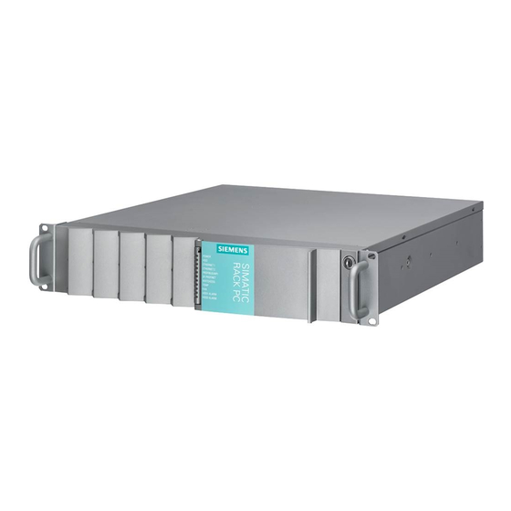
Description Overview SIMATIC IPC647C is an industrial PC in 19" rack format (2 HU) with high-performance industrial functionality. ● Highly compact ● Extremely rugged ● Extensive product continuity Figure 3-1 SIMATIC IPC647C Areas of application The SIMATIC IPC647C provides mechanical engineers, plant engineers, and control cabinet manufacturers with a high-performance, extremely flexible 19"... -
Page 14: Highlights
● SIMATIC IPC DiagMonitor Software – PC diagnostics / messaging software via OPC/SNMP/LAN ● SIMATIC PC/PG Image Creator – data imaging software ● RAID1 – redundant data storage to two hard disk volumes protects against data loss ● Optional ECC memory modules SIMATIC IPC647C Operating Instructions, 12/2010, A5E02669337-02... -
Page 15: Function
2 x 3.5" (in vibration damped drive rack) 1 x optical drive (slimline) 2x PCI or 1x PCI, 1x PCIe x4 Slots for expansion cards long 1x PCIe x16 SIMATIC IPC647C Operating Instructions, 12/2010, A5E02669337-02... - Page 16 NAMUR: Max. 20 ms at 93 V. Monitoring functions Overshoot/undershoot of permissible operating Temperature temperature Messages can be evaluated by an application program. Speed monitoring Messages can be evaluated by an application program. SIMATIC IPC647C Operating Instructions, 12/2010, A5E02669337-02...
- Page 17 Up to 8 GB, Dual Channel (without or with ECC) PROFIBUS/MPI 12 Mbps (isolated potential, compatible to CP 5611) PROFINET 10/100 Mbps (CP 1616 onboard, three RJ-45) Drives CF drive Slot for Compact Flash card, on front SIMATIC IPC647C Operating Instructions, 12/2010, A5E02669337-02...
- Page 18 MUI *, 32 bits Windows 7 MUI**, 32 bits *MUI: Multi language User Interface; 5 languages (German, English, French, Spanish, Italian) Memory expansions ≥4 GB can only be used in combination with 64-bit operating systems. SIMATIC IPC647C Operating Instructions, 12/2010, A5E02669337-02...
- Page 19 Fan speed Hard disk monitoring (SMART, RAID status) System / Ethernet monitoring (Heartbeat) SIMATIC IPC Software tool for local data backup and management of Image and Partition Creator software hard disks SIMATIC IPC647C Operating Instructions, 12/2010, A5E02669337-02...
-
Page 20: Installation
Rear view of the device (example) ① DP connection of graphics card ② Connection elements ③ Expansion slots ④ Equipotential bonding connection ⑤ Power supply connector ⑥ Fan / power supply unit SIMATIC IPC647C Operating Instructions, 12/2010, A5E02669337-02... -
Page 21: Operator Controls
Data may be lost when the PC performs a hardware reset. WARNING The on/off button signal does not cut off power to the PC! To disconnect the device completely from the power supply, pull out the power connector. SIMATIC IPC647C Operating Instructions, 12/2010, A5E02669337-02... -
Page 22: Connecting Elements
Description 3.6 Installation 3.6.3 Connecting elements Layout of the interfaces on the rear of the device SIMATIC IPC647C Operating Instructions, 12/2010, A5E02669337-02... - Page 23 Display port connection of the DP adapter at Dual Head graphics card (optional) ⑮ Connecting potentials Connection for equipotential bonding LAN interfaces are numbered on the enclosure to provide unique identification. The numbering by the operating system may deviate from this. SIMATIC IPC647C Operating Instructions, 12/2010, A5E02669337-02...
-
Page 24: Status Displays
PC status display isolated from mains YELLOW Standby (hibernating) GREEN PC in operation Display for hard disk no access access GREEN Access ETHERNET 1 * ETHERNET status No connection display No data traffic SIMATIC IPC647C Operating Instructions, 12/2010, A5E02669337-02... - Page 25 Error in early BIOS Post All lit CPU startup failure Error in early POST LAN interfaces are numbered on the enclosure to provide unique identification. The numbering by the operating system may deviate from this. SIMATIC IPC647C Operating Instructions, 12/2010, A5E02669337-02...
- Page 26 The two "virtual" CP 1616 LEDs are only visible in the SIMATIC software and can be read via SNMP. PROFINET Virtual LEDs CP is active STOP CP is in the stop state Flashes The states "flashes slowly" or "flashes rapidly" do not exist. SIMATIC IPC647C Operating Instructions, 12/2010, A5E02669337-02...
-
Page 27: Application Planning
● Verify that the shipment contains the complete unit and your separately ordered accessories. Please inform your local dealer of any disagreements or transport damage. ● Please inform Siemens AG by means of the enclosed SIMATIC IPC/PG quality control report form. - Page 28 COA label. Figure 4-2 COA label Serial number S VP ... Order no. 6AG4112-1 ... Microsoft Windows Product Key Ethernet 1 address Ethernet 2 address CP 1616 onboard layer 2 SIMATIC IPC647C Operating Instructions, 12/2010, A5E02669337-02...
-
Page 29: Ambient And Environmental Conditions
● The connected or built-in peripherals should not introduce a counter emf in excess of 0.5 V into the device. Access protection The access protection of the rack PC is only enabled if the front door is locked. SIMATIC IPC647C Operating Instructions, 12/2010, A5E02669337-02... - Page 30 Application planning 4.4 Access protection SIMATIC IPC647C Operating Instructions, 12/2010, A5E02669337-02...
-
Page 31: Installing
For more detailed information on telescopic rails, refer to the sections T echnical data of the telescopic rails (Page 1 42) and D imensional drawing for the use of telescopic rails (Page 1 45). ① Figure 5-1 Position of the mounting holes SIMATIC IPC647C Operating Instructions, 12/2010, A5E02669337-02... - Page 32 The mounting screws of the telescopic rails may not protrude more than 5 mm into the enclosure. CAUTION Risk of injury! It is not permitted to install the device only on the 19-inch brackets of the front panel. SIMATIC IPC647C Operating Instructions, 12/2010, A5E02669337-02...
-
Page 33: Connecting
The computer in question must be turned off and the power supply connector should be plugged in. During the measurement, all cables from the plant to the computer should be connected. All other components in the plant must be active. SIMATIC IPC647C Operating Instructions, 12/2010, A5E02669337-02... -
Page 34: Connecting The Device To Power
SIMATIC PCs with a PFC circuit. UPS characteristics are described and classified in the standards EN 50091-3 and IEC 62040-3. Devices with sinusoidal output voltage in the normal and buffered mode are identified with the classification "VFI-SS-.." or "VI-SS-..". SIMATIC IPC647C Operating Instructions, 12/2010, A5E02669337-02... - Page 35 4.5 m, and tandem grounded connector 15 A, min. 250 V. Label on the device The back of the device has a warning label in English, Norwegian, Finnish and Chinese informing the user that the device must be connected to properly grounded electrical outlets. SIMATIC IPC647C Operating Instructions, 12/2010, A5E02669337-02...
- Page 36 (1). WARNING If the power plug is secured with a clamp, the power outlet must be freely accessible to allow the device to be easily removed from the mains. SIMATIC IPC647C Operating Instructions, 12/2010, A5E02669337-02...
-
Page 37: Equipotential Bonding
To fix the strain relief, you will need a TORX T10 screwdriver. To fix the PROFINET strain relief, you will need a TORX T10 screwdriver. Steps for connecting the strain relief 1. Remove the PROFINET interface plate. SIMATIC IPC647C Operating Instructions, 12/2010, A5E02669337-02... - Page 38 2. Install the plate for the Profinet and Ethernet connectors. Use the retaining screw of the PROFINET interface plate for this purpose. 3. Install the Profinet and Ethernet connectors at the respective positions and fasten the cables with cable ties. SIMATIC IPC647C Operating Instructions, 12/2010, A5E02669337-02...
-
Page 39: Commissioning
● Before you switch on the device, you should verify that all peripheral devices such the keyboard, mouse, monitor and the power supply are connected. ● The operating system of your device is preinstalled on the hard disk. SIMATIC IPC647C Operating Instructions, 12/2010, A5E02669337-02... -
Page 40: Initial Commissioning - Initial Startup
Press the on/off button behind the front panel door. The green power LED is switched off. WARNING Completely separating the device from the power supply For complete separation of the device from the power supply pull the power connector. SIMATIC IPC647C Operating Instructions, 12/2010, A5E02669337-02... -
Page 41: Windows Xp, Windows 7 Security Center
7.4.1 Compact Flash card rack (optional) NOTICE We highly recommend that use use approved SIMATIC Compact Flash cards. Siemens disclaims any liability for impairment of functions caused by the use of third-party cards. Installation It is possible to operate the optional CompactFlash card rack with a CompactFlash card as a flash drive. - Page 42 5 seconds. The cluster size is 4 KB in this case. Due to the file segmentation, the file is always written to another location on the Compact Flash card. With this example, the Compact Flash card has a theoretical service of 79.3 years. SIMATIC IPC647C Operating Instructions, 12/2010, A5E02669337-02...
- Page 43 The procedure for installing an operating system is described in the section I nstalling Windows (Page 1 11). How to change the boot priority in the BIOS setup is described in the section B oot Menu (Page 1 95). SIMATIC IPC647C Operating Instructions, 12/2010, A5E02669337-02...
-
Page 44: Dvd Burner
7.4.3 Removable hard disks The removable racks support hot plugging in a RAID1 system. If, however, you have configured a non-RAID system, you will need to turn the device off before exchanging the rack. SIMATIC IPC647C Operating Instructions, 12/2010, A5E02669337-02... - Page 45 ② HDD activity display You should also check the HDD access ⑦ ⑥ display , HDD 1 ALARM or HDD 2 ⑤ ALARM See also the section S tatus displays (Page 2 4) . SIMATIC IPC647C Operating Instructions, 12/2010, A5E02669337-02...
-
Page 46: 2Hdd System (Optional)
NOTICE The drive letters for the partitions on both drives are assigned by the operating system used. You can change these in the Control Panel as required. SIMATIC IPC647C Operating Instructions, 12/2010, A5E02669337-02... -
Page 47: Raid System
Note You can find information regarding Intel RAID controllers in the RAID documentation on the included "Documentation and Drivers" CD in the Drivers\RAID\Intel directory. Figure 7-1 Example SIMATIC IPC647C Operating Instructions, 12/2010, A5E02669337-02... - Page 48 (hours, in case of a high hard disk load even days) to synchronize a new hard disk in the background, depending on its size and on the system load. The safe RAID Level 1 system state is achieved again only after synchronization is completed. SIMATIC IPC647C Operating Instructions, 12/2010, A5E02669337-02...
- Page 49 The functioning drive can be located using the following pictures and tables. The table and information below apply only to the delivery state of the device, that is if no changes or expansions were made. SIMATIC IPC647C Operating Instructions, 12/2010, A5E02669337-02...
- Page 50 Port 2 Device Port 2 SATA2 Drive rack ② Drive ⑤ If the hard disk is defective and SIMATIC monitoring software is installed, the LEDs ⑥ light up individually or simultaneously on the front. SIMATIC IPC647C Operating Instructions, 12/2010, A5E02669337-02...
- Page 51 To be able to boot from the RAID system, you must place this first in the list of bootable sources in the BIOS "Boot" setup menu. Otherwise the system will boot from the hard disk you have just installed and the message "Operating system not found" will be displayed. SIMATIC IPC647C Operating Instructions, 12/2010, A5E02669337-02...
- Page 52 You can also choose to reboot the device. In this case, the RAID software automatically integrates the new HDD. The "Rebuild to another Disk" command synchronizes the RAID volumes. Figure 7-6 Example SIMATIC IPC647C Operating Instructions, 12/2010, A5E02669337-02...
- Page 53 The new hard disk is then assigned to a SATA port and can be included in the RAID array. The "Rebuild to another Disk" command initiates synchronization of the RAID1 system. Figure 7-7 Example SIMATIC IPC647C Operating Instructions, 12/2010, A5E02669337-02...
- Page 54 Commissioning 7.4 Notes on operation ① A defective drive continues to be displayed during the rebuilding process. This drive disappears from the display when the rebuild process has been completed. Figure 7-8 Example SIMATIC IPC647C Operating Instructions, 12/2010, A5E02669337-02...
-
Page 55: Integration Into An Automation System
You can create, run or configure PROFINET IO applications with the Development Kit DK- 16xx PN IO. It must be installed in addition to the CP 16xx.sys device driver. You can obtain information about this from your Siemens sales partner. SIMATIC IPC647C... -
Page 56: Profinet
You will find this information on the SIMATIC NET Manual Collection CD. The software package and the documentation are not parts of the development package. Additional information You can find additional information in the catalog and the Siemens online ordering system: Industrial Automation and Drive Technologies ( ttp://mall.automation.siemens.com). - Page 57 Read this guide if you want to install the NDIS device Device Driver CP16xx.sys driver, CP16xx.sys. Further information You can find the information on specific products in the Internet at the address: Product- related Information SIMATIC NET ( ttp://www.siemens.com/simatic-net) SIMATIC IPC647C Operating Instructions, 12/2010, A5E02669337-02...
- Page 58 Integration into an automation system 8.2 PROFINET SIMATIC IPC647C Operating Instructions, 12/2010, A5E02669337-02...
-
Page 59: Functions
AMT is a technology from Intel for remote maintenance of computers. You turn an AMT PC on and off remotely and start the BIOS setup remotely. Different operating systems can be booted with ISO files. SIMATIC IPC647C Operating Instructions, 12/2010, A5E02669337-02... -
Page 60: Temperature Monitoring/Display
The temperature error is retained in memory until temperatures have fallen below the thresholds and are reset by one of the following measures: ● Acknowledgment of the error message by the monitoring software ● Restart of the device SIMATIC IPC647C Operating Instructions, 12/2010, A5E02669337-02... -
Page 61: Watchdog (Wd)
The monitoring times can be set in increments of one second within a range from 3 to 255 seconds. Note The watchdog is retriggered if the monitoring time is changed at the active watchdog (that is while the watchdog is running)! SIMATIC IPC647C Operating Instructions, 12/2010, A5E02669337-02... -
Page 62: Fan Monitoring
The information can be read from an I/O register and evaluated. When the first warning level is reached, the remaining service life of the battery for buffering CMOS data amounts to at least 1 month. SIMATIC IPC647C Operating Instructions, 12/2010, A5E02669337-02... -
Page 63: Amt (Active Management Technology)
You configure AMT using the BIOS setup and the MEBx (Management Engine BIOS Extension). MEBx is a BIOS extension for configuring AMT. 4. When the BIOS appears briefly during startup, press the <Ctrl+P> keyboard shortcut. The "MEBx" dialog opens. SIMATIC IPC647C Operating Instructions, 12/2010, A5E02669337-02... - Page 64 Functions 9.7 AMT (Active Management Technology) SIMATIC IPC647C Operating Instructions, 12/2010, A5E02669337-02...
-
Page 65: Expansions And Parameter Assignment
(for the interface interlock on the rear panel.) Preparation Disconnect the device from the mains. WARNING Unauthorized opening of device without previously disconnecting power may result in substantial damage to equipment and/or danger to the user. SIMATIC IPC647C Operating Instructions, 12/2010, A5E02669337-02... - Page 66 How to open the device 1. Open the front door to about 45° to release the lock of the front panel. 2. Remove the front panel. ① 3. Remove the cover screws (Torx T10). SIMATIC IPC647C Operating Instructions, 12/2010, A5E02669337-02...
- Page 67 Expansions and parameter assignment 10.1 Open the device. How to open the device 4. Hit the screwdriver lightly with the ball of your hand to release the cover. 5. Push the cover back and remove it. SIMATIC IPC647C Operating Instructions, 12/2010, A5E02669337-02...
-
Page 68: Memory Expansion
The electronic components on the PCBs are highly sensitive to electrostatic discharge. Always take appropriate precautionary measures when handling these components. Refer to the ESD directives on handling of electrostatically sensitive components: E SD Guidelines (Page 2 21) . SIMATIC IPC647C Operating Instructions, 12/2010, A5E02669337-02... - Page 69 1. Open the device. – O pen the device. (Page 6 5). 2. Open the two latches (1) at the sides of the memory module. Remove the memory module (2) from the slot. 3. Close the device. SIMATIC IPC647C Operating Instructions, 12/2010, A5E02669337-02...
- Page 70 5. Close the device. Display of the current memory configuration The new memory configuration is detected automatically. The allocation of the ”base memory and extended memory” is automatically displayed when you switch on the device. SIMATIC IPC647C Operating Instructions, 12/2010, A5E02669337-02...
-
Page 71: Installation And Removal Of Expansion Modules
PROFINET module (such as a CP 1616) can be installed in the system. 10.3.2 Installation and removal of the bus frame Preparation Disconnect the device from the mains and unplug all cables. Open the device as described in section O pen the device. (Page 6 5). SIMATIC IPC647C Operating Instructions, 12/2010, A5E02669337-02... - Page 72 Do not ② touch the gold contacts of the bus module as this may lead to contact problems when operating the device. Avoid contamination or damage to the gold contact pins for the edge-socket connector. SIMATIC IPC647C Operating Instructions, 12/2010, A5E02669337-02...
-
Page 73: Installation And Removal Of Expansion Modules In The Bus Frame
● PCIe x16 (for I/O expansion modules or graphics cards) Preparation You have removed the bus frame. For details of how to do this, see section I nstallation and removal of the bus frame (Page 7 1) SIMATIC IPC647C Operating Instructions, 12/2010, A5E02669337-02... - Page 74 The second bracket is attached to the bus frame by another screw. Open the side of the bus frame by swinging it out. SIMATIC IPC647C Operating Instructions, 12/2010, A5E02669337-02...
- Page 75 Make sure that the module is seated correctly in the edge-socket connector. Do not tilt the module. Screw down the bracket of the expansion and the other removed bracket if needed. SIMATIC IPC647C Operating Instructions, 12/2010, A5E02669337-02...
- Page 76 Information about original spare parts for SIMATIC PCs is available on the Internet at: After-sales information system for SIMATIC PC / PG (http://www.siemens.de/asis). Latching retainers for the IPC647C are available under the following order number: A5E02719654. SIMATIC IPC647C Operating Instructions, 12/2010, A5E02669337-02...
- Page 77 The expansion module is installed in the bus frame. Not insert the bus frame back into the device, as described in the section I nstallation and removal of the bus frame (Page 7 1). SIMATIC IPC647C Operating Instructions, 12/2010, A5E02669337-02...
-
Page 78: Drive Racks And Storage Media
You can mount the following drives and media In the drive racks: ● Hard disk drive (HDD) ● Solid-State Drive (SSD) ● Card rack for Compact Flash Card (CF memory card) ● DVD drive SIMATIC IPC647C Operating Instructions, 12/2010, A5E02669337-02... - Page 79 Removable rack with carriers for storage media Vibration damped drive rack ① Vibration damped drive rack ② Two slots for storage media (shock and vibration damped) ③ Slimline mounting bay for DVD drive for CF card rack SIMATIC IPC647C Operating Instructions, 12/2010, A5E02669337-02...
-
Page 80: Installation And Removal Of Drive Racks
Torx T10 screwdriver. Loosen the identified screws behind the front panel with a Torx T10 screwdriver. Pull the power plugs for the Slimline drive rack and any mounted SSD drives on the motherboard. SIMATIC IPC647C Operating Instructions, 12/2010, A5E02669337-02... - Page 81 Remove the drive rack out of the device. The drive rack is removed from the device. Installing the driver carrier Perform the tasks describe above in reverse order. SIMATIC IPC647C Operating Instructions, 12/2010, A5E02669337-02...
-
Page 82: Removing And Inserting The Hdd Carrier
Press on the release next to the locking switch in the direction of the arrow to lower the lever on the HDD carrier. Pull the lever out until you feel the HDD carrier release and pull it out completely. SIMATIC IPC647C Operating Instructions, 12/2010, A5E02669337-02... -
Page 83: Installation And Removal Of Hdds
● Vibration damped drive rack: Direct mounting in the drive rack Requirement for the removing or installing the HDD Remove the drive rack from the device as described in the section I nstallation and removal of drive racks (Page 8 0). SIMATIC IPC647C Operating Instructions, 12/2010, A5E02669337-02... - Page 84 Always use only the specified original screws for the installation. Insert the HDD carrier again as described in section R emoving and inserting the HDD carrier (Page 8 2). SIMATIC IPC647C Operating Instructions, 12/2010, A5E02669337-02...
-
Page 85: Installation And Removal Of Cf Card Rack
9. If necessary, remove the CF card from the CF card rack. 10. Remove the drive rack from the device as described in the section I nstallation and removal of drive racks (Page 8 0). SIMATIC IPC647C Operating Instructions, 12/2010, A5E02669337-02... - Page 86 Do not pull on the cable. Loosen the four screws on the CF card rack and remove the CF card rack from the mounting plate. SIMATIC IPC647C Operating Instructions, 12/2010, A5E02669337-02...
-
Page 87: Installation And Removal Of Dvd Drive
● Vibration damped drive rack ● Drive rack for a removable rack Preparations 11. Remove the drive rack from the device as described in the section . 12. Disconnect the connecting cable from the DVD drive. SIMATIC IPC647C Operating Instructions, 12/2010, A5E02669337-02... -
Page 88: Installation And Removal Of Ssds
Requirement for the removing or installing the SSD Remove the drive rack with the removable rack from the device as described in the section I nstallation and removal of drive racks (Page 8 0). SIMATIC IPC647C Operating Instructions, 12/2010, A5E02669337-02... - Page 89 HDD carrier with a Torx T10 screwdriver. The SSD is removed from the HDD carrier. Installing an SSD in the HDD carrier Perform the tasks describe above in reverse order. SIMATIC IPC647C Operating Instructions, 12/2010, A5E02669337-02...
- Page 90 SSD to the mounting plate. Remove the SSD from the mounting plate. Pull out the plug from the SSD. Installing an SSD with mounting plate Perform the tasks describe above in reverse order. SIMATIC IPC647C Operating Instructions, 12/2010, A5E02669337-02...
-
Page 91: Service And Maintenance
Disclaimer of liability All technical data and approvals apply only to expansion units which are released by SIEMENS. No liability can be accepted for impairment of functions caused by the use of third-party devices or components. SIMATIC IPC647C Operating Instructions, 12/2010, A5E02669337-02... -
Page 92: Preventive Maintenance
You may only use filters of the same type. Information about original spare parts for SIMATIC PCs is available on the Internet at: After-sales information system for SIMATIC PC/PG ( ttp://www.siemens.com/asis) Filter meshes are available under the following order number: A5E02318854. SIMATIC IPC647C Operating Instructions, 12/2010, A5E02669337-02... - Page 93 Make absolutely certain that you do not fit the outer side of the filter on the inside. Generally, the outer side is much more dirty than inner side if it has been in use for some time. SIMATIC IPC647C Operating Instructions, 12/2010, A5E02669337-02...
-
Page 94: Replacing Device Fans
Remove the front panel and, if necessary, replace the filter. See section R eplacing filters (Page 9 2) Release the knurled screws of the fan holder. Take the fan holder out of the housing. SIMATIC IPC647C Operating Instructions, 12/2010, A5E02669337-02... - Page 95 Note: The connectors are locked. To unlock them, press down the tongue on the connector of the fan cable. Remove the two screws (Torx ① 20) for each fan and remove the fan from the fan holder. SIMATIC IPC647C Operating Instructions, 12/2010, A5E02669337-02...
- Page 96 How to install the device fan Fasten the new fans with two screws (Torx 20) per fan to the fan holder. Note the direction of the arrow on the fan. The picture shows the proper fan mounting position. SIMATIC IPC647C Operating Instructions, 12/2010, A5E02669337-02...
- Page 97 Place the fan holder in the housing. Note the positioning guides on the base of the front frame. The fan holder must lie level on the front frame. Secure the fan holder with the knurled screw. SIMATIC IPC647C Operating Instructions, 12/2010, A5E02669337-02...
-
Page 98: Replacing The Backup Battery
A table in which you can log your settings is available in the section B IOS Setup default settings (Page 2 01). 13. Disconnect the device from the power supply and remove all connecting cables from the device. SIMATIC IPC647C Operating Instructions, 12/2010, A5E02669337-02... - Page 99 3. Applying a slight pressure, press the new battery into the socket. Make sure you do not use metal objects for this. Make sure not to short-circuit the battery during handling. 4. Close the device. SIMATIC IPC647C Operating Instructions, 12/2010, A5E02669337-02...
-
Page 100: Removing The Power Supply Module
Remove the bus frame, see I nstallation and removal of the bus frame (Page 7 1). Disconnect all the cables coming out of the power supply unit. Remove the cable ties securing the power cables in the housing. SIMATIC IPC647C Operating Instructions, 12/2010, A5E02669337-02... - Page 101 11.1 Removing and installing hardware components How to remove the power supply unit Remove the identified retaining screws. Pull the power supply unit towards the front (1) and lift it out of the device (2). SIMATIC IPC647C Operating Instructions, 12/2010, A5E02669337-02...
-
Page 102: Installation And Removal Of Bus Boards In The Bus Frame
Insert the desired main bus board into the middle rack of the bus frame and align the mounting holes to the holes there. SIMATIC IPC647C Operating Instructions, 12/2010, A5E02669337-02... - Page 103 Perform the tasks describe above in reverse order. Use a screwdriver to press on the end of the expansion rivet until the expansion rivet can be freely moved. Use only new expansion rivets to re-install a bus board. SIMATIC IPC647C Operating Instructions, 12/2010, A5E02669337-02...
-
Page 104: Removing The Op
(Page 7 1). 2. Remove the CPU cooler as described – in the section R eplacing the CPU ③ cooler (Page 1 07) ① 3. Loosen the screws on the ② traverse SIMATIC IPC647C Operating Instructions, 12/2010, A5E02669337-02... -
Page 105: Removing The Motherboard
SIMATIC PC/PG ( ttp://www.siemens.com/asis) 18. Disconnect the device from the power supply and remove all connecting cables from the device. 19. Open the device as described in section O pen the device. (Page 6 5). SIMATIC IPC647C Operating Instructions, 12/2010, A5E02669337-02... - Page 106 Use 4.5-mm hex key to remove the indicated hex bolts. The motherboard is supplied as spare part with processor (soldered to the motherboard), but without a CPU cooler, memory modules and bus board. SIMATIC IPC647C Operating Instructions, 12/2010, A5E02669337-02...
-
Page 107: Replacing The Cpu Cooler
11.1 Removing and installing hardware components 11.1.10 Replacing the CPU cooler The CPU cooler installed in the SIMATIC IPC647C uses heat pipes and an additional heat exchanger. CAUTION The CPU cooler may only be removed by authorized technical personnel. Information about... - Page 108 5. Verify that there is no residue on the processor chip from the CPU cooler's heat sink pad. If there is, clean the processor surface and replace the CPU cooler. SIMATIC IPC647C Operating Instructions, 12/2010, A5E02669337-02...
-
Page 109: Processor Replacement
1 05). 11.2 Reinstalling the software 11.2.1 General installation procedure If your software is corrupt, you can reinstall it using the recovery CD or DVD, the Documentation and Drivers CD and the Restore DVD. SIMATIC IPC647C Operating Instructions, 12/2010, A5E02669337-02... -
Page 110: Restoring The Factory State Of The Software Using The Restore Dvd
All data on drive C: of the hard disk will be deleted. Setup formats the hard disk and installs the original factory software. If "Restore entire hard disk" is set ALL data, user settings, authorizations or license keys will be lost on the hard disk. SIMATIC IPC647C Operating Instructions, 12/2010, A5E02669337-02... -
Page 111: Installing Windows
F12 key. The boot menu displayed after initialization indicates all boot devices. 22. Select the CD/DVD drive. Follow the instructions on the screen until the "Siemens SIMATIC Recovery" window is displayed. When using the recovery function with Windows 7, confirm that you want to boot from CD or DVD immediately at startup. -
Page 112: Setting Up Partitions For Windows Xp And Server 2008 Operating Systems
To display the proposed list completely, you may need to scroll down with the arrow keys. – Selection at AHCI: "Intel(R) 5 Series 6 Port SATA AHCI Controller" – Selection with RAID: "Intel(R) ICH8M-E/ICH9M-E/5 Series SATA RAID Controller" SIMATIC IPC647C Operating Instructions, 12/2010, A5E02669337-02... -
Page 113: Setting Up The Language Selection By Means Of The Multilanguage User Interface (Mui)
Now follow the on-screen instructions. It may take several minutes before the next prompt for the product key is displayed. Note Due to the previous activation, you do not need to enter the product key (COA number). This is entered automatically during the installation. SIMATIC IPC647C Operating Instructions, 12/2010, A5E02669337-02... - Page 114 Options Meaning Drive options (advanced) Further functions are displayed with which you can set up the hard disk. Load Driver To add new drivers, for example the driver for RAID. SIMATIC IPC647C Operating Instructions, 12/2010, A5E02669337-02...
- Page 115 25 GB NTFS not compressed Second Windows 7, Server 2008 DATA Remainder NTFS not compressed Following a required reboot, Windows will be installed on the hard disk. This process takes at least 20 minutes. SIMATIC IPC647C Operating Instructions, 12/2010, A5E02669337-02...
- Page 116 You will find the necessary files on the recovery DVD in the "Languagepacks" folder. Start > Control Panel > Clock, Language, and Region > Change display language > Regional and Language options > Keyboards and Languages Additional languages can be integrated through Windows Update. SIMATIC IPC647C Operating Instructions, 12/2010, A5E02669337-02...
-
Page 117: Installing Drivers And Software
To display the proposed list completely, you may need to scroll down with the arrow keys. – Selection at AHCI: "Intel(R) 5 Series 6 Port SATA AHCI Controller" – Selection with RAID: "Intel(R) ICH8M-E/ICH9M-E/5 Series SATA RAID Controller" SIMATIC IPC647C Operating Instructions, 12/2010, A5E02669337-02... -
Page 118: Installing The Burner Software
Contact the manufacturer to obtain updates of drivers and application programs you purchased from third-party vendors. NOTICE Before you install new drivers or operating system updates for Windows MUI versions, set the default language to US English in the regional settings for menus and dialogs. SIMATIC IPC647C Operating Instructions, 12/2010, A5E02669337-02... -
Page 119: Data Backup / Subsequent Modification Of Partitions
Compact Flash cards, HDDs and individual partitions (images.) The "SIMATIC IPC Image & Partition Creator" only supports burning to DVD media. The software can be ordered from the Siemens online ordering system. For detailed information about "SIMATIC IPC Image & Partition Creator", please refer to the corresponding product documentation. -
Page 120: Bios Update
Several reboots can be carried out after a BIOS update. These reboots are initiated by the Management Engine (ME). The reboots are required by the ME to adapt itself to the changes in the BIOS update. SIMATIC IPC647C Operating Instructions, 12/2010, A5E02669337-02... -
Page 121: Bios Recovery
39. Close the housing cover. 40. Place the Siemens BIOS Update USB stick into an USB slot of the device front. 41. Connect the device to the power supply. Recovery is executed automatically and cannot be interrupted or operated. The recovery progress will be displayed on the screen. -
Page 123: Alarm, Error, And System Messages
Set up cache as RAM Service case SEC_ACCESS_CSR PCIE MMIO Initialize PCIE Service case Base Address initial SEC_GENERIC_MSRINIT CPU Generic Initialize CPU MS Service case MSR initial (Machine Status) Register SEC_CPU_SPEEDCFG Setup CPU Specify CPU speed Service case speed SIMATIC IPC647C Operating Instructions, 12/2010, A5E02669337-02... - Page 124 Setup SMM Setup SMM access Service case ACCESS service service DXE_NB_INIT North bridge Initialization of the Service case Middle initial North Bridge DXE_SIO_INIT Super I/O DXE Initialization of the Service case initial Super IO SIMATIC IPC647C Operating Instructions, 12/2010, A5E02669337-02...
- Page 125 Send END of Terminate Boot Service case POST Message Service to ME via HECI BDS_LEGACY_BOOT_EVENT Last Chipset Initialization of the last Service case initial before chipset before the boot to Legacy Legacy OS Boot SIMATIC IPC647C Operating Instructions, 12/2010, A5E02669337-02...
- Page 126 BDS_CONNECT_STD_ERR Error report Initialize default error Service case device initial output BDS_CONNECT_USB_HC USB host Initialize USB host Service case controller initial controller BDS_CONNECT_USB_BUS USB BUS driver Initialize USB bus Service case initial driver SIMATIC IPC647C Operating Instructions, 12/2010, A5E02669337-02...
- Page 127 Setup SB SouthBridge IOTRAP Service case IOTRAP Service service DXE_SUBCLASS_DRIVER Build AMT Table Initialization of the Service case AMT (Active Management Technology) table DXE_PPM_INIT PPM Initial Initialization of the Service case Processor Power Management SIMATIC IPC647C Operating Instructions, 12/2010, A5E02669337-02...
- Page 128 BIOS Recovery Check whether the not found image not found BIOS Recovery image exists on the recovery medium (e.g. USB stick). PEI_RECOVERY_LOAD_FILE_DONE Load Recovery Loading of BIOS Service case Image complete Recovery image completed SIMATIC IPC647C Operating Instructions, 12/2010, A5E02669337-02...
-
Page 129: Boot Error Messages
Set the RESET CONFIGURATION DATA option in the "Advanced" menu of Setup. Contact your Technical Support. Allocation Error for ... Plug and Play problem Undo the last hardware change. Contact your Technical Support. SIMATIC IPC647C Operating Instructions, 12/2010, A5E02669337-02... - Page 130 Contact Technical Support. Screen remains dark - cursor A data carrier is inserted in the ODD drive. In this case it can take flashes at top left several minutes until the BIOS power up is continued. SIMATIC IPC647C Operating Instructions, 12/2010, A5E02669337-02...
-
Page 131: Troubleshooting/Faqs
BIOS Setup. the PC. 2. Adjust the time and date in BIOS Setup. Although the BIOS setting is The backup battery is low. Contact Technical Support. OK, the time and data are still incorrect. SIMATIC IPC647C Operating Instructions, 12/2010, A5E02669337-02... - Page 132 KVM switch does not pass information through DDC information. Use a basic cable adapter with DVI-I to VGA Y cable adapter with DVI-I for connector. DVI-D/VGA connector is being used SIMATIC IPC647C Operating Instructions, 12/2010, A5E02669337-02...
- Page 133 See section CP 1616 onboard communications 1616 onboard interface processor (Page 207). All front-panel LEDs are Error in early BIOS-POST In this case, contact Technical Support. constantly lit Also see section Overview of the monitoring functions (Page 59). SIMATIC IPC647C Operating Instructions, 12/2010, A5E02669337-02...
-
Page 134: Problems When Using Modules Of Third-Party Manufacturers
If the error no longer occurs, the Connector pin assignments third-party module was the cause of the fault. Replace the deviate thrid-party module with a Siemens module or contact the No "Reset Configuration" in module supplier. BIOS SETUP Force a "Reset Configuration"... -
Page 135: Technical Specifications
± 2 kV (to IEC 61000-4-4; Burst; Length > 30 m) ± 2 kV (to IEC 61000-4-5; Length > 30 m) Immunity to discharge of static ± 6 kV contact discharge (to IEC 61000-4-2) electricity ± 8 kV air discharge (according to IEC 61000-4-2) SIMATIC IPC647C Operating Instructions, 12/2010, A5E02669337-02... - Page 136 1066 MT/sec FSB, 3 MB cache, EM64T, VT, 2 cores / 4 threads), AMT Intel® Core™ i7-610E, 2.53 GHz Turbo Boost, 1066MT/sec FSB, 4 MB cache, EM64T, VT, 2 cores / 4 threads), AMT SIMATIC IPC647C Operating Instructions, 12/2010, A5E02669337-02...
- Page 137 Slot for Compact Flash card (behind the door, accessible from the front) Slot type II Chipset Main memory interface Max. 8 GB SDRAM DDR3 (PC3-8500), unbuffered, ECC, no Module types: 1 Gbit or 2 Gbit technology x8 and x16 organized SIMATIC IPC647C Operating Instructions, 12/2010, A5E02669337-02...
- Page 138 9-pin D–sub socket, CP5611-compatible, 9.6 Kbps to 12 Mbps, programmable with software Electrically isolated RS485 (SELV circuit)* PROFINET 3x RJ45 interface, CP 1616 compatible onboard interface based on ERTEC 400, 10/100 Mbps electrically isolated * SIMATIC IPC647C Operating Instructions, 12/2010, A5E02669337-02...
- Page 139 LAN interfaces are numbered on the enclosure to provide unique identification. The numbering by the operating system may deviate from this. AMT and teaming cannot be used simultaneously on the Ethernet interface. Interfaces supplied as optional. SIMATIC IPC647C Operating Instructions, 12/2010, A5E02669337-02...
-
Page 140: Power Requirements Of Components (Maximum Values)
Power consumption (AC-SV, U=230 V) Base device 0.2 A 45 W Hard disk drive 1 x 3.5" 0.04 A Hard disk drives 2 x 3.5" 0.08 A 18 W DVD burner drive 0.02 A SIMATIC IPC647C Operating Instructions, 12/2010, A5E02669337-02... -
Page 141: Power Supply (Ac)
The accumulated power of the +5 V and + 3.3 V supply may not exceed 190 W Maximum inrush current at: 110 VAC = 25 A / 5 ms 230 VAC = 30 A / 5 ms Power Good Signal Figure 14-1 Timing profile of the Power Good Signal SIMATIC IPC647C Operating Instructions, 12/2010, A5E02669337-02... -
Page 142: Technical Data Of The Telescopic Rails
"VFI-SS-.." or "VI-SS-..". 14.4 Technical data of the telescopic rails Ultimate load per pair At least 14 kg Full extraction length At least 470 mm Rail thickness Maximum 9.7 mm Mounting screws M5 x 6 mm SIMATIC IPC647C Operating Instructions, 12/2010, A5E02669337-02... -
Page 143: Dimension Drawings
Dimension drawings 15.1 Dimensional drawing of the device SIMATIC IPC647C Operating Instructions, 12/2010, A5E02669337-02... - Page 144 Dimension drawings 15.1 Dimensional drawing of the device 481,4 Alle Angaben in mm. Figure 15-1 Dimensions IPC647C SIMATIC IPC647C Operating Instructions, 12/2010, A5E02669337-02...
-
Page 145: Dimensional Drawings For Installation Of Expansion Modules
● Type RP 3659.180 for 600 mm cabinet ● Type RP 3659.190 for 800 mm cabinet 34,83 1.37 3.97 3.97 3.97 Units of measurement: Inch Figure 15-3 Dimensional drawing for the use of telescopic rails SIMATIC IPC647C Operating Instructions, 12/2010, A5E02669337-02... -
Page 147: Detailed Descriptions
Flash BIOS and the backup battery. Figure 16-1 Layout of the motherboard ① ③ Two memory module slots Slot for the bus board ② ④ Processor without fan Backup battery SIMATIC IPC647C Operating Instructions, 12/2010, A5E02669337-02... -
Page 148: Technical Features Of The Motherboard
Component / interface Description Parameters Mobile Intel® 5 chipset QM57 Express Chipset Single chipset (Platform Controller Hub) Insyde modified by Siemens BIOS Update by means of software VT and multimedia support Intel® Core™ i Turbo Boost and AMT, depending on CPU ... - Page 149 Optional product feature Depends on the CPU type Depending on the selected device configuration, a floppy disk drive cannot be ordered using the configurator. AMT and teaming cannot be used simultaneously on the Ethernet interface. SIMATIC IPC647C Operating Instructions, 12/2010, A5E02669337-02...
-
Page 150: Position Of The Interfaces On The Motherboard
● Interfaces for the connection of external devices ● Interfaces for internal components (drives, bus boards etc.) X132 X302 X609 top X615 bottom X617 bottom X610 X130 X133 PROFIBUS / PROFINET (optional) X608 X131 X420 SIMATIC IPC647C Operating Instructions, 12/2010, A5E02669337-02... -
Page 151: External Interfaces
Ethernet 1 and 2 Extern X40, 41 RJ45 DVI-I Extern X302 Combined socket: 24-pin DVI-D plus 5-pin VGA Microphone Extern X60 (top) 6-pin 3.5-mm phono jack Line out Extern 6-pin 3.5-mm phono jack (bottom) SIMATIC IPC647C Operating Instructions, 12/2010, A5E02669337-02... - Page 152 Automatically new line Output (open collector) / ERROR Device error Input (4.7 kΩ pull up) / INIT Reset / Initialization Output (open collector) / SELECT IN Printer selection Output (open collector) 18 – 25 Ground – SIMATIC IPC647C Operating Instructions, 12/2010, A5E02669337-02...
- Page 153 + 5 V (fused) Output – Data Data channel Input / output + Data Data channel Input / output Ground – The connectors are of type A. The ports are rated as high-current USB 2.0 (500 mA). SIMATIC IPC647C Operating Instructions, 12/2010, A5E02669337-02...
- Page 154 Signal line A of the MPI module Input/output RTS_PG RTS output signal of the MPI module. The Output control signal is "1" when the programming device is sending. Shield on connector casing Optional product feature SIMATIC IPC647C Operating Instructions, 12/2010, A5E02669337-02...
- Page 155 Input / output Shield – LED 1 Off: 10 Mbps – Lit in green color: 100 Mbps Lit in orange color: 1000 Mbit/s LED 2 Lit: Active connection – (to a hub, for example) Flashing: actvity SIMATIC IPC647C Operating Instructions, 12/2010, A5E02669337-02...
- Page 156 + 5 V + 5 V (fused) Output Ground – – Not used – DDC_DAT Display data channel data Input/output EXT_H Horizontal synchronizing pulse Output EXT_V Vertical synchronizing pulse Output DDC_CLK Display data channel clock Input/output SIMATIC IPC647C Operating Instructions, 12/2010, A5E02669337-02...
- Page 157 TX0N TDMS data 0- Output TX0P TDMS data 0+ Output Ground – Not used – Not used – Ground – TXCP TDMS clock + Output TXCN TDMS clock - Output DVI-I port DVI-I port SIMATIC IPC647C Operating Instructions, 12/2010, A5E02669337-02...
- Page 158 MONDET Hotplug detect Input TX0N TDMS data 0- Output TX0P TDMS data 0+ Output Ground – Not used – Not used – Ground – TXCP TDMS clock + Output TXCN TDMS clock - Output SIMATIC IPC647C Operating Instructions, 12/2010, A5E02669337-02...
- Page 159 Line Out, headphone interface, X60 below Line Out interface Pin no. Short name Meaning Input / output Logic ground Output Left Left channel Output Analog ground Output Sense Switch contact for device identification Input Right Right channel Output SIMATIC IPC647C Operating Instructions, 12/2010, A5E02669337-02...
-
Page 160: Internal Ports
SCSI HD_N 0-V level means that the SCSI Input interface is active External Reset, X6, Type JST B2B-PH-SM3-TB Pin no. Short name Meaning Input / Output Ground Reset 0 V level means reset Input SIMATIC IPC647C Operating Instructions, 12/2010, A5E02669337-02... - Page 161 SATA data interface, X50, 51, 52, 53, 54, 55 Pin no. Short name Meaning Input / output Ground TX-P Transmitter positive Output TX-N Transmitter negative Output Ground RX-N Receiver negative Input RX-P Receiver positive Input Ground SIMATIC IPC647C Operating Instructions, 12/2010, A5E02669337-02...
- Page 162 Pin assignment of the PEG interface (PCIe X16 socket), X610 Signal Pin no. Pin no. Signal P12V P12V P12V P12V P12V P12V SMB_CLK2 n.c. SMB_DATA2 n.c. n.c. P3V3 n.c. n.c. P3V3 AUX_3V P3V3 WAKE2 PCIE_RESET_L n.c. PCIE0_ECLK SIMATIC IPC647C Operating Instructions, 12/2010, A5E02669337-02...
- Page 163 PCIEX16_RX_P(13) PCIEX16_RX_N(13) PCIEX16_TX_P(12) PCIEX16_TX_N(12) PCIEX16_RX_P(12) n.c. PCIEX16_RX_N(12) SDVO_CTRLDATA n.c. PCIEX16_TX_P(11) n.c. PCIEX16_TX_N(11) PCIEX16_RX_P(11) PCIEX16_RX_N(11) PCIEX16_TX_P(10) PCIEX16_TX_N(10) PCIEX16_RX_P(10) PCIEX16_RX_N(10) PCIEX16_TX_P(9) PCIEX16_TX_N(9) PCIEX16_RX_P(9) PCIEX16_RX_N(9) PCIEX16_TX_P(8) PCIEX16_TX_N(8) PCIEX16_RX_P(8) MCH_CFG_20 PCIEX16_RX_N(8) PCIEX16_TX_P(7) n.c. PCIEX16_TX_N(7) PCIEX16_RX_P(7) PCIEX16_RX_N(7) PCIEX16_TX_P(6) PCIEX16_TX_N(6) SIMATIC IPC647C Operating Instructions, 12/2010, A5E02669337-02...
- Page 164 PCIEX16_RX_P(0) n.c. PCIEX16_RX_N(0) n.c. Pin assignment of the PCI-PCIe interface (PCIe X16 socket), X10 Signal Pin no. Pin no. Signal N12V AUX_5V P12V P12V P12V P12V PCI_INT_N(7) PCI_INT_N(6) PCI_INT_N(5) PCI_INT_N(8) PCI_REQ_N(4) PCI_REQ_N(3) PCI_GNT_N(4) PCI_GNT_N(3) SIMATIC IPC647C Operating Instructions, 12/2010, A5E02669337-02...
- Page 165 PCI_CBE_N(2) P3V3 FRAME IRDY P3V3 TRDY DEVSEL STOP PLOCK P3V3 PERR SMB_CLK1 P3V3 SMB_DAT1 SERR P3V3 PCI_CBE_N(1) PCI_AD(15) PCI_AD(14) P3V3 PCI_AD(13) PCI_AD(12) PCI_AD(11) PCI_AD(10) PCI_AD(9) PCI_AD(8) PCI_CBE_N(0) PCI_AD(7) P3V3 P3V3 PCI_AD(6) PCI_AD(5) PCI_AD(4) PCI_AD(3) SIMATIC IPC647C Operating Instructions, 12/2010, A5E02669337-02...
- Page 166 Signal PCI_AD(2) PCI_AD(1) PCI_AD(0) PCIE_1X4X AUX_5V WAKE1 PLT_RST_N_PCIE4X PS_ON PS_PWRGD n.c. n.c. PCIE_TX_P(1) PCIE_TX_N(1) PCIE_RX_P(1) PCIE_RX_N(1) PCIE1_ECLK PCIE1_ECLK_N PCIE_TX_P(2) PCIE_TX_N(2) PCIE_RX_P(2) PCIE_RX_N(2) PCIE_TX_P(3) PCIE_TX_N(3) PCIE_RX_P(3) PCIE_RX_N(3) PCIE_TX_P(4) PCIE_TX_N(4) PCIE_RX_P(4) RESERVE1 *) PCIE_RX_N(4) RESERVE2 *) SIMATIC IPC647C Operating Instructions, 12/2010, A5E02669337-02...
-
Page 167: Bus Boards
16.2.1 Bus board models Riser cards are used as bus boards for SIMATIC IPC647C. These riser cards are used to a create spatial offset for connections between the motherboard and the expansion modules. The riser card is used as an elbow. This positions the bus board vertical and expansion modules parallel to the motherboard. - Page 168 Can host expansion modules conforming to PCI specification (Rev. 2.3) or PCI specification 1.0a. All PCI/PCIe x16 edge-socket connectors are master-capable. Power is directly supplied to the expansion modules via the bus board connection. SIMATIC IPC647C Operating Instructions, 12/2010, A5E02669337-02...
-
Page 169: Exclusive Pci Hardware Interrupt
1) 3) Requirement: The modules in the PCI slots each require only one interrupt Requirement: VGA and PCI Express do not require an interrupt Requirement: VGA does not require an interrupt and Ethernet1 is disabled SIMATIC IPC647C Operating Instructions, 12/2010, A5E02669337-02... - Page 170 Detailed descriptions 16.2 Bus boards Interrupt assignment of the edge-socket connector on the bus board with 2 x PCI SIMATIC IPC647C Operating Instructions, 12/2010, A5E02669337-02...
- Page 171 Detailed descriptions 16.2 Bus boards Interrupt assignment of the edge-socket connector on the bus board with 1x PCI and 1xPCIe x4 SIMATIC IPC647C Operating Instructions, 12/2010, A5E02669337-02...
-
Page 172: Operator Panel
LEDs ③ Reset button Single-pole pushbutton ④ On/off pushbutton Single-pole pushbutton ⑤ USB port ⑥ USB port (only the top USB contact is used) ⑦ External reset connector ⑧ Connection to the motherboard (x46) SIMATIC IPC647C Operating Instructions, 12/2010, A5E02669337-02... -
Page 173: Pin Assignment Of The Op Connectors
Windows XP Start > Run, then enter "msinfo32" in Open field and confirm with OK Professional Windows 7 Start > Enter "msinfo32" in the search function SIMATIC IPC647C Operating Instructions, 12/2010, A5E02669337-02... -
Page 174: Allocation Of The System Resources Used By Bios/Dos
01F8 01FF Not used 0200 0207 Reserved for game port 0208 02E7 Not used 02E8 02EF Reserved 02F8 02FF COM2 Switchable in Setup, then free 0300 031F Not used 0320 032F Not used SIMATIC IPC647C Operating Instructions, 12/2010, A5E02669337-02... - Page 175 SATA RAID Controller 8C00 FEFF 29288 Not used for SATA RAID 8870 8897 PATA RAID Controller 8898 FEFF 30311 Not used for PATA RAID 1880 886F 28655 Not used FF00 FF0F EIDE bus master register SIMATIC IPC647C Operating Instructions, 12/2010, A5E02669337-02...
-
Page 176: Interrupt Assignments
Detailed descriptions 16.4 System resources 16.4.2.2 Interrupt assignments The functions are assigned different interrupts, depending on the operating system. A distinction is made between the PIC and APIC modes. SIMATIC IPC647C Operating Instructions, 12/2010, A5E02669337-02... -
Page 177: Memory Address Assignments
System memory 4 GB memory Depends on memory configuration configuration E000 0000 FFEF FFFF 511 MB PCIe Configuration Space FFF0 0000 FFFF FFFF 1 MB Firmware HUB Optional memory allocation, depending on settings in BIOS Setup SIMATIC IPC647C Operating Instructions, 12/2010, A5E02669337-02... -
Page 178: Bios Setup
Your device configuration is preset for operating with the included software. You should only change the default values if you have modified the technical configuration your device, or if a fault occurs when the unit is powered up. SIMATIC IPC647C Operating Instructions, 12/2010, A5E02669337-02... -
Page 179: Starting Bios Setup
The following message appears on the screen: – Press F2 go to Setup Utility – Press F12 go to Boot Manager 51. Press the F2 key while the BIOS prompt appears on the screen. SIMATIC IPC647C Operating Instructions, 12/2010, A5E02669337-02... -
Page 180: Bios Setup Menus
The behavior of the device after a power failure and after wake events is specified here. Boot This is where the boot priority is specified. Version This shows device-specific information (such as the release version). Exit Used for terminating and saving. SIMATIC IPC647C Operating Instructions, 12/2010, A5E02669337-02... -
Page 181: Main Menu
[+] and [-] keys to modify the time setting Hour: Minute: Second and for the date Month/Day/Year . You can navigate between the entries in the date and time fields (for example, from hour to minute) using the ENTER key. SIMATIC IPC647C Operating Instructions, 12/2010, A5E02669337-02... -
Page 182: Advanced Menu
Active Management Technology Support Configuration of the AMT functionality Fan control Activate/deactivate fan control. If deactivated, the fan always runs at full speed. Operating Mode Switch Select operating mode switch (optional, depending on version) SIMATIC IPC647C Operating Instructions, 12/2010, A5E02669337-02... - Page 183 Enable or disable the onboard Ethernet 2 interface. Ethernet 1 Address: Display the MAC address of Ethernet 2 PCI – MPI / DP or PROFINET: Enable or disable the onboard MPI/DP or PROFINET interface. SIMATIC IPC647C Operating Instructions, 12/2010, A5E02669337-02...
- Page 184 Submenu for SATA Port 2 configuration Serial ATA Port 3 Submenu for SATA Port 3 configuration Serial ATA Port 4 Submenu for SATA Port 4 configuration Serial ATA Port 5 Submenu for SATA Port 5 configuration SIMATIC IPC647C Operating Instructions, 12/2010, A5E02669337-02...
- Page 185 CRT+EFP: VGA and DVI screen IGD Dual View DVI/CRT Activate/deactivate the dual view mode: Simultaneous operation of 2 monitors (CRT and DVI) by means of adapter (splitter) at the DVI output of the device. SIMATIC IPC647C Operating Instructions, 12/2010, A5E02669337-02...
- Page 186 Int. interface X43 Pin 1 - 5 Int. interface X43 Pin 6 - 10 Front-end interface of the panel fronts X42 Int. interface X38 Keyboard / Touch controller interface of the panel fronts X44 SIMATIC IPC647C Operating Instructions, 12/2010, A5E02669337-02...
- Page 187 Port 80h Cycles Output Port 80 status display to PCI bus or LPC BUS (status display at the device). VT-d Enable or disable advanced support for virtualization technology "DIRECT I/O" HPET Enable High Precision Event Timer SIMATIC IPC647C Operating Instructions, 12/2010, A5E02669337-02...
- Page 188 Disabled: Single Core operation Auto: Use hyperthreading, if available. HT Support Disabled: Hyperthreading disabled. Use XD Capability Enable or disable XD (Execute Disable) Capability. VT Support Enable or disable virtualization functionality "Vanderpool Technology". SIMATIC IPC647C Operating Instructions, 12/2010, A5E02669337-02...
-
Page 189: Advanced Menu: Active Management Technology Support
MPS (Manageability Presence Server / "vPro Enabled Gateway"). Unconfigure ME Resets all the values of the MEBx to their defaults (see section "Resetting with Unconfigure" (Page 207)). USB Configure Enable and disable the USB configuration (provisioning). SIMATIC IPC647C Operating Instructions, 12/2010, A5E02669337-02... - Page 190 Intel(R) ME General Settings Opens the submenu with the general ME settings (see "ME General Settings"). Intel(R) AMT Configuration Opens the submenu for the AMT settings (see "ME General Settings"). Exit Exits the MEBx. SIMATIC IPC647C Operating Instructions, 12/2010, A5E02669337-02...
- Page 191 PRTC (protected real time clock) is an internal ME clock, that is required in the ME, for example for comparing times with TLS & Kerberos, time stamps of events. Period of validity: 1.1.2004 – 4.1.2021. SIMATIC IPC647C Operating Instructions, 12/2010, A5E02669337-02...
-
Page 192: Security Menu
PC before the KVM connection can be opened. Previous Menu Return to the main menu. 16.5.7 Security menu In this menu access to the IPC can be limited or prevented by assigning passwords (Supervisor / User password). SIMATIC IPC647C Operating Instructions, 12/2010, A5E02669337-02... - Page 193 Set User Password Set a User password for limited access to the SETUP. This field opens the password input dialog. Logged on users can change the password, or clear and thus deactivate it by pressing "RETURN." SIMATIC IPC647C Operating Instructions, 12/2010, A5E02669337-02...
-
Page 194: Power Menu
[Last State]: If the device was switched on when the power failure occurred, the device switches on when the voltage is restored. Otherwise, the device remains switched off when the voltage is restored. SIMATIC IPC647C Operating Instructions, 12/2010, A5E02669337-02... -
Page 195: Boot Menu
Enable or disable booting of the LAN1. Ethernet 2 Remote Boot Enable or disable booting of the LAN2. EFI> Set order of the EFI boot media Legacy> Set traditional boot order (Normal, Advanced, Advanced Placeholder) SIMATIC IPC647C Operating Instructions, 12/2010, A5E02669337-02... - Page 196 Submenu for setting the boot order within the group of optical drives. Submenu for setting the boot order within the group of USB drives. Others Submenu for setting the boot order within the group of Others (for example Remote Boot Device). SIMATIC IPC647C Operating Instructions, 12/2010, A5E02669337-02...
- Page 197 During booting the component at the first position (highest booting priority) is used. If the component is not available, booting is carried out from the next component in the list. Figure 16-20 Submenu "Boot / Legacy / Normal Boot Menu <Advanced>" SIMATIC IPC647C Operating Instructions, 12/2010, A5E02669337-02...
- Page 198 Select the boot component with the ↑↓ keys, move to the desired position with + or -. Note During the booting process the boot manager can be started by using the F12 key. The boot manager displays all the available boot components and boots the device selected by the user. SIMATIC IPC647C Operating Instructions, 12/2010, A5E02669337-02...
-
Page 199: Version Menu
Detailed descriptions 16.5 BIOS Setup 16.5.10 Version Menu This menu contains system information which should be made available to Technical Support. Figure 16-22 Version menu SIMATIC IPC647C Operating Instructions, 12/2010, A5E02669337-02... -
Page 200: Exit Menu
The set parameters are saved as a USER profile. Load Manufacturer Profile The manufacturer parameters are downloaded to the SETUP device. Profiles Display field: Displays the active profile (Standard, User, Manufacturer) with which the device is currently operating ... SIMATIC IPC647C Operating Instructions, 12/2010, A5E02669337-02... -
Page 201: Bios Setup Default Settings
Internal LPT Auto Audio Enabled Onboard Ethernet 1 Enabled Onboard Ethernet 2 Enabled PCI – MPI / DP Enabled Profinet System parameters Default settings Local settings Advanced>SATA Configuration SATA Controller Enabled SATA Controller mode AHCI SIMATIC IPC647C Operating Instructions, 12/2010, A5E02669337-02... - Page 202 Default settings Local settings Advanced>Chipset Configuration Port 80h Cycles LPC Bus VT-d Enabled HPET Enabled System parameters Default settings Local settings Advanced>CPU Configuration C-States Enabled P-States (IST) Enabled Turbo mode Enabled CMP support Auto SIMATIC IPC647C Operating Instructions, 12/2010, A5E02669337-02...
- Page 203 Inactive (no password assigned) Set User Password Inactive (no password assigned) System parameters Default settings Local settings Power Wake on LAN 1 Enabled Wake on PME/LAN 2 Disabled Wake on Time Disabled After Power Failure Power On SIMATIC IPC647C Operating Instructions, 12/2010, A5E02669337-02...
- Page 204 InsydeH2O Version MPI / DP Firmware ID FPGA Revision ID Intel ME Version Video Option ROM RAID Option ROM PXE Option ROM Deviating default settings are possible. These depend on the made device configuration. SIMATIC IPC647C Operating Instructions, 12/2010, A5E02669337-02...
-
Page 205: Amt (Active Management Technology)
The local IPC is known below as the "AMT PC". The sections contain the following information: ● AMT settings in the MEBx and in the BIOS setup ● Basic configuration of AMT ● Further useful notes SIMATIC IPC647C Operating Instructions, 12/2010, A5E02669337-02... -
Page 206: Enabling Amt, Basic Configuration
<Fully qualified domain name>:16993" and for unencrypted connections "http://<IP address>:16992". ● WinRM: A command line program that is part of Windows as of Windows Vista. This tool can be downloaded for older Windows versions. SIMATIC IPC647C Operating Instructions, 12/2010, A5E02669337-02... -
Page 207: Resetting With Unconfigure
AMT server on the AMT PC must be entered. If DHCP is set for the automatic assignment of the network address in "Network Setup" in the MEBx of the AMT PC, the network address is not fixed. SIMATIC IPC647C Operating Instructions, 12/2010, A5E02669337-02... -
Page 208: Forcing User Consent
The basic characteristics of the PCS 1616 onboard are: ● Optimized for PROFINET IO ● With Ethernet realtime ASIC ERTEC 400 ● Three RJ45 sockets for connecting terminal devices or addition network components ● Integrated 3-port real-time switch ● Automatic hardware detection SIMATIC IPC647C Operating Instructions, 12/2010, A5E02669337-02... -
Page 209: Network Connections
● Autocrossing Three RJ45 connectors The CP 1616 is connected to the LAN (Local Area Network) via one of the three RJ45 sockets of the PC. These three sockets lead to the integrated realtime switch. SIMATIC IPC647C Operating Instructions, 12/2010, A5E02669337-02... -
Page 210: Typical Communication Partners
The IO base controller user program runs on the PC. This program accesses the functions of the IO base user program interface. Data traffic is routed via the communication processor to several SIMATIC S7 PROFINET IO devices, ET 200S over Industrial Ethernet. SIMATIC IPC647C Operating Instructions, 12/2010, A5E02669337-02... -
Page 211: Firmware Loader
Description This section will familiarize you with the application area and use of the firmware loader. You can find additional, detailed information about the individual loader variants in the integrated help of the program. SIMATIC IPC647C Operating Instructions, 12/2010, A5E02669337-02... - Page 212 A file format that only contains the system program to be loaded into the module. Read the information provided along with the loader file, for example, in the readme file. This information is also displayed in the firmware loader when the FWL file is loaded. SIMATIC IPC647C Operating Instructions, 12/2010, A5E02669337-02...
-
Page 213: Loading Firmware
CAUTION Ensure that the loader file you are using for the update is suitable for the version of firmware on your module. If you have any doubts, contact your local Siemens consultant. CAUTION Be aware that aborting the loading process may result in an inconsistent state in your module. -
Page 214: Further Actions In Step 7/Ncm Pc
The rest of the procedure is described in the "Commissioning PC Stations" manual (on the Windows PC that also contains STEP 7/NCM PC: Start > Simatic > Documentation > English > Commissioning PC Stations). SIMATIC IPC647C Operating Instructions, 12/2010, A5E02669337-02... -
Page 215: Appendix
The installation guidelines and safety instructions given in this documentation have to be noted during commissioning and operation. Connecting peripherals Noise immunity requirements to EN 61000-6-2 are met if connected peripherals are suitable for industrial applications. Peripheral devices are only be connected via shielded cables. SIMATIC IPC647C Operating Instructions, 12/2010, A5E02669337-02... -
Page 216: Certificates And Approvals
A.2 Certificates and Approvals Certificates and Approvals ISO 9001 certificate The Siemens quality management system for all production processes (development, production and sales) meets ISO 9001:2000 requirements. This has been certified by DQS (the German society for the certification of quality management systems). - Page 217 Cet appareil numérique de la classe B est conforme à la norme NMB-003 du Canada. AUSTRALIA This product meets the requirements of the standard EN 61000-6-3:2007 Generic standards - Emission standard for residential, commercial and light-industrial environments. SIMATIC IPC647C Operating Instructions, 12/2010, A5E02669337-02...
-
Page 218: Service And Support
Appendix A.3 Service and support Service and support Local information Contain your Siemens representative ( ttp://www.siemens.com/automation/partner) if you have questions about the products described here. Technical documentation for SIMATIC products You can find additional documentation for SIMATIC products and systems in the Internet: SIMATIC Guide manuals ( ttp://www.siemens.com/simatic-tech-doku-portal) -
Page 219: Retrofitting Instructions
Slimline DVD RW can be installed, but may only be operated as described below. Note The HDDs installed in the removable rack may not be exposed to vibratory loads during operation and only to limited shock loads (see specifications). SIMATIC IPC647C Operating Instructions, 12/2010, A5E02669337-02... - Page 220 Approved configuration versions for the temperature range 5 °C to 45°C Note The HDDs installed in the removable rack may not be exposed to vibratory loads during operation and only to limited shock loads (see specifications). SIMATIC IPC647C Operating Instructions, 12/2010, A5E02669337-02...
-
Page 221: Esd Guidelines
The electrostatic discharge current may lead to latent failure of a module, that is, this damage may not be significant immediately, but in operation may cause malfunction. SIMATIC IPC647C Operating Instructions, 12/2010, A5E02669337-02... - Page 222 In this way, the discharged energy can not affect the sensitive devices. Discharge your body before you start taking any measurements on a module. Do so by touching grounded metallic parts. Always use grounded measuring instruments. SIMATIC IPC647C Operating Instructions, 12/2010, A5E02669337-02...
-
Page 223: List Of Abbreviations
Complementary Metal Oxide Complementary metal oxide semiconductors Semiconductors Certificate of authentication Microsoft Windows Product Key Certificate of License License authorization Communications Port Term for the serial interface Communication Processor Communication computer Central Processing Unit SIMATIC IPC647C Operating Instructions, 12/2010, A5E02669337-02... - Page 224 Programmable Read-Only Memory Enhanced Parallel Port Bi-directional Centronics interface Escape character Control character Enhanced Write Filter Frequently Asked Questions FAQs FAT 32 File Allocation Table 32-bit 32-bit file allocation table FBWF File-Based Write Filter SIMATIC IPC647C Operating Instructions, 12/2010, A5E02669337-02...
- Page 225 Management engine Unit implemented by AMT MEBx Management Engine BIOS Extension User interface for basic configuration of AMT MLFB Machine-readable product designation Micro Memory Card Memory card of the format 32 mm x 24.5 mm SIMATIC IPC647C Operating Instructions, 12/2010, A5E02669337-02...
- Page 226 Installation of device in operating facilities with restricted access - for example, a locked switchgear cabinet Random Access Memory Ring Input Incoming call Read-Only Memory RS 485 Reconciliation Sublayer 485 Bi-directional bus system designed for up to 32 nodes. SIMATIC IPC647C Operating Instructions, 12/2010, A5E02669337-02...
- Page 227 ITU-T standardized recommendation for data transfer via serial ports. Positive supply voltage of integrated circuits Verein deutscher Elektrotechniker (Union of German Electrical Engineers) Video Graphics Array Video adapter which meets industrial standard Voltage Regulator Module SIMATIC IPC647C Operating Instructions, 12/2010, A5E02669337-02...
- Page 228 Program monitoring with error detection and alarming. WLAN Wireless LAN LWireless local area network Wake on Local Area Network World Wide Web Execute Disable Capability Hardware implementation Extended Graphics Array Graphic standard, maximum resolution 1024x768 pixels. SIMATIC IPC647C Operating Instructions, 12/2010, A5E02669337-02...
-
Page 229: Glossary
Cache High-speed access buffer for interim storage (buffering) of requested data. CE marking Communauté Européene The CE mark confirms compliance of the product with corresponding EC Directives, for example, with the EMC Directive. SIMATIC IPC647C Operating Instructions, 12/2010, A5E02669337-02... - Page 230 The data are stored in a configuration file and enable the operating system to load the correct device drivers and configure the correct device parameters. . If changes are made to the hardware configuration, the user can change entries in the configuration file using the SETUP program. . SIMATIC IPC647C Operating Instructions, 12/2010, A5E02669337-02...
- Page 231 Configurable write filter that allows you, for example, to boot Windows Embedded Standard from write-protected media (such as CD-ROM), to write protect individual partitions and adapt the performance of the file system to your needs (when using Compact Flash cards). SIMATIC IPC647C Operating Instructions, 12/2010, A5E02669337-02...
- Page 232 RAID1 system with SATA RAID controller (onboard, or slot module), and at least two SATA removable cartridges. The advantage of hot plugging is that defective hard disks can be replaced without having to reboot the computer. SIMATIC IPC647C Operating Instructions, 12/2010, A5E02669337-02...
- Page 233 Intel VT The Intel Virtualization Technology (IVT) is the implementation of a secure closed environment for applications. Special (visualization) software an a VT-capable processor is required for its use. SIMATIC IPC647C Operating Instructions, 12/2010, A5E02669337-02...
- Page 234 Legacy USB support Support of USB devices (e.g. mouse, keyboard) on the USB ports without driver. License key The license key represents the electronic license stamp of a license. Siemens provides the license keys for protected software. License key disk The license key disk contains the authorizations or license keys required to enable protected SIMATIC software.
- Page 235 Generic term which describes all functions for controlling and monitoring user program execution, distribution of system resources to the user programs and the operating mode in cooperation with the hardware (for example Windows XP Professional). SIMATIC IPC647C Operating Instructions, 12/2010, A5E02669337-02...
- Page 236 PEG interface PCI Express for Graphics. Graphics interface with 16 PCIe lanes for expansions with graphics modules. PIC mode Peripheral interrupt controller. 15 interrupt lines are available. SIMATIC IPC647C Operating Instructions, 12/2010, A5E02669337-02...
- Page 237 The hard disk array is controlled by management programs and a hard disk controller for error correction. The RAID system is usually implemented in network servers. SIMATIC IPC647C Operating Instructions, 12/2010, A5E02669337-02...
- Page 238 Session at once In session at once, the CD can be written to both with an audio session and a data session. The two sessions are written to at once (as in disc at once). SIMATIC IPC647C Operating Instructions, 12/2010, A5E02669337-02...
- Page 239 V.24 is a standardized interface for data transfer. Printers, modems, and other hardware modules can be connected to a V.24 interface. Wake on LAN (WoL) Wake on Local area network. This function allows the PC to be started via the LAN interface. SIMATIC IPC647C Operating Instructions, 12/2010, A5E02669337-02...
- Page 240 The CTRL+ ALT+ DEL hotkey can be used to initiate a warm restart. WLAN Wireless LAN is a local network that transmits data via radio waves, infrared light or another wireless technology. Wireless LAN is mainly used for mobile computer applications in office or factory environments. SIMATIC IPC647C Operating Instructions, 12/2010, A5E02669337-02...
-
Page 241: Index
Temperature monitoring, 60 Removing, 103 DiagMonitor software, 59 Bus expansion, 160 Diagnostics Bus frame, 102 DiagBase software, 59 Installing, 73 DiagMonitor software, 59 Removing, 72 Dimensional drawing Expansion module, 145 Dimensions, 135 Disclaimer of liability, 91 SIMATIC IPC647C Operating Instructions, 12/2010, A5E02669337-02... - Page 242 MOUSE, 23 Front panel interface, 160 Parallel, 138, 152 Front view, 20 PROFIBUS, 138, 149 PROFIBUS/MPI, 16, 55, 154 PROFINET, 16, 55, 138 PS/2 keyboard, 153 PS/2 mouse, 153 Graphics, 138, 148 Serial, 138 Guidelines SIMATIC IPC647C Operating Instructions, 12/2010, A5E02669337-02...
- Page 243 Power requirements, 140 Position of the interfaces, 150 Power supply, 34 Removal, 106 Connecting, 34 Technical features, 148 Power supply Mounting holes, 31 AC power supply, 141141 Mouse, 16 Power supply unit, 20 Removing, 100 SIMATIC IPC647C Operating Instructions, 12/2010, A5E02669337-02...
- Page 244 Watchdog, 61 SCSI interface, 160 Watchdog Secure the power plug, 36 Monitoring function, 6161 Serial number, 28 Watchdog monitoring times, 61 Setting up partitions, 112 Weight, 135 SIMATIC NET, 56 Windows Slots, 15 Installing, 111 SIMATIC IPC647C Operating Instructions, 12/2010, A5E02669337-02...
- Page 245 Index Partitioning the hard disk, 112 Windows 7, 116 Recovery, 113 Windows 7 Ultimate, 18 Windows Security Center, 41 XE \* MERGEFORMAT, 134 SIMATIC IPC647C Operating Instructions, 12/2010, A5E02669337-02...
- Page 246 Index SIMATIC IPC647C Operating Instructions, 12/2010, A5E02669337-02...