Table of Contents
Advertisement
Quick Links
NTSC/PAL
SAFETY PRECAUTION FOR SERVICE MANUAL ............................................................................................................ 2
VOLTAGE SELECTION ...................................................................................................................................................... 2
AC POWER SUPPLY CORD AND AC PLUG ADAPTOR .................................................................................................. 2
SPECIFICATIONS .............................................................................................................................................................. 3
NAMES OF PARTS ............................................................................................................................................................ 4
OPERATION MANUAL ....................................................................................................................................................... 6
DISASSEMBLY ................................................................................................................................................................... 8
TEST MODE .................................................................................................................................................................... 10
ERROR LIST .................................................................................................................................................................... 12
NOTES ON SCHEMATIC DIAGRAM .............................................................................................................................. 14
TYPES OF TRANSISTOR AND LED ............................................................................................................................... 14
VOLTAGE ........................................................................................................................................................................ 15
BLOCK DIAGRAM ........................................................................................................................................................... 16
SCHEMATIC DIAGRAM .................................................................................................................................................. 22
WIRING SIDE OF P.W.BOARD ....................................................................................................................................... 31
FUNCTION TABLE OF IC ................................................................................................................................................ 36
LCD SEGMENT ............................................................................................................................................................... 38
PARTS GUIDE/EXPLODED VIEW
SERVICE MANUAL
CONTENTS
SHARP CORPORATION
- 1 -
VIDEO CD MICRO SYSTEM
MODEL
XL-70V Video CD Micro System consisting of XL-70V (main unit) and
CP-XL70U (speaker system).
• In the interests of user-safety the set should be restored to its original
condition and only parts identical to those specified should be used.
This Service Manual is for the XL-70V, which is a minor-modification
model of the XL-30V. This manual, therefore, describes only the
changed points from the service manual. Please refer to the XL-30V
service manual (No.S0081XL30V///) together with this manual.
XL-30V
REMOVING AND REINSTALLING THE MAIN PARTS ...... 10
ADJUSTMENT ................................................................ 12
WAVEFORMS OF CD CIRCUIT ..................................... 41
TROUBLESHOOTING (CD SECTION) .......................... 42
FUNCTION TABLE OF IC .............................................. 49
This document has been published to be used
for after sales service only.
The contents are subject to change without notice.
XL-70V
No. S0082XL70V///
XL-70V
Page
Page
Advertisement
Table of Contents

Related Manuals for Sharp XL-70V


Summary of Contents for Sharp XL-70V
-
Page 1: Table Of Contents
VIDEO CD MICRO SYSTEM XL-70V MODEL XL-70V Video CD Micro System consisting of XL-70V (main unit) and CP-XL70U (speaker system). • In the interests of user-safety the set should be restored to its original condition and only parts identical to those specified should be used. -
Page 2: Safety Precaution For Service Manual
XL-70V SAFETY PRECAUTION FOR SERVICE MANUAL Precaution to be taken when replacing and servicing the Laser Pickup. The AEL (Accessible Emission Level) of Laser Power Output for this model is specified to be lower than Class 1 Requirements. However, the following precautions must be observed during servicing to protect your eyes against exposure to the Laser beam (1) When the cabinet has been removed, the power is turned on without a compact disc, and the Pickup is on a position outer than the lead-in position, the Laser will light for several seconds to detect a disc. -
Page 3: Specifications
XL-70V FOR A COMPLETE DESCRIPTION OF THE OPERATION OF THIS UNIT, PLEASE REFER TO THE OPERATION MANUAL. SPECIFICATIONS XL-70V Cassette deck section General Frequency Power source: AC 110/127/220/230-240V, response: 50 - 14,000 Hz (Normal tape) 50/60 Hz Signal/noise ratio: 50 dB... -
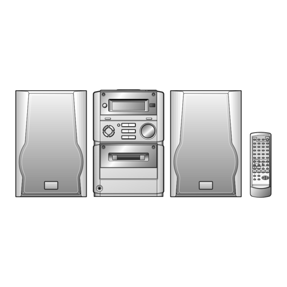
Page 4: Names Of Parts
XL-70V NAMES OF PARTS XL-70V Front panel 1 2 3 1. Timer Indicator 2. Record Indicator 3. Sleep Indicator 4. (VCD/CD) Random Indicator 5. (VCD/CD/TUNER) Memory Indicator 6. FM Stereo Mode Indicator 7. (VCD/CD) Play Indicator 8. (VCD/CD) Repeat Indicator 9. - Page 5 XL-70V Remote control 1. Remote Control Transmitter LED 2. Timer Button 3. (VCD/CD) Audio Mode Button 4. (VCD/CD) Direct Search Buttons 5. (VCD/CD) Display Button 6. (VCD) Video Intro Button 7. Sleep Button 8. On/Stand-by Button 9. (VCD) TV Type Button 10.
-
Page 6: Operation Manual
XL-70V OPERATION MANUAL – 6 –... - Page 7 XL-70V – 7 –...
-
Page 8: Disassembly
XL-70V DISASSEMBLY XL-70V Caution on Disassembly (A1)x1 Follow the below-mentioned notes when disassembling Top Cabinet ø3x10mm the unit and reassembling it, to keep it safe and ensure CD PWB excellent performance: (B2)x1 1. Take cassette tape and compact disc out of the unit. - Page 9 XL-70V CP-XL70U Front Panel STEP REMOVAL PROCEDURE FIGURE Woofer/Tweeter 1. Net Frame ... (A1) x1 2. Screw ....(A2) x4 3. Woofer Ring ..(A3) x1 4. Screw ....(A4) x4 Tape Mechanism Open Tweeter (A1)x1 (A4)x4 Cassette (K1)x4 ø3x12mm Holder ø2.5x10mm...
-
Page 10: Removing And Reinstalling The Main Parts
XL-70V TEST MODE The test mode applied to this microcomputer has three modes, namely ordinary test mode to be used for adjustment or measurement, aging test mode to be used for aging test, and self-diagnosis test mode for self-inspection in case of final product inspection. - Page 11 XL-70V 3. Preset frequencies for various destinations (random preset memory) BAND Ordinary 1, China BAND Ordinary 1, China FM 87.50 MHz FM108.00 MHz FM STEREO FM 98.00 MHz FM 90.00 MHz FM106.00 MHz AM 531 kHz AM1602 kHz AM 990 kHz...
-
Page 12: Adjustment
XL-70V 6. Button input diagnosis Test Mode (TEST 6) When the test mode is set, the following indication appears. This test mode is intended to check whether all the main unit buttons can be detected. Accordingly, in this test mode checking as to whether the "POWER"... - Page 13 XL-70V TAPE mechanism error display (1) Error contents ......Displayed when not becomes "ON" while the mechanism operating detection SW "CAM-SW" is being operated even though the motor or solenoid are controlled to operate the tape for playback/ FF/REW/Recording. Major cause ....... When displayed even though the mechanism is working, failure of CAM-SW and connection failure.
-
Page 14: Notes On Schematic Diagram
XL-70V NOTES ON SCHEMATIC DIAGRAM • Resistor: • The indicated voltage in each section is the one measured To differentiate the units of resistors, such symbol as K and by Digital Multimeter between such a section and the chas- M are used: the symbol K means 1000 ohm and the symbol sis with no signal given. -
Page 15: Voltage
XL-70V VOLTAGE IC802 IC806 IC701 IC14V IC15V NO. VOLTAGE NO. VOLTAGE NO. VOLTAGE NO. VOLTAGE NO. VOLTAGE NO. VOLTAGE NO. VOLTAGE NO. VOLTAGE 2.5V — 2.6V 2.5V 3.6V 3.6V 4.8V 1.3V 2.7V 2.5V 2.5V 2.5V — 3.5V 2.5V 4.8V 2.7V —... -
Page 16: Block Diagram
XL-70V V_GND V_5V REGULATOR Q11V 3.3V IC17V 74HC07A BUFFER AMP. IC10V IX0035SJ ROM 256K x 16 VSSK AUX4 LA12 /BUSY LA13 AUX3/DSASTB LA14 AUX2/DATA LA15 AUX1/DSADATA LA16 AUX0/DSAACK LA17 PCLKQSCN AUDIO_CLK PCLK2XSCN AUDIO_DATA DCLK IC15V BCLK HSYNC ES3880F VSYNC VIDEO CD DECODER... - Page 17 XL-70V IC11V NJM4555M BUFFER AMP. R_CH A_GND L_CH A_12V VDAC V_GND V_AMP Q12V VD_DO VD_DI BUSY VD_STB XL100V 27MHz 27MHz 80 79 78 77 76 75 74 73 72 71 70 69 68 67 66 65 64 63 62 61 60 59 58 57 56 55 54 53 52 51...
- Page 18 XL-70V IC805 LCD701 TA7291S CD MOTOR DRIVER D704-709 COM1 M_GND COM3 COM0 CFW701 TO MAIN PWB VLC3 COM2 M_12V VLC2 VLC1 SWITCHING OSC2 M801 IC701 OSC1 X701 A_12V CD LID MOTOR Q707 LED+B 8MHz IX0030SJ SYSTEM CONT X702 MMOD 32.768kHz...
- Page 19 XL-70V D701 CL ID_SW SEG27 CLID_OUT SEG25 COM3 SEG28 VD_DO COM2 SEG26 SEG29 VD_DI SEG30 BUSY SEG31 SEG32 VD_STB SEG33 CD_STB IC701 CLID_DW IX0030SJ CLID_UP SYSTEM CONTROL CLID_OUT MVOL_DW MICROCOMPUTER MVOL_UP TAPE_SW MVOL_UP A_12V MVOL_IND M_12V SURR IC702 D_GND TA7291S...
- Page 20 XL-70V TUNER AM ANT VD301-1 SVC348S SWITCHING FM MUTE LEVEL T302 R_MUTE Q351 VR351 AM OSC OUT X351 14 13 VD301-2 AM OSC SVC348S T306 10 11 CNP301 AM LOOP ANTENNA AM IF T351 CF351 SO301 CF352 ZD351 FM ANTENNA...
- Page 21 XL-70V R-IN R-OUT FM ST A_12V IC201 DISPLAY PWB CD+B KIA4558P P MUTE Q201 SURROUND P-STB CNS704 CONTROL Q203 L-OUT SUR ON/OFF SO401 L-IN R-CH IC401 A_GND CONT AUX IN LC75342M L-CH FUNCTION/VOLUME SURROUND EQALIZER V-OUT R-CH OUT CNW608 AUX R...
-
Page 22: Schematic Diagram
XL-70V AM TRACKING SWITCHING AM ANT. C330 FM MUTE C343 12P(CH) LEVEL VR351 C332 C331 10K(B) 0.022 VD301 0.047 4.7V T302 SVC348S C371 (0V) L353 R361 C329 D301 1/50 0.022 1N4148 R362 AM BAND COVERAGE fL R323 C372 D302 1/50... - Page 23 XL-70V C212 0.0033 R202 C204 8.2K 1/50 CHING R204 C202 IC201 C214 100K 0.0056 SURROUND 4.7/50 FM SIGNAL CONTROL C216 R218 R206 R212 R214 R216 1/50 2.7K KIA4558P FROM AM SIGNAL VIDEO PWB P29 12-B R208 PLAYBACK SIGNAL CNS607 5.0V 5.0V...
- Page 24 XL-70V LED PWB-A4 SW728 R705 VOLUME/JOG 5.6K CFW701 SW718 SURROUND SW727 R706 FUNCTION 3.9K R7D8 D709 D707 D708 R7D5 R7D3 MPG3372X MPG3372X MPG3372X R718 SW726 SW713 R707 1.5K TUNING DOWN VOLUME SELECT 2.7K D704 D706 D705 R7D1 R7D9 R7D6 MPG3372X...
- Page 25 XL-70V DISPLAY PWB-A2 LCD701 LCD DISPLAY 97 96 95 94 93 92 91 90 89 88 87 86 85 84 83 82 81 80 79 78 77 76 SEG24 SEG25 SEG26 SEG27 SEG28 CLID_DW SEG29 CLID_UP SEG30 CDID_PRO SEG31 CLID_SW...
- Page 26 XL-70V IC805 IC805 CNS809 CD MOTOR VD_DO TA7291S DRIVER VD_DI R837 BUSY CNP809 FROM M801 VD_STB CD LID MOTOR VIDEO PWB CNS804 CNP804 R872 C871 C872 P29 12-C BI809 47/16 (1/2W) C844 R873 5.6K CNP702 CD_STB VD_STB R874 CD LID PWB-A9 2.2K...
- Page 27 XL-70V CD SIGNAL R837 R848 R832 R836 2.2K 11 10 C844 R842 R893 MPACK MECHA R841 R894 TEST MPDATA DATA /RESET R840 R895 MPSTB IC806 R896 IX0031SJ MPRST MPRST XOUT CD SERVO TO MAIN PWB MICROCOMPUTER BI605A CNS605A X802 P23 8-H...
- Page 28 XL-70V Q11V 2SD1858R2 3.6V C105V C125V R143V 100/10 4.3V V_GND CNS810 V_8V FROM CD PWB P27 11-C IC10V C126V IX0035AF C112V ROM 256Kx16 C115V 100/10 PGM/A18 R98V R97V R96V 4.7K 4.7K 4.7K R90V IC17V 14 13 12 11 10 9 8...
- Page 29 XL-70V IC11V C171V R115V 10/25 NJM4565M C144V BUFFER AMP. 33P(CH) C143V R108V R107V R116V C172V 33P(CH) 10/25 A_12V C167V R101V R186V 22P(CH) 100K GND_A R102V 100K R187V R189V R190V R183V 100K CNS607 R111V VDAC R184V 100K GND_V R113V C101V R195V...
- Page 30 XL-70V POWER PWB-B1 D651 D652 1N5402M F651 1N5402M C651 T3.15A L 250V BI651 B1GND R651 680K D653 D654 (3W) 1N5402M 1N5402M D656 230-240V 1N4004 C695 220V C656 C657 0.001 CNS652 BI652 D657 1N4004 B2GND 127V CNP652 110V D658 D659 FROM...
-
Page 31: Wiring Side Of P.w.board
XL-70V FROM CD PWB P34 3-C CNS651 CNS605B MAIN PWB 1 2 3 4 P32 1-A CNP654 BI651 CNP652 Q609 CNS652 1 2 3 4 F652 R651 FROM T1.25A L250V DISPLAY PWB C680 P33 12-F D652 CNS707 C661 C654 C651... - Page 32 XL-70V ANTENNA TERMINALS SO601 AM LOOP SPEAKER ANTENNA FROM SO401 SO301 TERMINALS FROM ANTENNA FM 75 OHMS POWER PWB VIDEO OUT VIDEO/AUX POWER P31 8-A L-CH R-CH AMP.PWB R-CH L-CH CNS652 P31 11-F CNS604 CNP301 C376 C301 E C B...
- Page 33 XL-70V DISPLAY PWB-A2 TO MAIN PWB P36 6-G R746 CNP703 R743 R775 CNS702 R741 1 2 3 4 5 6 7 8 9 10 11 12 R779 SW710 R701 CNS703 R740 R702 CLOCK/ R756 R750 R739 SW722 SW709 TIMER/ BASS/...
- Page 34 XL-70V NM801 SLED MOTOR CD MOTOR PWB-C NM802 F3895AF SPINDLE MOTOR NSW801 OPEN/CLOSE PICKUP IN SWITCH PWB-A6 TO MAIN PWB P32 6-E CFW807 CNP605 SW730 M801 OPEN/ CD LID CLOSE MOTOR PICKUP UNIT (306) CNS605A CNS803 1 2 3 4 5 6...
- Page 35 XL-70V : Through-hole where the top and bottom patterns are connected. C169V R90V R171V IC17V R97V R98V C136V COLOR TABLE R143V R91V R194V C150V R96V BROWN R137V R111V R112V R178V R138V RD(R) C105V R93V R139V ORANGE R141V C131V YELLOW R140V...
-
Page 36: Function Table Of Ic
XL-70V FUNCTION TABLE OF IC IC701 RH-iX0030SJZZ: System Control Microcomputer (IX0030SJ) (1/2) Pin No. Terminal Name Port name Input/Output Function COM3-COM0 COM3-COM0 Output LCD common output terminal. VLC3-VLC1 VLC3-VLC1 — LCD power terminal. — Microcomputer power +5V. OSC2 OSC2 Output Oscillator connecting terminal for main clock. - Page 37 XL-70V IC701 RH-iX0030SJZZ: System Control Microcomputer (IX0030SJ) (2/2) Pin No. Terminal Name Port name Input/Output Function LED2 CS/P52 B-CAN Output Recording bias oscillation frequency selection control output. LDE3/S51 A16/P53 SURR Output SURROUND control output. "L" = Surround ON "H" = Surround OFF...
-
Page 38: Lcd Segment
XL-70V LCD SEGMENT LCD701: RV-LX0007SJZZ 1 2 3 4 5 6 7 8 9 10 11 12 13 14 15 16 17 18 19 20 21 22 23 24 25 26 27 28 29 30 31 32 33 34 35 36 37 38 39 40 41 42... - Page 39 PARTS GUIDE VIDEO CD MICRO SYSTEM XL-70V MODEL XL-70V Video CD Micro System consisting of XL-70V (main unit) and CP-XL70U (speaker system). “HOW TO ORDER REPLACEMENT PARTS” To have your order filled promptly and correctly, please furnish the For U.S.A. only following information.
- Page 40 XL-70V PRICE PRICE DESCRIPTION PARTS CODE PARTS CODE DESCRIPTION RANK RANK D411,412 VHD1N4148//-1 AA Silicon,1N4148 XL-70V D601~603 VHD1N4148//-1 AA Silicon,1N4148 D611~614 VHD1N4004//-1 AB Silicon,1N4004 INTEGRATED CIRCUITS D651~654 VHD1N5402M/-1 AE Silicon,1N5402M D656~659 VHD1N4004//-1 AB Silicon,1N4004 D661~664 VHD1N4004//-1 AB Silicon,1N4004 IC10V RH-IX0035SJZZ ROM 256K×16,IX0035SJ...
-
Page 41: Waveforms Of Cd Circuit
XL-70V PRICE PRICE PARTS CODE DESCRIPTION PARTS CODE DESCRIPTION RANK RANK C103,104 VCKYTV1HB331K AA 330 pF,50V C334 VCCUPA1HJ270J AA 27 pF (UJ),50V AB 100 µF,10V,Electrolytic C104V RC-GZA107AF1A C335 VCKYTV1HB561K AA 560 pF,50V AA 0.022 µF,25V C105,106 VCKYTV1HB271K AA 270 pF,50V... -
Page 42: Troubleshooting (Cd Section)
XL-70V PRICE PRICE PARTS CODE DESCRIPTION PARTS CODE DESCRIPTION RANK RANK AB 10 µF,16V,Electrolytic C673 RC-GZA106AF1C VRS-TV2AB000J AA 0 ohm,Jumper,1.25×2mm,Green AB 0.1 µF,50V,Thin Film C674 VCFYHU1HA104J R7A0 VRS-TV2AB103J AA 10 kohm,1/10W AB 10 µF,16V,Electrolytic C675 RC-GZA106AF1C R7A1 VRS-TV2AB102J AA 1 kohm,1/10W AB 0.1 µF,50V,Thin Film... - Page 43 XL-70V PRICE PRICE DESCRIPTION PARTS CODE DESCRIPTION PARTS CODE RANK RANK R162V VRS-TV2AB472J AA 4.7 kohms,1/10W R613,614 VRD-RT2HD271J AA 270 ohms,1/2W R163V VRS-TV2AB330J AA 33 ohms,1/10W R615,616 VRD-ST2CD472J AA 4.7 kohms,1/6W R164V,165V VRS-TV2AB100J AA 10 ohm,1/10W R617 VRS-TV2AB333J AA 33 kohms,1/10W...
- Page 44 XL-70V PRICE PRICE DESCRIPTION PARTS CODE PARTS CODE DESCRIPTION RANK RANK R872 VRD-RT2HD2R2J AA 2.2 ohms,1/2W M901(237-9) 9GD192112344 AY Motor with Pulley [Tape] R873 VRD-ST2CD562J AA 5.6 kohms,1/6W NM801 RMOTV0409AFM1 J AN Motor with Gear [Sled] R874 VRS-TV2AB222J AA 2.2 kohms,1/10W...
- Page 45 237- 1 94R19210703 AE Belt,FF/REW TLABZ0009SJZZ AD Label,Made in China 237- 2 9GD19210943 AG Belt,Main TLABZ0011SJZZ AD Label,SHARP Japan 237- 3 94R192104309 AG Pinch Roller Arm Ass’y TLABZ0012SJZZ AC Label,SHARP Corporation 237- 4(SOL901 9GD19212118 AP Solenoid Ass’y TLABZ0015SJZZ AC Label,VJ No.
- Page 46 XL-70V XL-70V 306-2 306-1 306-3 703x2 NM802 NM801 305x2 NSW801 PWB-C Figure 7 CD MECHANISM EXPLODED VIEW – 7 –...
- Page 47 XL-70V XL-70V 615x2 PWB-A8 614x2 BELT CONNECTION 216-2 216-1 616x5 Motor(M901) FF/REW PWB-A6 Clutch 603x2 Main Belt PWB-A10 FF/REW 601x3 Flywheel Belt PWB-A7 PWB-A9x3 MECHANISM 610x2 PWB-A4 PWB-A2 PWB-A3 603 601x2 M701 608x2 LCD701 608x2 609x3 M801 609x2 610x2 601x3...
- Page 48 (N.P.) WOOFER SP601(L-CH) SP602(R-CH) SPEAKER EXPLODED VIEW © COPYRIGHT 2000 BY SHARP CORPORATION SHARP CORPORATION ALL RIGHTS RESERVED. Communication Systems Group Quality & Reliability Control Center No part of this publication may be reproduced, Higashihiroshima, Hiroshima 739-0192, Japan stored in a retrieval system, or transmitted in...