
Related Manuals for Mitsubishi Electric RD81RC96-CA


Summary of Contents for Mitsubishi Electric RD81RC96-CA
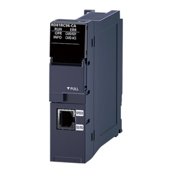
- Page 1 Mitsubishi Electric Programmable Controller Camera Recorder Module RD81RC96-CA Sample Screen Manual Mitsubishi Electric Corporation...
- Page 2 Mitsubishi Electric products. (4) Mitsubishi Electric will not be held liable for any damages resulting from the use of the Files or the data extracted from the Files. The customer is responsible for all use.
-
Page 3: Table Of Contents
CONTENTS REVISIONS ..................................5 OUTLINE ................................6 SYSTEM CONFIGURATION ..........................6 Supported GOT ............................. 6 Necessary Equipment ........................... 6 Connection Configuration ..........................7 PROJECT SPECIFICATION ..........................8 System Application ............................8 Controller Setting ............................8 GOT Ethernet Setting ............................ 9 FTP Server Setting ............................9 Graphics Mode (Graphics Setting) ...................... - Page 4 IP Address Setting of the PC ........................52 How to Change to Ethernet Module Connection..................53 Controller Setting of the GOT ......................53 PLC Side Setting (GX Works3) ......................54 Procedure for Changing the Timeout Time ....................55 TROUBLESHOOTING ............................56 Troubleshooting Related to GOTs........................ 56 Troubleshooting Related to PLCs ........................
-
Page 5: Revisions
REVISIONS ■Sample Screen Manual Date Control No.* Description 2021/1 BCN-P5999-1333 First edition 2021/4 BCN-P5999-1333-1a The default value of the number of FTP clients has been changed to 4. 2021/7 BCN-P5999-1333-2 Simple setting mode of network cameras is supported. The explanations are added to 2 of 3.4. FTP Server Setting. 2021/8 BCN-P5999-1333-2a 7.8 Procedure for Changing the Timeout Time has been added. -
Page 6: Outline
This manual explains the sample screens of GOT2000 connected to MELSEC iQ-R series camera recorder module RD81RC96-CA used for live feed, PTZ control and preset function of the network camera video. The sample screens make startup of equipment easier because they enable you to adjust shooting range of the network camera by the GOT. -
Page 7: Connection Configuration
Ethernet cable *1 *1: For details on the cable, please refer to the manual below. ⇒"GOT2000 Series Connection Manual (Mitsubishi Electric Products)" *2: The maximum number of network cameras can be connected to one camera recorder module is 4. For details, please refer to "MELSEC iQ-R System Recorder User's Manual (Startup)". -
Page 8: Project Specification
3. PROJECT SPECIFICATION 3.1 System Application Type System Application Name Standard System Application Standard Function Standard Font Japanese Communication Driver Ethernet Connection Ethernet (MITSUBISHI ELECTRIC), Gateway Standard Font Chinese (Simplified) Alphanumeric/Kana Outline Font Gothic Japanese Kanji Extended Function Chinese (Simplified) Kanji... -
Page 9: Got Ethernet Setting
3.3 GOT Ethernet Setting ■GOT IP Address Setting Port Item Set Value Remarks Standard Port Update GOT Ethernet Standard Port setting Checked 192.168.3.18 GOT IP Address Subnet Mask 255.255.255.0 Extended Port None None Wireless LAN ■GOT Ethernet Common Setting Item Set Value Remarks Default Gateway... - Page 10 2. How to perform the setting of FTP server of GT SoftGOT2000 and MELIPC MI3000 (Windows10) (1) Installation of IIS Go to "Control Panel" - "Programs and Features" to select "Turn Windows features on or off", and check the following items of "Internet Information Services". Item Set Value Remarks...
- Page 11 (3) Restart of FTP Service Go to "Control Panel" - "Administrative Tools" to select "Services" and restart the service from "Microsoft FTP Service". (4) Folder creation of FTP site Create any folder (Example: C/inetpub/ftproot) or open "Install folder/MELSOFT/SGT2000/Multi/00001/Drive" (*1) to create the "V" folder. *1 For folders in "Install folder/MELSOFT", there is a possibility that access authorities given when installing MELSOFT products are not given.
- Page 12 (5) Setting of FTP site Go to "Control Panel" - "Administrative Tools" to select "Internet Information Services (IIS) Manager". Right-click "Sites" to select "Add FTP site". computer name computer name (6) Site Information Set "ftp (user-defined name)" in FTP site name and the folder created in (4) (Example: C/inetpub/ftproot or Install folder/MELSOFT/SGT2000/Multi/00001/Drive/V) in Physical path.
- Page 13 (7) Binding and SSL setting Set "21 (cannot be changed)" to Port in Binding and "No SSL" to SSL. (8) Authentication and Authorization information Check "Basic" in Authentication and set "All users" to Allow access to in Authorization. Check "Read" and "Write"...
- Page 14 (9) Addition of FTP user Right-click "Start" to open "Computer Management" in the menu. Then, click "System Tools" - "Local Users and Groups" - "Users". Select "Action" in the menu bar - "New User", and then input User name and Password. After that, click "Create".
- Page 15 Click "Locations". computer name Select the computer name for registering the user. computer name Input "(User name set in (9) Addition of FTP user)" to "Enter the object names to select" and then click "Check Names" to check the name is determined. After the check, click "OK". computer name Click "Apply"...
- Page 16 (10) Authority setting of file storage location Right-click the physical path set in (6) Site Information (Example: C/inetpub/ftproot or Install folder/MELSOFT/SGT2000/Multi/00001/Drive/V) and click "Properties" to open "Security" tab and then click "Edit". Click "Add". Select the location and then input "User name set in (9) Addition of FTP user". After that, click "Check Names" and then "OK".
- Page 17 Check "Full control" in Permissions and then click "OK". ftpUSER (MEIA8858/ftpUSER) computer name ftpUSER (MEIA8858/ftpUSER) (11) Change of the virtual V drive folder of GT SoftGOT2000 [Only when setting FTP site to a folder other than "Install folder/MELSOFT/SGT2000/Multi/00001/Drive/V] Start GT SoftGOT2000 and open "Set"- "Environment Setup" to set Path of V Drive in Virtual Drive Setting to the physical path set in (6) Site Information (Example: C¥inetpub¥ftproot).
-
Page 18: Graphics Mode (Graphics Setting)
3.5 Graphics Mode (Graphics Setting) GOT Graphic Ver.2 is used as graphics setting. 3.6 Data Type of Screen Switching Device Data type of screen switching device is BIN. 18/59 BCN-P5999-1333-2a... -
Page 19: Device List
3.7 Device List Some of the devices set to the on-screen switches and lamps, etc., are also used for common settings of functions such as scripts. Using [Batch Edit] is recommended to change these devices in a batch. For the details on [Batch Edit], please refer to "GT Designer3 (GOT2000) Screen Design Manual". -
Page 20: Label (Gt Desinger3)
Label (GT Desinger3) ■Label group No.200 Com_Label Assigned (Device) Label name Data type Application Default value Script trigger for language GT_b_Com_TrigScrKeepLng GB30000 holding Script trigger for clock GT_b_Com_TrigScrSetTim GB30001 setting at startup Alarm common setting GB30002 GT_b_Com_AlmComSetConvTrig conversion trigger device Notification device during GB30003 GT_b_Com_AlmSetConvNtcDv... -
Page 21: Comment
Recipe common setting GT_u16_Com_RcpCmCntlDv Unsigned BIN16 [0..2] GD30090 External control information Recipe common setting External notification GT_u16_Com_RcpCmNtcDv Unsigned BIN16 [0..2] GD30093 information Station number switching GT_u16_Com_StChgDv Unsigned BIN16 GD30096 device Alarm Common Setting GT_u16_Com_AlarmIDDv Unsigned BIN16 GD30097 Alarm ID GT_u16_Com_LabelResolve Unsigned BIN16 GD30098 Label resolution work device... -
Page 22: Script
3.9 Script Item Script No./Object ID Setting Screen Yes (No.32000,32001,32002 and 32003) Project script Screen script Object script Yes (Placed on the upper left of each B-32001 to 32004 and B-32006 Script parts screen) ■Location of Script Parts Example: Controller Selection screen (B-32001) Script part 22/59 BCN-P5999-1333-2a... -
Page 23: Plc Side Setting (Gx Works3)
4. PLC SIDE SETTING (GX WORKS3) 4.1 Setting of Camera Recorder Module (1) Settings of module parameter [Module Information] - [RD81RC96-CA] - [Module Parameter] - [Basic Settings] - [Own Node Settings] Item Set value Various Operations Settings Online Specify IP Address... -
Page 24: Screen Specifications
5. SCREEN SPECIFICATIONS 5.1 Screen Specifications This section explains the details of the screens in this sample screen. Common Items of Each Screen Outline Functions and settings common in each screen are described. Description Notifies the user about errors related to the connection to the camera recorder module. Lights red when an error is occurring. -
Page 25: Controller Selection (B-32001)
Controller Selection (B-32001) Outline This screen is used to select the monitor target camera recorder module and the network camera. Description Selects the module to which the monitor target network camera is connected. Only one module can be selected. When selecting another module, deselect the module which is currently being selected. -
Page 26: Live Feed Settings (B-32002)
Live Feed Settings (B-32002) Outline This screen is used to perform the settings of live feed. Description Displays No. and the comments of the network camera selected in the Controller Selection screen. Selects the video quality of the live feed. *1 Update cycle of the live feed changes depending on the selected video quality. - Page 27 screen. Contents Warnings Resolution not supported The resolution of the target network camera is not supported. Connect a camera with the supported resolution. PTZ not supported PTZ control and preset function cannot be used because PTZ control is not supported by the network camera. Z not supported PTZ control of the axis Z and preset function cannot be used because Z control is not supported by the network camera.
-
Page 28: Live Feed (B-32003)
Live Feed (B-32003) Outline This screen is used for live feed on the GOT. Description Displays No. and the comments of the network camera selected in the Controller Selection screen. Displays the network camera video after starting the live feed. Resolution of the video is different depending on sample project data as below. - Page 29 ・Functions can be operated are different depending on the operation mode of the camera recorder module. Please refer to the table below. Operation mode PTZ control Preset registration Preset execution ○ ○ ○ PTZ enabled mode ○ PTZ preset mode ×...
-
Page 30: Preset Position List (B-32004)
Preset Position List (B-32004) Outline This screen is used to set preset positions. Description Displays No. and the comments of the network camera selected in the Controller Selection screen. Displays the current PTZ values. Switches the preset position list. Displays the information of the preset positions. : No. -
Page 31: Connection Error Notification (B-32005)
Connection Error Notification (B-32005) Outline This screen is used to check errors related to the connection to the camera recorder module. Description Displays the information of the network camera selected in the Controller Selection screen. The information does not switch in accordance with the language switching of the GOT. Displays the details of the current error and the corrective action. -
Page 32: Option Settings (B-32006)
Option Settings (B-32006) Outline This screen is used to change the language displayed on the GOT and the GOT clock data. Description Switches the language by touching the switches. Displays the current date and time. Sets the date and time with switches. -
Page 33: System Alarm (Got) (B-32007)
System Alarm (GOT) (B-32007) Outline This screen is used to check current system alarms of the GOT. Description Displays maximum 12 current system alarms. Touching the displayed system alarm scrolls the message. Switches to the screen which was previously displayed. Resets the current system alarms. -
Page 34: Utilize Sample Screen
6. UTILIZE SAMPLE SCREEN This section explains how to incorporate this sample screen in the customer’s project data (hereafter utilize) in the system configuration below. When utilizing this sample screen, apply the system configuration below to the customer's system configuration. Example: When adding this sample screen to the customer's project data which sets the MELSEC iQ-R CPU to the connected controller CH1 Ethernet cable... -
Page 35: Checks Before Utilization
6.1 Checks Before Utilization Check and perform the items below before utilizing the sample screen. GT27/25 SoftGOT (1) Backup The settings of the customer's project data are changed by utilizing this sample screen. Make sure to back up the project data before utilizing this sample screen. (2) Change of GOT internal devices and labels (GT Designer3) GT27/25 SoftGOT... -
Page 36: Utilization Procedure
6.2 Utilization Procedure After performing "6.1 Checks Before Utilization", utilize this sample screen in accordance with the procedures below. (1) Open this sample screen. Customers who have installed this sample screen from the installer of GT Works3 *1 ⇒ "6.2.1 How to Open the Sample Screen Installed to GT Designer 3" (2) Perform the settings below. -
Page 37: How To Open The Sample Screen Installed To Gt Designer3
GT27/25 SoftGOT How to Open the Sample Screen Installed to GT Designer3 Select [Project] and then [Utilize Data] and perform the operations below to open the sample screen. (1) Set "Sample project" to [Target]. (2) Select [Detail>>] and input " RD81RC96 " to [Keyword]. Then select [Search]. (3) Select [OK]. -
Page 38: Preparation Before Utilization
GT27/25 SoftGOT Preparation before Utilization Change the settings of the sample screen in accordance with the procedures below. (1) Refer to "7.1 How to Change Resolution" and select the sample project for using. (2) Refer to "7.2 Changing the Communication Settings of PLCs from CH1 in [Controller Setting]", and set script symbols. -
Page 39: Utilize Project
GT27/25 SoftGOT Utilize Project Utilize the project data created in "6.2.2 Preparation before Utilization" in the customer's project data in accordance with the procedures below. (1) Open the customer’s project data with GT Designer3. (2) Select [Project] and then [Utilize Project]. (3) Select [Browse] and open the project data created in "6.2.2 Preparation before Utilization". - Page 40 (5) Set [Retain the same No.] in [Destination], and select [Utilize]. (6) Perform "6.3 Works after Utilization". When using GT SoftGOT When using multiple channels for controllers, select [GT SoftGOT2000 (Multi-channel)] at startup. 40/59 BCN-P5999-1333-2a...
-
Page 41: Works After Utilization
GT27/25 SoftGOT 6.3 Works after Utilization In this sample screen, functions of the settings need to be added and changed in accordance with the customer's system configuration after utilization. Please refer to the items below for works after utilization. ⇒"6.3.1 Settings of labels (GT Designer3)" ⇒"6.3.2 GOT Environmental Setting"... -
Page 42: Got Environmental Setting
GT27/25 SoftGOT GOT Environmental Setting Change and add the settings below in the project data after utilization [Screen Switching / Window Setting] ■Base Screen Change the screen switching device of [Base Screen] as the table below. Item Setting $Com_Label:GT_u16_Com_CngBsDv [Screen Switching Device] 42/59 BCN-P5999-1333-2a... - Page 43 (2) [Language Switching] Language switching is supported in this sample screen. When using language switching, go to [Common] - [GOT Environmental Setting] - [Language Switching] to open the setting screen and set the items below. When not using language switching, the settings are not required. Please refer to "3.8 Comment"...
-
Page 44: Precautions For Screen Switching
(3) [System Information] In this sample screen, the switch which can reset the current system alarms of the GOT is set. When using the reset function of system alarms, go to [Common] - [GOT Environmental Setting] - [System Information] to open the setting screen and set the items below. When not using the reset switch of system alarms, the settings are not required. -
Page 45: Customize
7. CUSTOMIZE GT27/25 SoftGOT 7.1 How to Change Resolution When using the sample screen in a GOT with resolution not listed in "2.1 Supported GOT", follow the procedures below. (1) Refer to the table below and select the project for using. Resolution of the GOT Sample project data Resolution of video... -
Page 46: Changing The Communication Settings Of Plcs From Ch1 In [Controller Setting]
GT27/25 SoftGOT 7.2 Changing the Communication Settings of PLCs from CH1 in [Controller Setting] In this sample screen, statuses of PLCs are monitored by connecting PLCs to the channel No.1 of the GOT. When connecting PLCs to the channels other than the channel No.1, change the settings as below. ■Setting Example: When connecting PLCs to the channel No.2 (1) Select CH2 in the [Controller Setting] tree and add the controller setting. - Page 47 (3) Go to [Script] - [Script Symbol] to set the channel No. of the PLC on which the camera recorder module is installed to the script symbol. 47/59 BCN-P5999-1333-2a...
-
Page 48: How To Change Network No. And Station No. Of Plcs
GT27/25 SoftGOT 7.3 How to Change Network No. and Station No. of PLCs In this sample screen, statuses of PLCs whose network No. and station No. are 1 are connected and monitored. When connecting PLCs whose network No. or station No. is other than the above setting, change the settings as below. - Page 49 (3) Go to [Script] - [Script Symbol] to set the network No. and the station No. of the PLC on which the camera recorder module is installed to the script symbol. No.9150:Network No. No.9151:Station No. 49/59 BCN-P5999-1333-2a...
-
Page 50: Changes Of I/O Assignment Of The Camera Recorder Module
7.4 Changes of I/O Assignment of the Camera Recorder Module The setting example is as below. GT27/25 SoftGOT ■Setting of GX Works3 Go to [Parameter] - [System Parameter] - [I/O Assignment] to check Start XY of the camera recorder module. ■Setting of GT Designer3 Go to [Script] - [Script symbol] to set the start XY of the camera recorder module to the script symbol. -
Page 51: How To Change The Number Of Ftp Clients
GT27/25 7.5 How to Change the Number of FTP Clients In this sample screen, the camera recorder module operates as an FTP client by using the FTP server function of the GOT. Therefore, the number of simultaneously connectable clients needs to be changed when other FTP clients are already connected. -
Page 52: Ip Address Setting Of The Pc
SoftGOT 7.6 IP Address Setting of the PC When using GT SoftGOT or MELIPC MI3000, register the IP address of the PC as script parts symbols. ■Setting Example: When the IP address of the PC is "192.168.3.100". (1) Select the script part placed on the upper left of the Controller Selection screen (B-32001). (2) Register the IP address of the PC as below. -
Page 53: How To Change To Ethernet Module Connection
*2 *1: For details on the cable, please refer to the manual below. ⇒"GOT2000 Series Connection Manual (Mitsubishi Electric Products)" *2: The maximum number of network cameras can be connected to one camera recorder module is 4. For details, please refer to "MELSEC iQ-R System Recorder User's Manual (Startup)". -
Page 54: Plc Side Setting (Gx Works3)
■GOT IP Address Setting Port Item Set Value Remarks Standard Port Update GOT Ethernet Standard Port setting Checked 192.168.3.18 GOT IP Address 255.255.255.0 Subnet Mask None Extended Port Wireless LAN None ■GOT Ethernet Common Setting Item Set Value Remarks Default Gateway 0.0.0.0 Peripheral S/W Communication Port No. -
Page 55: Procedure For Changing The Timeout Time
GT27/25 SoftGOT 7.8 Procedure for Changing the Timeout Time Depending on the network camera, the response to the start of live feed may be slow, and as a result, the start of live feed may fail due to a communication timeout. In that case, follow the procedure below to extend the timeout time. -
Page 56: Troubleshooting
8. TROUBLESHOOTING Troubleshooting of this sample screen is explained below. 8.1 Troubleshooting Related to GOTs (1) System alarm "535 Cannot open image file." occurs. Cause Countermeasure The specified file does not exist in the The image file is not stored. Check that there is no problem drive. -
Page 57: Troubleshooting Related To Plcs
8.2 Troubleshooting Related to PLCs (1) Errors which store error codes Refer to the table below and take the countermeasure against the displayed error code. Cause Countermeasure Disable is set to the GOT linkage enable / Set enable to the GOT linkage enable / disable in the disable in the module extended parameter module extended parameter of the selected camera of the selected camera recorder module. -
Page 58: Precautions
9. PRECAUTIONS Precautions of this sample screen is explained below. (1) Switching from the user screen When switching from the user screen to this sample screen, make sure to switch via the Controller Selection screen (B-32001). When switching without switching to the Controller Selection screen (B-32001), there is a possibility that the sample screen does not operate correctly. -
Page 59: Trademarks
10. TRADEMARKS MELDAS, MELSEC, iQ Platform, MELSOFT, GOT, CC-Link, CC-Link/LT, and CC-Link IE are trademarks or registered trademarks of Mitsubishi Electric Corporation in Japan and other countries. Ethernet is a registered trademark of Xerox Corporation in the United States. Other company and product names herein are trademarks or registered trademarks of their respective owners.