
Related Manuals for Mitsubishi Electric RD81DL96


Summary of Contents for Mitsubishi Electric RD81DL96
- Page 1 MELSEC iQ-R High Speed Data Logger Module User's Manual (Startup) -RD81DL96 -SW1DNN-RDLUTL (High Speed Data Logger Module Tool)
-
Page 3: Safety Precautions
SAFETY PRECAUTIONS (Read these precautions before using this product.) Before using this product, please read this manual and the relevant manuals carefully and pay full attention to safety to handle the product correctly. The precautions given in this manual are concerned with this product only. For the safety precautions for the programmable controller system, refer to the user's manual for the module used and the MELSEC iQ-R Module Configuration Manual. - Page 4 [Design Precautions] WARNING ● Configure safety circuits external to the programmable controller to ensure that the entire system operates safely even when a fault occurs in the external power supply or the programmable controller. Failure to do so may result in an accident due to an incorrect output or malfunction. (1) Emergency stop circuits, protection circuits, and protective interlock circuits for conflicting operations (such as forward/reverse rotations or upper/lower limit positioning) must be configured external to the programmable controller.
- Page 5 [Design Precautions] WARNING ● Do not write any data to the "system area" and "write-protect area" of the buffer memory in the module. Also, do not use any "use prohibited" signals as an output signal from the CPU module to each module.
-
Page 6: Wiring Precautions
[Installation Precautions] WARNING ● Shut off the external power supply (all phases) used in the system before mounting or removing the module. Failure to do so may result in electric shock or cause the module to fail or malfunction. [Installation Precautions] CAUTION ●... - Page 7 [Wiring Precautions] CAUTION ● Individually ground the FG and LG terminals of the programmable controller with a ground resistance of 100 ohms or less. Failure to do so may result in electric shock or malfunction. ● Use applicable solderless terminals and tighten them within the specified torque range. If any spade solderless terminal is used, it may be disconnected when the terminal screw comes loose, resulting in failure.
- Page 8 [Wiring Precautions] CAUTION ● Programmable controllers must be installed in control panels. Connect the main power supply to the power supply module in the control panel through a relay terminal block. Wiring and replacement of a power supply module must be performed by qualified maintenance personnel with knowledge of protection against electric shock.
- Page 9 [Startup and Maintenance Precautions] CAUTION ● When connecting an external device with a CPU module or intelligent function module to modify data of a running programmable controller, configure an interlock circuit in the program to ensure that the entire system will always operate safely. For other forms of control (such as program modification, parameter change, forced output, or operating status change) of a running programmable controller, read the relevant manuals carefully and ensure that the operation is safe before proceeding.
- Page 10 [Startup and Maintenance Precautions] CAUTION ● Before handling the module, touch a conducting object such as a grounded metal to discharge the static electricity from the human body. Failure to do so may cause the module to fail or malfunction. [Operating Precautions] CAUTION ●...
-
Page 11: Conditions Of Use For The Product
CONDITIONS OF USE FOR THE PRODUCT (1) Mitsubishi programmable controller ("the PRODUCT") shall be used in conditions; i) where any problem, fault or failure occurring in the PRODUCT, if any, shall not lead to any major or serious accident; ii) where the backup and fail-safe function are systematically or automatically provided outside of the PRODUCT for the case of any problem, fault or failure occurring in the PRODUCT. -
Page 12: Considerations For Use
CONSIDERATIONS FOR USE This section explains the following considerations. Page 10 Considerations for network connection Page 10 Considerations for performance/specifications Page 11 Considerations for data logging, event logging, and report functions Page 12 Considerations for other functions Page 12 Considerations for accessing a high speed data logger module Page 13 Considerations for security Page 13 Considerations for using SD memory cards Page 15 Considerations for the recipe function... - Page 13 Considerations for data logging, event logging, and report functions ■Data logging, event logging, and report functions • The data logging, event logging, and report functions are best effort functions. Since the processing time of a module varies depending on the setting and the status of other devices, these functions may not perform at the set sampling interval. Run the system by fully verifying the processing time of each function when constructing it.
- Page 14 • When using Microsoft Excel 2010 (32-bit version), Microsoft Excel 2013 (32-bit version), or Microsoft Excel 2016 (32-bit version), install Visual Basic for Applications (abbreviated as VBA below). If VBA is not installed, the error message below is displayed when the "Layout setting" screen is started, and layout settings cannot be configured. "This workbook has lost its VBA Project, ActiveX Controls and any other programmability-related features."...
- Page 15 ■SD memory card to be used • Use SD memory cards manufactured by Mitsubishi Electric Corporation. If any other SD memory cards are used, a failure such as data corruption on the SD memory card or a system shutdown (module major error (error code: 2450H) occurs in the CPU module) may occur during an operation.
- Page 16 ■When removing or replacing the SD memory card • Make sure to stop file access before removing or replacing the SD memory card. (Page 65 File access stop processing method) • Not following the procedure may cause a loss of logging data during processing, corruption of data in the SD memory card that is being accessed, a file system error, or false recognition of the mounting status of the SD memory card.
- Page 17 ■SD memory card life span (Limit on writing) • An SD memory card has a limited life span (limit on writing). For details, refer to the following manual. (MELSEC iQ-R High Speed Data Logger Module User's Manual(Application)) ■RECIPE folder • The maximum number of recipe files that can be stored in the RECIPE folder is 256. Storing large numbers of files in the RECIPE folder causes a longer processing time for the following operations.
-
Page 18: Introduction
The program examples shown in this manual are the examples in which the high speed data logger module (RD81DL96) is assigned to the input/output No. X/Y0 to X/Y1F unless otherwise specified. To use the program examples shown in this manual, the input/output number assignment is required. For details on the assignment of input/output number, refer to the following manual. -
Page 19: Table Of Contents
CONTENTS SAFETY PRECAUTIONS ..............1 CONDITIONS OF USE FOR THE PRODUCT . - Page 20 System configuration for the initial setup, maintenance, and inspection ....... 68 System configuration during operation .
-
Page 21: Relevant Manuals
RELEVANT MANUALS Manual name [manual number] Description Available form MELSEC iQ-R High Speed Data Logger Module Explains the specifications, procedures before operation, wiring, and operation Print book User's Manual(Startup) examples of high speed data logger modules. e-Manual [SH-081561ENG] (this manual) MELSEC iQ-R High Speed Data Logger Module Explains the functions, configuration tool, parameter setting, troubleshooting, I/ Print book... -
Page 22: Terms
An abbreviation for GX LogViewer Version 1. High speed data logger module An abbreviation for MELSEC iQ-R series-compatible RD81DL96 high speed data logger module. High speed data logger module tool An abbreviation for the high speed data logger module tool (SW1DNN-RDLUTL). -
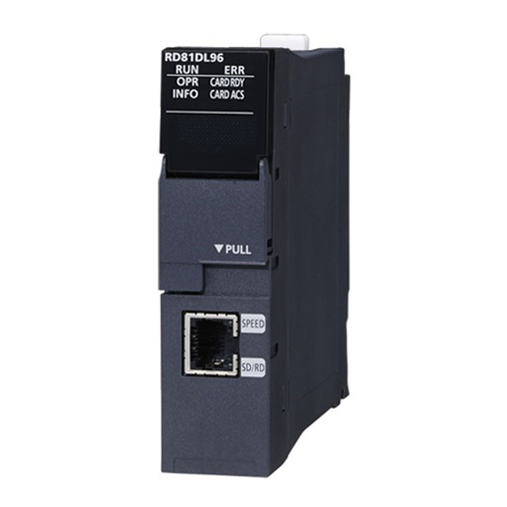
Page 23: Chapter 1 Part Names
PART NAMES This chapter shows the part names of a high speed data logger module. Name Description RUN LED Indicates the operating status. • ON: In operation • Flashing: Checking module, selecting the module for online module change (Flashes for 10 seconds in "Checking module" when the [Checking module] button is pressed on the "Find High Speed Data Logger Module"... - Page 24 Name Description Ethernet port A port for connecting a high speed data logger module to 10BASE-T/100BASE-TX/1000BASE-T (High speed data logger modules distinguish among 10BASE-T, 100BASE-TX, and 1000BASE-T according to an external device.) SD memory card lock switch A switch for disabling access to an SD memory card to remove it. (SD CARD OFF button) Removing an SD memory card is prohibited while the CARD RDY LED is ON or flashing.
-
Page 25: Chapter 2 Specifications
SPECIFICATIONS This chapter explains the performance specifications and accessible devices/device range of a high speed data logger module. Performance Specifications The following table shows the performance specifications of a high speed data logger module. Transmission and interface specifications Item Specification Ethernet Interface 1000BASE-T... -
Page 26: Functional Specifications
Functional specifications Data sampling performance specifications The following table lists the specifications for the data sampling used for the data logging function, the event logging function, and the report function. Item Specifications Data sampling Number of access target CPUs Maximum 64 CPUs Sampling interval High speed sampling •... - Page 27 *1 The number of device points available for a piece of data differs depending on the data type. *2 The total number of sampling data of data logging, event logging, and report data. *3 The total number of units of sampled data per setting is as follows only when the creation trigger and current value data are not synchronized in the report setting.
- Page 28 Data logging performance specifications Item Specifications Data logging Number of settings Up to 64 Logging type • Continuous logging • Trigger logging (output only one line after triggering) • Trigger logging (output the lines before and after triggering) File format •...
- Page 29 Item Specifications Data logging Number of saved files 1 to 65535 ■Simple setting Saved file name • Add the name • Add the date (4-digit year, month, day) • Add the time (hour, minute, second) • Add the sequential number ■Detailed setting •...
- Page 30 Event logging performance specifications Item Specifications Event logging Number of settings Up to 64 Number of events Up to 256 per event logging setting File format • Unicode text file (extension: .TXT) • CSV file (extension: .CSV) • Binary file (extension: .BIN) Event condition Event condition •...
- Page 31 Item Specifications ■Simple setting Event logging Saved folder name • Add the name • Add the date (4-digit year, month, day) • Add the time (hour, minute, second) • Add the sequential number ■Detailed setting • 4-digit year/2-digit year, month, day, day of the week, hour, minute, second •...
- Page 32 Report function performance specifications Item Specifications Report Number of settings Up to 64 File format Excel file (extension: .xls) Output data type • Data inside data logging file • Current value data • Creation time Number of units of output data 64 layouts per report setting, 65535 cells in total Creation trigger Trigger condition...
- Page 33 Item Specifications ■Simple setting Report Saved folder name • Add the name • Add the date (4-digit year, month, day) • Add the time (hour, minute, second) • Add the sequential number ■Detailed setting • 4-digit year/2-digit year, month, day, day of the week, hour, minute, second •...
- Page 34 Item Specifications Recipe Number of units of data Up to 256 data Number of records Up to 256 records Data type • Bit • Word [Signed] • Double Word [Signed] • Word [Unsigned]/Bit String [16-bit] • Double Word [Unsigned]/Bit String [32-bit] •...
-
Page 35: Accessible Routes And Devices
Accessible Routes and Devices This section shows the accessible routes and devices. Accessible CPU modules Series Model Data sampling method RCPU Programmable controller R00CPU , R01CPU , R02CPU , R04CPU, R04ENCPU, R08CPU, • High speed sampling R08ENCPU, R16CPU, R16ENCPU, R32CPU, R32ENCPU, R120CPU, •... -
Page 36: Accessible Routes
Accessible routes The following figure shows accessible routes from a high speed data logger module. : Access routes from a high : Connection with an Ethernet : Connection by specifying a : Connection by speed data logger module port of the high speed data logger network number and a station number specifying a start I/O number module... - Page 37 Own station (Control CPU, other CPUs in multiple CPUs) The following table shows the accessible route to a CPU module of the high speed data logger module-mounted station. : Accessible, : No combination Access route Access destination CPU module (series) RCPU QCPU (Q mode) LCPU...
- Page 38 ■Access by specifying the network number and station number of the target station The following table shows the accessible route when an access target CPU module can be specified by a network number and a station number (or CPU number) from the high speed data logger module-mounted station, in the status where the target device is connected to a network.
- Page 39 Another station via co-existence network ■Access by specifying the network number and station number, via another station on CC-Link or C24 The following table shows the accessible route when accessing by specifying a network number and a station number via other stations (the first route) on CC-Link or C24 from the side on which a high speed data logger module is mounted.
-
Page 40: Accessible Devices
Accessible devices The following tables lists the accessible devices. High speed sampling is possible only for the RCPU that controls the high speed data logger module. : Accessible, : Not accessible Device (Device name) Access destination CPU module (series) RCPU QCPU (Q mode) LCPU Programmable controller... - Page 41 Device (Device name) Access destination CPU module (series) RCPU QCPU (Q mode) LCPU Programmable controller C Controller Programma C Controller Programma CPU/Process CPU module module controller controller General High speed CPU/ sampling sampling Process Long index register (LZ) ...
-
Page 42: Bit Specification/Digit Specification Of Devices
Bit specification/digit specification of devices The following table shows the availability of the digit-specified and bit-specified devices. When using the high speed sampling function and recipe function, bit specified/digit specified devices cannot be used. Bit specified/digit specified devices cannot be used for the current value data in the reports. : Possible, : Not possible Device (device name) Bit specification... -
Page 43: Device Specification With Labels/Comments
Device specification with labels/comments A device can be specified with a label or a comment by importing global labels (including module labels) set with an engineering tool to a project of the configuration tool. For details on importing labels, refer to the following manual. MELSEC iQ-R High Speed Data Logger Module User's Manual(Application) Access units The following table shows the number of device points (access units) that can be accessed in a single process when sampling... -
Page 44: File Structure
File Structure It shows the file and folder structure to be created by the high speed data logger module. Folder structure of the SD memory card The following figure shows the directory structure of the SD memory card inserted in the high speed data logger module. When accessed with the FTP function, below '/' is the SD memory card root directory. -
Page 45: Folder Structure At The Time Of File Transfer
Folder structure at the time of file transfer When using file transfer function, the folder saved on the SD memory card in the high speed data logger module will be saved in the directory of file server. The following figure shows the directory structure. When creating subfolder Create a setting type folder and subfolder specified by the user on the file server, and transfer logging files at the time of the file switching. - Page 46 When not creating subfolder Create only a setting type folder specified by the user on the file server, and transfer logging files at the time of the file switching. 20160103_ LOGGING LOG01 NUM.CSV 20160102_ NUM.CSV 20160101_ NUM.CSV 20160102_ Work LOG01 NUM.CSV 20160101_ NUM.CSV...
-
Page 47: Range Of Values Per Output Format
Range of Values per Output Format This section shows the range of values that can be output for each output format. Integer type The ranges of the values that can be represented in each integer type are as follows. Output format Lower limit Upper limit Word [Signed]... -
Page 48: Chapter 3 Function List
FUNCTION LIST This chapter shows the function list of a high speed data logger module and a configuration tool. For details on the functions, refer to the following manual. MELSEC iQ-R High Speed Data Logger Module User's Manual(Application) Function List of a High Speed Data Logger Module This section shows the function list of a high speed data logger module. -
Page 49: Function List Of Configuration Tool
Function Description Other functions Time synchronization function A function to synchronize the time of the high speed data logger module with a CPU module. Auto logging function A function to automatically start the data logging function, event logging function, and report function when a SD memory card with the auto logging settings written to it in advance is inserted in a running high speed data logger module. - Page 50 Function Description Online startup function A function to start the configuration tool online from the high speed data logger module by connecting the personal computer to the high speed data logger module. It is not necessary to install the configuration tool on a personal computer. Online function ...
-
Page 51: Chapter 4 Procedures Prior To Operation
PROCEDURES PRIOR TO OPERATION This chapter shows the procedure prior to the operation of the high speed data logger module. Start up of High Speed Data Logger Module Procedure to operate by installing the configuration tool This section shows the procedure for using the high speed data logger module by installing the configuration tool. For the setting method using the configuration tool, refer to the following manual. -
Page 52: Procedure To Operate Without Installing The Configuration Tool
Procedure to operate without installing the configuration tool This section shows the procedure for using the high speed data logger module without installing the configuration tool. For the setting method using the configuration tool, refer to the following manual. MELSEC iQ-R High Speed Data Logger Module User's Manual(Application) High speed data logger module Configuration personal computer Mount to base... - Page 53 Network settings for connection Operating procedure Set such that the network portion of the configuration personal computer and the configuration tool is the same. Set the same value. Set different values. Network portion Host portion Network portion Host portion 192.168. 3. 192.168.
-
Page 54: Configuration Tool
Configuration tool A tool that performs the following operations. • Edit the settings of the module. • Write the settings to the module. • Read the settings from the module. • Display the operating status of the running module. • Operate the running module. For details of the configuration tool, refer to the following manual. - Page 55 Online startup ■Operating procedure prior to online startup Connect the personal computer to the high speed data logger module. Page 68 System configuration for the initial setup, maintenance, and inspection Configure the web browser. Page 53 Configure the web browser Connect with the web browser.
- Page 56 • Delete temporary internet files Select "Temporary Internet files and website files" on the "Delete Browsing History" screen. Internet Explorer 10.0 Select [Tool] [Internet Options] [General] tab, click the [Delete] button under "Browsing history". • Security setting In the [Security] tab on the "Internet Options" screen, set the "Security level for this zone" to "Medium" or lower. Internet Explorer 10.0 Select [Tool] ...
- Page 57 • Disable SmartScreen For Windows 8, Windows 8.1, and Windows 10, disable SmartScreen according to the following procedures. Windows 8, Windows 8.1 Select [Control Panel] [System and Security]. Select "Action Center" on the "System and Security" screen. Select "Change Windows SmartScreen settings" on the "Action Center" screen. Select "Don't do anything (turn off Windows SmartScreen)".
- Page 58 ■Connect with the web browser Start Internet Explorer, and enter the address of a high speed data logger module ("http://192.168.3.3"). If the IP address is changed, specify the IP address set in the network settings. (MELSEC iQ-R High Speed Data Logger Module User's Manual(Application)) •...
- Page 59 Screen configuration (1) Menu (2) Toolbar (3) Edit items tree (4) Comment ■Menu configuration The following table shows the menu configuration of the configuration tool. Item Description Project Discards the project being edited and creates a new project. Open Opens a project file saved in the personal computer. Save Overwrites and saves the project being edited in a file.
- Page 60 About configuration tool Displays configuration tool version information. Connection to MITSUBISHI ELECTRIC FA Global Open the MITSUBISHI ELECTRIC FA Global Website in a Web browser. Website MELSEC iQ-R High Speed Data Logger Module Help Displays the user's manual of the high speed data logger module.
- Page 61 Operations using the edit items tree The edit items tree shows the overall project settings in a tree display. The operations using the edit items tree is as shown below. (1) Project root (2) Setting type (3) Item ■Item selection Items are displayed by double clicking each setting type.
-
Page 62: Parameter Settings
Parameter settings Configure the mode setting of the high speed data logger module and default operation setting in the parameter setting of an engineering tool . For details on parameter settings, refer to the following manual. MELSEC iQ-R High Speed Data Logger Module User's Manual(Application) Startup method Operating procedure Select [MELSOFT] ... - Page 63 Set whether to use module labels, click the [OK] button. Set the module parameter of the high speed data logger module. [Navigation window] [Parameter] [Module Information] [RD81DL96] After completing the parameter settings, write the settings to the CPU module from the engineering tool.
-
Page 64: Sd Memory Card
SD Memory Card This section shows the SD memory cards inserted and used in the high speed data logger module. For available SD memory cards and precautions, refer to the following sections. Page 71 SD memory card (sold separately, required) Page 13 Considerations for using SD memory cards Operations for inserting SD memory card This section shows the method for inserting the SD memory card. -
Page 65: Operations For Removing And Reinserting Sd Memory Card
Operations for removing and reinserting SD memory card When removing an SD memory card, always stop file access following the procedure below. Start Is the power ON? Turn the programmable controller power ON. Perform file access stop processing to disable reading/writing to the SD Memory card. Eject the SD Memory card. -
Page 66: Operations For Replacing New Sd Memory Card
Operations for replacing new SD memory card When replacing the new SD memory card, always stop file access following the procedure below. Start Is the power ON? Turn the programmable controller power ON. Start the Configuration Tool and read the settings. Perform file access stop processing to disable reading/writing to the SD Memory card. -
Page 67: File Access Stop Processing Method
File access stop processing method The following are the methods to stop file access. • Switch operation on the front of the module • I/O (X/Y) operation • Online operation of the configuration tool Method using the switch operation in the front of the module Press the SD memory card lock switch for one second or more. -
Page 68: Sd Memory Card Insertion/Removal Method
SD memory card insertion/removal method Make sure to stop the file access when removing or replacing the SD memory card. Insertion procedure Set the cutout part of the SD memory card (1) to the lower side and insert it straight into the SD memory card slot. Make sure it is not uplifted after insertion. -
Page 69: Chapter 5 System Configuration
SYSTEM CONFIGURATION This chapter shows the system configuration of the high speed data logger module. System Configuration Overall system configuration The following figure shows the overall system configuration when using a high speed data logger module. Ethernet CC-Link IE Control, CC-Link IE Field, CC-Link, Ethernet ... (1) Mail server (2) File server (FTP server, shared folder) (3) DHCP server... -
Page 70: Software Configuration Of The High Speed Data Logger Module Tool
Software configuration of the high speed data logger module tool The following shows the software configuration of the high speed data logger module tool. Item Description High speed data logger This installer is for installing the following software. module tool •... -
Page 71: System Configuration During Operation
System configuration during operation This section shows the system configuration when operating the high speed data logger module. Connection via a hub Connect a high speed data logger module to a personal computer via a hub in a local area network. When connecting to server personal computers such as FTP server or mail server, it must be connected via a hub. - Page 72 Considerations for direct connection ■Connecting to a LAN line Do not perform communication with direct connection by connecting to LAN line. This may increase the line load and affect any communication of other devices. ■Connections which are not direct connections Do not configure the direct connection in the configuration where a single high speed data logger module and a single configuration personal computer are connected to a hub.
-
Page 73: Connection System Equipment
Connection System Equipment This section shows the equipment that can be connected to the high speed data logger module. SD memory card (sold separately, required) The high speed data logger module requires one SD memory card. Use one of the following SD memory cards manufactured by Mitsubishi. Model Description NZ1MEM-2GBSD... -
Page 74: Operating Environment
Operating Environment This section shows the operating environment for configuration tool. Item Description Personal computer A personal computer on which Microsoft Windows operates Intel Core 2 Duo Processor 2GHz or more recommended Required 64-bit OS: Recommended 2GB or more memory 32-bit OS: Recommended 1GB or more Display... -
Page 75: Considerations For System Configuration
Considerations for System Configuration This section shows the considerations for system configuration. Considerations for using C Controller module The following shows the considerations for using C Controller module. Access target CPU setting • When the control CPU of the access target network module is a C Controller module, only the control CPU of the network module can be accessed. -
Page 76: Supported Software Packages
Supported Software Packages The following table shows the software packages that can be used for the high speed data logger module. Software packages Software version GX Works3 1.020W or later GX LogViewer 1.54G or later 5 SYSTEM CONFIGURATION 5.5 Supported Software Packages... -
Page 77: Chapter 6 Wiring
WIRING This section shows the method for connecting an Ethernet cable to the high speed data logger module. For connectable Ethernet cables, refer to the following section. Page 71 Ethernet (twisted pair) cable (sold separately) Wiring of an Ethernet cable The following shows connection and disconnection of the Ethernet cable. -
Page 78: Wiring Considerations
Wiring considerations • To establish a reliable system and fully use the functions of the module, a wiring that does not easily receive the effects of noise is required. • Sufficient safety measures must be taken when constructing the IEEE802.3 1000BASE-T/100BASE-TX/10BASE-T networks. -
Page 79: Chapter 7 Installation And Uninstallation
INSTALLATION AND UNINSTALLATION This chapter explains the procedures for installing and uninstalling the high speed data logger module tool. Considerations for installation/uninstallation • Log on to a personal computer as a user with the administrator authority. • Before the installation, end all running applications on the operating system. If software is installed while other applications are running, the product may not run normally. - Page 80 MEMO 7 INSTALLATION AND UNINSTALLATION 7.2 Uninstallation Procedure...
-
Page 81: Chapter 8 Operation Example
R61P CPU module R08CPU Page 33 Accessible CPU modules High speed data logger module RD81DL96 SD memory card NZ1MEM-nGBSD ('n' indicates a number of bytes.) Page 71 SD memory card (sold separately, required) GX Works3 Operating Manual USB cable... -
Page 82: System Construction
System construction Configure the programmable controller system used in operation examples. System configuration (1) Programmable controller system (2) SD memory card (3) Ethernet cable (4) USB cable (5) Personal computer Mounting and wiring modules Operating procedure Insert an SD memory card into the high speed data logger module. Page 66 SD memory card insertion/removal method Mount all the modules to the main base unit, and wire the power supply. -
Page 83: Logging Data Before And After Trigger Occurrence
Logging Data before and after Trigger Occurrence This section explains how to perform the trigger logging using the equipment shown in the figure below as an example. Equipment figure The following equipment is a winder for packaging film. The sensor position moves up and down according to variation in the feeding reel speed, and a trigger (error) occurs when the allowable range is exceeded. -
Page 84: Data Logging Settings (Trigger Logging)
Data logging settings (trigger logging) Configure the data logging settings with the configuration tool. Start the configuration tool Start the configuration tool. Select [All Programs] [MELSOFT] [Logging Function] [MELSEC iQ-R High Speed Data Logger Module Configuration Tool] from Windows Start. Configure the data logging settings Click the [Data logging setting] button. - Page 85 Enter '0.1' for the time specification of "General sampling", and click the [Next] button. Set each setting item according to the following table, and click the [Next] button. Data name Device (Head) Scaling Feeding speed D2003 /100 Winding speed D2007 /100 Sensor position D2005...
- Page 86 Click the [Edit] button. Set each setting item according to the following table, and click the [OK] button. Data name Conditions Data/Constant Data name/Constant value 0003:Sensor position < Constant Select the second line in the condition list, and click the [Edit] button.
- Page 87 Set each setting item according to the following table, and click the [OK] button. Data name Conditions Data/Constant Data name/Constant value 0003:Sensor position > Constant Click the [Next] button. Enter '100' for "Before trigger" and "After trigger", and click the [Next] button. 8 OPERATION EXAMPLE 8.2 Logging Data before and after Trigger Occurrence...
- Page 88 Click the [Next] button. Enter 'Trigger_LOG' for the setting type folder name, and click the [Next] button. Select "Trigger logging unit" and enter '5' for the number of saved files, then click the [Edit] button. Select "Add the name", and click the [OK] button. 8 OPERATION EXAMPLE 8.2 Logging Data before and after Trigger Occurrence...
- Page 89 Click the [Next] button. Enter 'Winder (Control data)' for the data logging name, and click the [Finish] button. 8 OPERATION EXAMPLE 8.2 Logging Data before and after Trigger Occurrence...
-
Page 90: Write Settings
Write settings Write the data logging settings to the high speed data logger module. Specify the target module Select [Online] [Transfer setup]. Select "Direct connection", and click the [Communication test] button. Click the [OK] button. Click the [OK] button. 8 OPERATION EXAMPLE 8.2 Logging Data before and after Trigger Occurrence... - Page 91 Write the settings Select [Online] [Write]. Click the [OK] button. Click the [OK] button. Click the [OK] button. 8 OPERATION EXAMPLE 8.2 Logging Data before and after Trigger Occurrence...
-
Page 92: Graphical Display Of Data
Graphical display of data Display logged data in a graph using GX LogViewer, and check the values. Start GX LogViewer Select [Tool] [Start GX LogViewer]. GX LogViewer is started. Specify the data to be displayed Select "High Speed Data Logger Module" of "MELSEC iQ-R Series", and click the icon of "Show Logged Device Status"... - Page 93 Select the displayed CSV file, and click the [Open File] button, then click the [Close] button. Click the [Close] button. The data specified as target data in the data logging settings are displayed in the graph legend area and the graph area. Note that, in this operation examples, the background color was changed to white by the graph properties ([Graph View] ...
- Page 94 Check data using the cursors Select a graph. Move the red and blue cursors, located at the left edge of the graph, to the desired positions and check their respective values. For an easier operation, select [Move Red Cursor Here] or [Move Blue Cursor Here] from the menu displayed by right-clicking on a graph area.
-
Page 95: Creating Reports From Continuously Logged Data
Creating Reports from Continuously Logged Data This section explains continuous logging function and report creation using Xbar-R management chart as an example. Equipment figure The film thickness (measured data) is measured at four points, and output it to the report (Excel format) named Xbar-R management chart. -
Page 96: Data Logging Settings (Continuous Logging)
Data logging settings (continuous logging) Configure the data logging settings with the configuration tool. Start the configuration tool Start the configuration tool. Select [All Programs] [MELSOFT] [Logging Function] [MELSEC iQ-R High Speed Data Logger Module Configuration Tool] from Windows Start. Configure the data logging settings Click the [Data logging setting] button. - Page 97 Enter '2' for the time specification of "General sampling", and click the [Next] button. Set each setting item according to the following table. Data name Device (Head) Data type Position D100 Double Word [Signed] 8 OPERATION EXAMPLE 8.3 Creating Reports from Continuously Logged Data...
- Page 98 Select the second line in the data list, and click the [Batch insert] button. Set each setting item according to the following table, and click the [OK] button. Setting item Setting content Data name Measured data Change Select Add subscripts Select Device (Head) D510...
- Page 99 Click the [Next] button. Click the [Next] button. Enter 'Xbar-R' for the setting type folder name, and click the [Next] button. Select "Condition specification", and click the [Edit] button. 8 OPERATION EXAMPLE 8.3 Creating Reports from Continuously Logged Data...
- Page 100 Select "Fixed cycle", enter '50', and click the [OK] button. Enter '5' for the number of saved files, and click the [Edit] button. Select "Add the name", and click the [OK] button. Click the [Next] button. 8 OPERATION EXAMPLE 8.3 Creating Reports from Continuously Logged Data...
- Page 101 Enter 'Winder (Management data)' for the data logging name, and click the [Finish] button. 8 OPERATION EXAMPLE 8.3 Creating Reports from Continuously Logged Data...
-
Page 102: Report Settings
Report settings Configure the report settings with the configuration tool. Configure the report settings Click "Report setting" on the edit items tree, and click the [Edit] button. Click the [Next] button. Click the [Layout setting] button. Click the [Trust all from publisher] button. 8 OPERATION EXAMPLE 8.3 Creating Reports from Continuously Logged Data... - Page 103 Select [File] [Open]. Select the acquired "sh081561eng-layout_a.xls" file, and click the [Open] button. Right-click on the sheet tab, and select [Move or Copy]. Select "Create a copy". 8 OPERATION EXAMPLE 8.3 Creating Reports from Continuously Logged Data...
- Page 104 Select "RD81DL96YYYYMMDD..xls" from the list of "To book". Select "Sheet1" from the list of "Before sheet", and click the [OK] button. The "Xbar-R Management chart" sheet is copied to the file "REP01" on which the layout settings are configured. Close "sh081561eng-layout_a.xls" because it is not used for the later operation.
- Page 105 Select the cell to the right of "Production item", and click the [OK] button. Click the [OK] button. Select "Creation time", and click the [Add] button. Enter 'Data output day' for layout name, and click the button. Select the cell to the right of "Data output day", and click the [OK] button.
- Page 106 Click the [OK] button. Select "Data logging", and click the [Add] button. Set each setting item according to the following table, and click the button. Setting item Setting content Layout name Management data Number of records Data logging name 01:Winder (Management data) Select the cell under "Position", and click the [OK] button.
- Page 107 Select the logging data from No. 0001 to 0005 one by one, and click [] button. (Repeat the operation for each data.) Click the [OK] button. Click the [Layout setting complete] button. Click the [Yes] button. 8 OPERATION EXAMPLE 8.3 Creating Reports from Continuously Logged Data...
- Page 108 Click the [Next] button. Click the [Edit] button. Select "Fixed cycle", enter '50', and click the [OK] button. Click the [Next] button. 8 OPERATION EXAMPLE 8.3 Creating Reports from Continuously Logged Data...
- Page 109 Click the [Next] button. Enter 'Xbar-R' for the setting type folder name, and click the [Next] button. Enter '5' for the number of saved files, and click the [Edit] button. Select "Add the name", and click the [OK] button. 8 OPERATION EXAMPLE 8.3 Creating Reports from Continuously Logged Data...
- Page 110 Click the [Next] button. Enter 'Winder (Management chart)' for the report name, and click the [Finish] button. 8 OPERATION EXAMPLE 8.3 Creating Reports from Continuously Logged Data...
-
Page 111: Write Settings
Write settings Write the data logging settings and the report settings to the high speed data logger module. Specify the target module Select [Online] [Transfer setup]. Select "Direct connection", and click the [Communication test] button. Click the [OK] button. Click the [OK] button. - Page 112 Write the settings Select [Online] [Write]. Click the [OK] button. Click the [OK] button. Click the [OK] button. 8 OPERATION EXAMPLE 8.3 Creating Reports from Continuously Logged Data...
-
Page 113: Checking Created Report
Checking created report Check the report created in an SD memory card which is inserted in the high speed data logger module on Excel. Saves the report file to a personal computer Select [Online] [File browser]. Double-click each folder in the following order: "REPORT"... - Page 114 Click the [Close] button. Check a report on Excel Open an Excel file saved in a personal computer. Check that the logged data are applied to the table and graphs on the "Xbar-R Management chart" sheet. 8 OPERATION EXAMPLE 8.3 Creating Reports from Continuously Logged Data...
- Page 115 MEMO 8 OPERATION EXAMPLE 8.3 Creating Reports from Continuously Logged Data...
-
Page 116: Appendix
APPENDIX Appendix 1 External Dimensions The following figure shows the external dimensions of the high speed data logger module. 27.8 (unit : mm) APPX Appendix 1 External Dimensions... - Page 117 MEMO APPX Appendix 1 External Dimensions...
-
Page 118: Index
INDEX ....33 Accessible routes and devices ......59 Add item . - Page 119 MEMO...
-
Page 120: Revisions
Japanese manual number: SH-081559-D This manual confers no industrial property rights of any other kind, nor does it confer any patent licenses. Mitsubishi Electric Corporation cannot be held responsible for any problems involving industrial property rights which may occur as a result of using the contents noted in this manual. -
Page 121: Warranty
WARRANTY Please confirm the following product warranty details before using this product. 1. Gratis Warranty Term and Gratis Warranty Range If any faults or defects (hereinafter "Failure") found to be the responsibility of Mitsubishi occurs during use of the product within the gratis warranty term, the product shall be repaired at no cost via the sales representative or Mitsubishi Service Company. -
Page 122: Trademarks
TRADEMARKS Ethernet is a registered trademark of Fuji Xerox Co., Ltd. in Japan. Intel is either registered trademarks or trademarks of Intel Corporation in the United States and/or other countries. Java is registered trademarks of Oracle and/or its affiliates. Microsoft, Windows, Excel, and Visual Basic are either registered trademarks or trademarks of Microsoft Corporation in the United States and/or other countries. - Page 124 SH-(NA)-081561ENG-D(1710)KWIX MODEL: RD81DL96-U-IN-E MODEL CODE: 13JX40 HEAD OFFICE : TOKYO BUILDING, 2-7-3 MARUNOUCHI, CHIYODA-KU, TOKYO 100-8310, JAPAN NAGOYA WORKS : 1-14 , YADA-MINAMI 5-CHOME , HIGASHI-KU, NAGOYA , JAPAN When exported from Japan, this manual does not require application to the Ministry of Economy, Trade and Industry for service transaction permission.