Table of Contents
Advertisement
Quick Links
(Except for U.K.)
This Service Manual is for the XL-T200H, which is a minor modification model of the XL-T300H. This Service Manual, therefore, describes
only the changed points from the Service Manual. Please refer to the XL-T300H Service Manual (S4225XLT300H/) together with this
Service Manual.
SAFETY PRECAUTION FOR SERVICE MANUAL .......................................................................................................... 2
IMPORTANT SERVICE NOTES (FOR U.K. ONLY) ......................................................................................................... 2
SPECIFICATIONS ............................................................................................................................................................ 3
NAMES OF PARTS .......................................................................................................................................................... 4
DISASSEMBLY ................................................................................................................................................................. 6
REMOVING AND REINSTALLING THE MAIN PARTS .................................................................................................... 8
NOTES ON SCHEMATIC DIAGRAM ............................................................................................................................. 10
TYPES OF TRANSISTOR AND LED .............................................................................................................................. 10
BLOCK DIAGRAM .......................................................................................................................................................... 11
SCHEMATIC DIAGRAM ................................................................................................................................................. 14
WIRING SIDE OF P.W.BOARD ...................................................................................................................................... 24
WAVEFORMS OF CD CIRCUIT ..................................................................................................................................... 28
TROUBLESHOOTING .................................................................................................................................................... 29
PARTS GUIDE/EXPLODED VIEW
SERVICE MANUAL
CONTENTS
SHARP CORPORATION
- 1 -
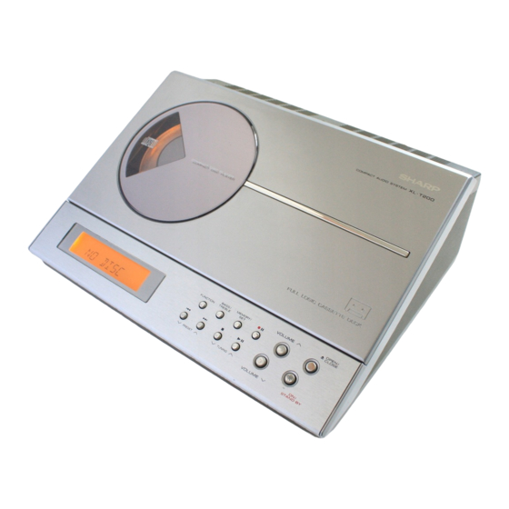
COMPACT AUDIO SYSTEM
XL-T200H
MODEL
XL-T200H Compact Audio System consisting of XL-T200H
(main unit) and CP-XLT200H (speaker system).
• In the interests of user-safety the set should be restored to its original
condition and only parts identical to those specified should be used.
This document has been published to be used
for after sales service only.
The contents are subject to change without notice.
XL-T200H
No. S5235XLT200H/
Page
Advertisement
Table of Contents

Related Manuals for Sharp XL-T200H


Summary of Contents for Sharp XL-T200H
-
Page 1: Table Of Contents
(Except for U.K.) This Service Manual is for the XL-T200H, which is a minor modification model of the XL-T300H. This Service Manual, therefore, describes only the changed points from the Service Manual. Please refer to the XL-T300H Service Manual (S4225XLT300H/) together with this Service Manual. -
Page 2: Safety Precaution For Service Manual
XL-T200H SAFETY PRECAUTION FOR SERVICE MANUAL This product is classified as a CLASS 1 LASER PRODUCT. Precaution to be taken when replacing and servicing the Laser Pickup. The AEL (Accessible Emission Level) of Laser Power Output is less than Class 1 but the laser component is capable of emitting radiation exceeding the limit for Class1. -
Page 3: Specifications
XL-T200H FOR A COMPLETE DESCRIPTION OF THE OPERATION OF THIS UNIT, PLEASE REFER TO THE OPERATION MANUAL. SPECIFICATIONS General Tuner Power source AC 230 V, 50 Hz Frequency range FM: 87.5 - 108 MHz Power on: 26 W AM: 522 - 1,620 kHz... -
Page 4: Names Of Parts
XL-T200H NAMES OF PARTS Front panel 1. CD/Cassette Compartment 2. Function Selector Button 3. Bass/Treble Selector Button 4. Memory/Set Button 5. Tape Record Pause Button 6. Volume Up and Down Buttons 7. CD or Tape Open/Close Button 8. CD Track Down or Fast Reverse, Tape Rewind, Tuner Preset Down Button 9. - Page 5 XL-T200H Remote control 1. Remote Control Transmitter 2. On/Stand-by Button 3. CD Button 4. Tuner and Band Selector Button 5. Timer Button 6. Clock Button 7. Memory Button 8. Dimmer Button 9. Volume Up and Down Buttons 10. Video/Auxiliary Button 11.
-
Page 6: Disassembly
XL-T200H DISASSEMBLY Caution on Disassembly Follow the below-mentioned notes when disassembling the unit and reassembling it, to keep it safe and ensure CD Mechanism excellent performance: Top Cabinet 1. Take compact disc out of the unit. 2. Be sure to remove the power supply plug from the wall Hook outlet before starting to disassemble the unit. - Page 7 XL-T200H (E2) x2 (E1) x1 (E1) x3 ø3 x14mm ø3 x10mm (E1) x3 ø3 x10mm (C1) x1 ø3 x12mm Tuner PWB Main PWB (D1) x1 (C2) x1 ø3 x8mm (D2) x1 (C1) x1 (D1) x1 (F1) x4 ø3 x8mm ø3 x10mm ø2.5 x10mm...
-
Page 8: Removing And Reinstalling The Main Parts
XL-T200H REMOVING AND REINSTALLING THE MAIN PARTS TAPE MECHANISM SECTION (A2)x1 (A2)x1 ø2x7mm ø2x3mm Perform steps 1 and 7 of the disassembly method to remove the tape mechanism. (See page 6,7.) (A1)x2 ø2x8mm How to remove the record / playback and erase heads (See Fig. - Page 9 XL-T200H How to remove the tape mechanism PWB (F1)x1 (F2)x1 (See Fig. 9-1.) ø2x3mm Tape ø2x8mm Mechanism 1. Remove the screws (F1) x 1 pc., to remove the tape Tape mechanism PWB. Mechanism 2. Remove the screws (F2) x 1 pc.
-
Page 10: Notes On Schematic Diagram
XL-T200H NOTES ON SCHEMATIC DIAGRAM • Resistor: • The indicated voltage in each section is the one measured To differentiate the units of resistors, such symbol as K and by Digital Multimeter between such a section and the chas- M are used: the symbol K means 1000 ohm and the symbol sis with no signal given. -
Page 11: Block Diagram
XL-T200H TUNER PWB LOW PASS SWITCHING FILTER AM Band Tracking fL L354 Q351 FM MUTE T302 LEVEL X351 IC521 456kHz VD301 LC72723M SVC348S 15 14 VR351 T306 AM Band Coverage fL Q521 FE301 FM FRONT END BALUN FM IF FM IF... - Page 12 XL-T200H CNP703 CNP301 1 2 3 4 5 6 7 8 R-CH L-OUT IC102 L-CH A–12V SO401 BA3311L VIDEO/AUX INPUT REC./P.B. Q105 Q106 EQUALISER REC MUTE AMP. TAPE MECHANISM ASS'Y SWITCHING RECORD/PLAY Q101-Q104 TERMINAL HEAD CNW101 CNP101 L-CH R-CH ERASE...
- Page 13 XL-T200H FROM FROM TUNER PWB DISPLAY PWB CNP301 CNP702 14 13 12 MAIN PWB O/AUX IC401 RMINAL LC75342M FUNCTION/VOLUME EQUALISER R-CH OUT AUX R TUN R CD R LOGIC CD L TUN L A_12V TAPE L AUX L L-CH OUT...
-
Page 14: Schematic Diagram
XL-T200H AM ANT FM Mute Level Low Pass Fi T302 L354 C329 0.022 VR351 Tracking L353 C360 D301 0.022 1N4148 C335 D302 AM OSC 560P 1N4148 L341 R323 2.3V T306 AM Band BALUN Coverage 2.1V 2.1V FE301 FM FRONT END... - Page 15 XL-T200H R529 AM SIGNAL C527 R528 FM SIGNAL C526 16 15 14 13 12 11 10 (CH) IC521 Low Pass Filter LC72723M L354 C525 4.7V (0V) R361 2.5V 5.6K C537 (CH) C522 C524 0.022 330P 560P R362 5.6K C372 1/50 R366 2.3V...
- Page 16 XL-T200H SWITCH PWB-B2 SW728 PAUSE CD PLAY/ R705 SW727 PAUSE TUNING UP LCD701 R706 FL DISPLAY SW726 MEMORY/ 5.6K R707 CD STOP/ SW725 3.9K CLEAR TUNING DOWN R708 SW724 2.7K BASS/TREBLE R709 SW723 FF>> 2.2K PRESET UP R710 SW722 SW712 1.2K...
- Page 17 XL-T200H MOTOR PWB-A3 DISPLAY PWB-B1 IC804 M801(243-6) TA7291S CD LID CNP902C CD LID MOTOR DRIVER LCD701 FL DISPLAY C840 SWITCH PWB-B3 R845 150K R834 R836 R847 3.3K 1.8K Q807 KRC102 M SW802 CNW902A CD LID Q806 KRC102 M R825 2.2K...
- Page 18 XL-T200H FROM TUNER PWB-C1 CNS301 P15 11-D,E 14 13 12 11 10 9 8 7 6 5 4 3 CNP301 CNP702 FM SIGNAL CD SIGNAL PLAYBACK SIGNAL RECORD SIGNAL TERMINAL PWB-A2 R406 R408 R-CH 2.7K R402 CNW401 L401 AUX R SO401 2.2µH...
- Page 19 XL-T200H FROM PWB-C1 DISPLAY PWB-B1 S301 CNW702 11-D,E P17 12-F 7 6 5 4 3 9 10 11 12 CNP702 MAIN PWB-A1(1/3) R438 6.8K REC R C408 10/16 AUX R R442 TAPE R C406 10/16 TUN R C404 C424 CD R...
- Page 20 XL-T200H MAIN PWB-A1(2/3) CD PICK-UP UNIT (308) HPC-3LX C801 0.022 C802 A_3.3V A3.3V 47/16 C807 100/10 R802 C812 100/10 R803 C806 0.022 R804 3.3V R805 C817 R806 1.6V 1.6V R818 VREF R801 1.1V C818 R821 1.6V 2.3V C815 8.2K 1.6V...
- Page 21 XL-T200H CD SIGNAL CD_STB R848 CD_RES R849 R859 BUCK R841 BUS3 R842 BUS2 R843 BUS1 R844 BUS0 PU_IN GVSW CNP704 A3.3V C817 R818 R855 C818 C835 R821 C824 (CH) 8.2K R816 (CH) R833 R829 5.6K C819 C825 C822 RFGO 100/10...
- Page 22 XL-T200H MAIN PWB-A1(3/3) PLAYBACK SIGNAL RECORD SIGNAL TAPE MECHANISM ASS'Y(212) Q101 Q103 R101 KTC3199 GR KTC3199 GR 1.5V RECORD/PLAY (0V) HEAD C101 C113 CNW101 0.001 4.7/25 L-CH R126 5.6K Q102 0.3V C121 Q104 R140 (8.3V) KTC3199 GR R-CH KTC3199 G 1.5V...
- Page 23 XL-T200H R111 R105 2.2K R115 150K R103 R107 Q101 Q103 R109 R117 C3199 GR KTC3199 GR C129 3.9K 0.7V C109 1.5V C107 0.015 (0V) 47/16 4.7/25 Q105 R131 C111 C115 KTC3199 GR 4.7K 10/16 0.0022 Q102 C105 Q104 TC3199 GR...
-
Page 24: Wiring Side Of P.w.board
XL-T200H TAPE MECHANISM ASS'Y (212) P27 8-G FROM MAIN PWB-A1 CNW901 M901(212-9) RECORD/PLAYBACK TAPE HEAD MOTOR ERASE HEAD 7 6 5 4 3 2 1 SW901 (212-7) SW902 (212-8) FOOL PROOF PH901 PHOTO INTERRUPTER TAPE MECHANISM PWB-E,F SOL901 (212-4) SOLENOID... - Page 25 XL-T200H FROM MAIN TO MAIN PWB-A1 PWB-A1 CNW802 CNP801 P27 10-F CD PICKUP UNIT (308) P27 10-E CD MOTOR PWB-D M702 SLED MOTOR CNP703A CNW801 SW702 PICKUP IN 1 3 5 7 9 11 13 15 2 4 6 8 10 12 14 16...
- Page 26 XL-T200H SO401 VIDEO/AUX IN RIGHT LEFT SO601 SPEAKE TERMINA RIGHT JK601 CHASSIS HEADPHONES JACK SO601 C224 C413 R408 L401 L202 D452 CNP401 D451 C211 TERMINAL PWB-A2 R230 CHAS SO301 ANTENNA TERMINAL FM 75 OHMS R609 R220 R219 CHASSIS R605 CFW301...
- Page 27 XL-T200H When Servicing, Pay attention as the area enclosed SO601 by this line ( ) is directly T682 SPEAKER connected with AC main voltage. POWER TRANSFORMER TERMINAL RIGHT LEFT (MAIN) SO651 AC POWER INPUT SOCKET AC 230V,50Hz SO601 C224 C223...
-
Page 28: Waveforms Of Cd Circuit
XL-T200H WAVEFORMS OF CD CIRCUIT NO DISC FOCUS SEARCH STOP PLAY TMAX IC801 33pin IC801 16pin SBOK IC803 26pin IC801 8pin IC801 41pin IC803 25pin FOCUS SEARCH TOC IL STOP PLAY IC801 38pin IC801 31pin IC801 29pin IC801 34pin IC801 31pin... -
Page 29: Troubleshooting
XL-T200H TROUBLESHOOTING When the CD does not function When the CD section does not operate when the objective lens of the optical pickup is dirty, this section may not operate. Clean the objective lens, and check the playback operation. When this section does not operate even after the above step is taken, check the following items. - Page 30 XL-T200H Make sure that the disc is normal, and set the CD TEST MODE (STEP 1). Is the measured voltage as specified in circuit diagram? Check the main unit power supply circuit. Is "Er-CD01" displayed"? Move the pickup to most internal circumference side of disc.
- Page 31 XL-T200H • Laser failure. Is +6.8V applied to the emitter of Q605 ? Check the PWB pattern between emitter of Q605 and R826. Check the peripheral parts of ZD801,C820 and C821. Is +5V applied to the cathode side of ZD801 ?
- Page 32 XL-T200H • Focus servo sawtooth wave failure. IC801 is faulty. Is sawtooh wave output to the pin 33 (FOO) of IC801 ? 1.5~2.5sec Check the PWB pattern between pin emitter of Q605 and IC803. Is +6.8V applied to the pins 21 and 22 (VCC) of IC803 ?
- Page 33 XL-T200H • HF error. Is output (tracking error signal) obtained at the pins 31 (TEI) Optical pickup failure. Is output obtained at the pins 3 and and 32 (TEZI) of IC801 the CD TEST MODE "STEP 4" is 8 of CNP801/CNW801.
- Page 34 XL-T200H • Track search failure Check as stated in item "SLED MOTOR OPERATION FAILURE". Does the sled motor run in FF/REW state when the SERVO TEST MODE "STEP1" is set? Is the following wave output to the pin 34 (TRO) of IC801 IC801 failure.
- Page 35 XL-T200H PARTS GUIDE COMPACT AUDIO SYSTEM XL-T200H MODEL XL-T200H Compact Audio System consisting of XL-T200H (main unit) and CP-XLT200H (speaker system). “HOW TO ORDER REPLACEMENT PARTS” To have your order filled promptly and correctly, please furnish the For U.S.A. only following information.
- Page 36 XL-T200H PRICE PRICE DESCRIPTION PARTS CODE DESCRIPTION PART CODE RANK RANK LED701~703 VHPSLI343YC-1 AF LED,SLI343YC INTEGRATED CIRCUITS LED801 VHPAUY3335+-1 LED,AUY3335 VD301 VHCSVC348S/-1 AK Variable Capacitance,SVC348S IC101 VHIBA3126N/-1 AF Head Selector,BA3126N ZD351 VHEDZ5R1BSB-1 AC Zener,5.1V,DZ5.1BSB IC102 VHIBA3311L/-1 AK REC./P.B.Equaliser Amp., ZD601...
- Page 37 XL-T200H PRICE PRICE DESCRIPTION PART CODE PARTS CODE DESCRIPTION RANK RANK AB 100 µF,16V,Electrolytic AB 2.2 µF,50V,Electrolytic C155 RC-GZA107AF1C C418 RC-GZA225AF1H AB 0.022 µF,50V AA 0.0027 µF,50V C156 VCKYPA1HF223Z C419,420 VCKYCY1HB272K AB 33 µF,16V,Electrolytic AC 0.1 µF,50V,Mylar C201 RC-EZD336AF1C C421~424 RC-QZA104AFYJ AA 0.0033 µF,50V...
- Page 38 XL-T200H PRICE PRICE DESCRIPTION PART CODE PARTS CODE DESCRIPTION RANK RANK AB 0.022 µF,25V C848,849 VCKYCY1EF223Z R356 VRS-CY1JB102J AA 1 kohm,1/16W AB 47 µF,10V,Electrolytic C850,851 RC-GZA476AF1A R357 VRS-CY1JB474J AA 470 kohms,1/16W C852 VCCCCY1HH150J AA 15 pF (CH),50V R358 VRS-CY1JB822J AA 8.2 kohms,1/16W AC 10 µF,10V,Electrolytic...
- Page 39 XL-T200H PRICE PRICE DESCRIPTION PART CODE PARTS CODE DESCRIPTION RANK RANK R750 VRS-CY1JB102J AA 1 kohm,1/16W R909 VRS-CY1JB183J AA 18 kohms,1/16W R751 VRD-ST2CD102J AA 1 kohm,1/6W R910 VRS-CY1JB333J AA 33 kohms,1/16W R752 VRS-CY1JB102J AA 1 kohm,1/16W R754 VRS-CY1JB102J AA 1 kohm,1/16W...
- Page 40 XL-T200H PRICE PRICE DESCRIPTION PART CODE PARTS CODE DESCRIPTION RANK RANK PCUSG0001AWSA J AD Cushion (Green) XHBSD20P03000 AA Screw,ø2×3mm PCUSG0004AWSA J AD Cushion (Red-Brown) XHBSD20P04000 AA Screw,ø2×4mm 1 308 DCTRH8005SJ01 BA Pickup Unit Ass’y XHBSD20P06500 Screw,ø2×6.5mm XHBSD40P06000 AA Screw,ø4×6mm 308- 1 ————...
- Page 41 XL-T200H 308-3 308-1 308-2 702x2 M701 307x2 M702 306x2 SW702 PWB-D Figure 6 CD MECHANISM EXPLODED VIEW – 6 –...
- Page 42 XL-T200H IC601 613x2 616x2 Q605 Q602 Q603 T682 Silicon Grease Silicon Grease BELT CONNECTION Motor FF/REW Clutch Main 611x2 Belt 616x2 FF/REW 240x4 Flywheel Belt 243-1 243-4 PWB-A1 610x2 243-3 243-5 PWB-B5 243-2 PWB-A2 PWB-A4 233x3 243-6 (M801) PWB-A3 619x2...
- Page 43 XL-T200H Tweeter SP603 (L-CH) SP604 (R-CH) Black 904-1 White Line 904-3 904-2 Black Woofer SP601 (L-CH) SP602 (R-CH) 903-1 904-4 SP603, 604 903-2 903-3 SP601,602 908x4 Tweeter 902x2 SP603 (L-CH) SP604 (R-CH) Woofer SP601 (L-CH) SP602 (R-CH) Figure 8 SPEAKER EXPLODED VIEW...
-
Page 44: Packing Method (For U.k. Only)
23. Sleeve Carton, Speaker SPAKS0006SJZZ Setting position of switches and knobs CD Lid CLOSE © COPYRIGHT 2002 BY SHARP CORPORATION SHARP CORPORATION AV Systems Group ALL RIGHTS RESERVED. Audio Systems Division No part of this publication may be reproduced, Higashihiroshima, Hiroshima 739-0192, Japan...