HP MSM720 Installation Manual
Hide thumbs
Also See for MSM720:
- Specification (27 pages) ,
- Installation manual (25 pages) ,
- Quick start manual (6 pages)
Table of Contents
Advertisement
Quick Links
HP MSM720 Controllers Installation Guide
Abstract
This document describes how to install and initially configure the MSM720 Controllers. This document applies to the MSM720
Access Controller (J9693A) and the MSM720 Premium Mobility Controller (J9694A). These products are hereafter referred to
as controller. See also the MSM7xx Controllers Configuration Guide.
HP Part Number: 5998-3789
Published: October 2013
Edition: 2
Advertisement
Table of Contents

Related Manuals for HP MSM720


Summary of Contents for HP MSM720
- Page 1 HP MSM720 Controllers Installation Guide Abstract This document describes how to install and initially configure the MSM720 Controllers. This document applies to the MSM720 Access Controller (J9693A) and the MSM720 Premium Mobility Controller (J9694A). These products are hereafter referred to as controller.
- Page 2 © Copyright 2013 Hewlett-Packard Development Company, L.P. The information contained herein is subject to change without notice. The only warranties for HP products and services are set forth in the express warranty statements accompanying such products and services. Nothing herein should be construed as constituting an additional warranty. HP shall not be liable for technical or editorial errors or omissions contained herein.
-
Page 3: Table Of Contents
2 Installing the controller................7 Installation procedures.......................8 Installing optional accessories....................15 3 Controller initial configuration..............16 Perform initial configuration......................16 Verify guest access (optional) ....................18 4 Support and other resources..............23 Online documentation......................23 Contacting HP........................23 HP websites...........................23 Typographic conventions......................23 A Specifications..................24 Physical..........................24 Electrical..........................24 Environmental........................24 Acoustic..........................24 Safety...........................24... -
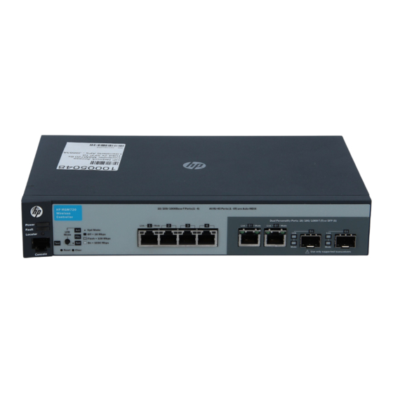
Page 4: Identifying Controller Physical Features
1 Identifying controller physical features Unpacking the controller Unpack your controller and verify that you have received these items: Controller External AC/DC power adapter AC/DC power adapter power cord (for your region) Console port serial cable (DB-9 to RJ-45) Documentation including Safety and Regulatory information Software License, Warranty, and Support information Accessory kit comprised of: ◦... - Page 5 The controller is beginning its boot sequence. Turns on for three seconds at power up or reset. Locator (blue) The Locator LED is used to locate a specific MSM720 in an area full of other controllers and MSM720s. The LED can be set to be on solid or blink for a Blinking specified number of minutes (1- 1 440).
-
Page 6: Resetting To Factory Defaults
One of the following conditions exist: (green) The mini-GBIC is not supported by the current software The mini-GBIC is not a genuine HP Mini-GBIC and is not supported The mini-GBIC is an “A” version in a controller that requires a “B” version or later... -
Page 7: Installing The Controller
For indoor use only. The controller, AC power adapter, and all connected cables are not designed for outdoor use. The HP mini-GBICs are Class 1 laser devices. Avoid direct eye exposure to the beam coming from the transmit port. The rack or cabinet should be adequately secured to prevent it from becoming unstable and/or falling over. -
Page 8: Installation Procedures
CAUTION: Ensure all port covers are installed when the port is not in use. There are no user-serviceable parts inside these products. Any servicing, adjustment, maintenance, or repair must be performed only by service-trained personnel. These products do not have a power switch; they are powered on when the power cord is plugged in. - Page 9 The external AC/DC power adapter automatically adjusts to any voltage between 100-240 volts and either 50 or 60 Hz. The MSM720 cannot be powered by Power over Ethernet (PoE). Check the LEDs on the controller as described below.
- Page 10 LED behavior During the self test: Initially, all the controller and port LEDs are on. Most of the LEDs turn off and then may turn on again during phases of the self test. For the duration of the self test, the Test LED stays on. When the self test completes successfully: The Power LED remains on.
- Page 11 Use a #1 Phillips (cross-head) screwdriver and attach the mounting brackets to the controller with the included 8 mm M4 screws. Figure 5 Attaching mounting brackets WARNING! For safe reliable installation, only use the screws provided in the accessory kit to attach the mounting brackets to the controller.
- Page 12 Attach the controller to the wall or wood surface with two 15.9 mm (5/8 inch) number 12 wood screws (not included). Figure 7 Wall mounting the controller Using on a table For table top use, attach the provided rubber feet to the four underside corners of the controller. To reduce risk of someone tripping on the cables, consider anchoring the cables to a table leg.
- Page 13 You can install or remove an optional mini-GBIC from a mini-GBIC slot without having to power off the controller. Use only HP mini-GBICs. Mini-GBIC information Dual-personality ports use either the 10/100/1000Base-T RJ-45 connector, or a supported HP mini-GBIC (Small Form Factor Pluggable (SFP)) for fiber-optic connection. By default, the RJ-45 connectors are enabled.
- Page 14 CAUTION: Use only supported genuine HP mini-GBICs with your controller. Non-HP mini-GBICs are not supported and their use may result in product malfunction. Contact your HP Networking Sales and Service Office or authorized dealer for additional HP mini-GBICs. NOTE: The mini-GBIC slots are shared with 10/100/1000Base-T RJ-45 ports.
-
Page 15: Installing Optional Accessories
Installing optional accessories Two optional controller accessories are available from HP. HP X510 1U Cable Guard (J9700A): Mounts to the front of the controller to help stabilize and support the networking cables and provide extra security against tampering or theft. -
Page 16: Controller Initial Configuration
On the Login page, enter admin for Username and admin for Password and then select Login. On the HP End User License Agreement page, read the agreement and then select Accept HP End User License Agreement. On the product registration page it is recommended that you register your product now by selecting Register Now. - Page 17 Follow the Configure initial controller settings workflow. It is highly recommended that you follow the Configure initial controller settings workflow. This workflow is selected by default. Select Start to launch this workflow. If you choose not to run a workflow at this time, select the Home button to exit the workflow page. The Configure initial controller settings workflow provides instructions and prompts you for options.
-
Page 18: Verify Guest Access (Optional)
Review the settings before you select Apply to save and activate the new configuration on the controller. Alternatively, select Back to go to the previous workflow page or select Cancel to discard your workflow settings and exit the workflow. After applying your changes, a confirmation page appears showing the menu paths to each configuration page associated with the Configure initial controller settings workflow. - Page 19 Configure basic guest access To configure basic guest access, follow the Create a wireless network for guests workflow. Select Start to launch this workflow. On the Create a new wireless network for guests page, in Wireless network name (SSID) enter Guests, then select Next.
- Page 20 On the Guest DHCP addressing page, select DHCP server. Define the DHCP server IP address range: Set Start address to 192.168.1.1 Set End address to 192.168.1.254 Set Netmask to 255.255.255.0 NOTE: The first address in the range is reserved for the controller gateway and DNS (192.168.1.1 in this example).
- Page 21 Verify the settings and then select Apply. After applying your changes, a confirmation page appears showing the menu paths to each configuration page associated with the Create a wireless network for guests workflow. For example: Select Done. Verify guest access (optional)
- Page 22 Controller port 5T (or any of 6T/5S/6S) must be connected to the Internet for this test to be successful. Open your Web browser and enter the address of an Internet site, for example www.hp.com. The controller intercepts the URL and displays the public access interface Login page.
-
Page 23: Support And Other Resources
4 Support and other resources Online documentation You can download documentation from the HP Support Website at: www.hp.com/support/manuals. Search by product number or name. Contacting HP For worldwide technical support information, see the HP support Website: www.hp.com/ networking/support Before contacting HP, collect the following information:... -
Page 24: A Specifications
A Specifications Physical Width Depth Height Weight 25.4 cm (10 in) 16.5 cm (6.5 in) 4.4 cm (1.73 in) 0.91 kg (2.25 lbs) Electrical AC voltage Maximum current Frequency range 100-240 volts .24A 50/60 Hz Environmental Operating Non-Operating Temperature 5°C to 45°C (41°F to 1 13°F) -40°C to 70°C (-40°F to 158°F) Relative humidity (non-condensing) 15% to 95% at 40°C (104°F) -
Page 25: Ethernet
ESD: IEC 61000-4-2 Radiated: IEC 61000-4-3 EFT/Burst: IEC 61000-4-4 Surge: IEC 61000-4-5 Conducted: IEC 61000-4-6 Power frequency magnetic field: IEC 61000-4-8 Voltage dips and interruptions: IEC 61000-4- 1 1 Harmonics: EN 61000-3-2, IEC 61000-3-2 Flicker: EN 61000-3-3, IEC 61000-3-3 Ethernet Four RJ-45 auto-sensing 10/100/1000 (IEEE 802.3 Type 10Base-T, IEEE 802.3u Type 100Base-TX, IEEE 802.3ab Type 1000Base-T);... -
Page 26: Cabling Specifications
Cabling specifications Twisted-pair 10 Mbps Category 3, 4 or 5, 100-ohm unshielded twisted-pair (UTP) or shielded twisted-pair copper Operation (STP) cable, complying with IEEE 802.3 10BASE-T specifications. 100 Mbps Category 5, 100-ohm UTP or STP cable, complying with IEEE 802.3u 100BASE-TX Operation specifications. - Page 27 Multimode fiber modal Technology Supported cable type bandwidth Supported distances 1000-BX single mode fiber 0.5 - 10,000 meters *For distances less than 20km, a 10dB attenuator must be used. For distances between 20km and 40km, a 5dB attenuator must be used. Attenuators can be purchased from most cable vendors. Cabling distance specifications...
-
Page 28: B Mode Conditioning Patch Cord (Fiber Cables)
Installing the patch cord As shown in the illustration below, connect the patch cord to the HP transceiver with the section of single mode fiber plugged in to the Tx (transmit) port. Then, connect the other end of the patch cord to your network cabling patch panel, or directly to the network multimode fiber. -
Page 29: C Regulatory Information
C Regulatory information FCC Class A Notice Operation is subject to the following two conditions: This equipment has been tested and found to comply with the limits for a Class A digital device, pursuant to Part 15 of the FCC Rules. These limits are designed to provide reasonable protection against interference when the equipment is operated in a commercial environment. -
Page 30: D Recycle Statements
D Recycle statements Waste Electrical and Electronic Equipment (WEEE) statements English recycling notice Disposal of waste equipment by users in private household in the European Union This symbol means do not dispose of your product with your other household waste. Instead, you should protect human health and the environment by handing over your waste equipment to a designated collection point for the recycling of waste electrical and electronic equipment. - Page 31 Estonian recycling notice Äravisatavate seadmete likvideerimine Euroopa Liidu eramajapidamistes See märk näitab, et seadet ei tohi visata olmeprügi hulka. Inimeste tervise ja keskkonna säästmise nimel tuleb äravisatav toode tuua elektriliste ja elektrooniliste seadmete käitlemisega egelevasse kogumispunkti. Küsimuste korral pöörduge kohaliku prügikäitlusettevõtte poole. Finnish recycling notice Kotitalousjätteiden hävittäminen Euroopan unionin alueella Tämä...
- Page 32 Italian recycling notice Smaltimento di apparecchiature usate da parte di utenti privati nell'Unione Europea Questo simbolo avvisa di non smaltire il prodotto con i normali rifi uti domestici. Rispettare la salute umana e l'ambiente conferendo l'apparecchiatura dismessa a un centro di raccolta designato per il riciclo di apparecchiature elettroniche ed elettriche.
- Page 33 Romanian recycling notice Casarea echipamentului uzat de către utilizatorii casnici din Uniunea Europeană Acest simbol înseamnă să nu se arunce produsul cu alte deşeuri menajere. În schimb, trebuie să protejaţi sănătatea umană şi mediul predând echipamentul uzat la un punct de colectare desemnat pentru reciclarea echipamentelor electrice şi electronice uzate.