Table of Contents

Summary of Contents for ABB ACSM1-204
- Page 1 ACSM1 Quick Installation and Start-up Guide ACSM1-204 Regen Supply Module English ....Appendix... . . 3AUA0000060576 REV A Effective: 2009-10-05 ©...
-
Page 2: List Of Related Manuals In English
List of related manuals in English REGEN SUPPLY MODULE MANUALS Code (EN) ACSM1-204 Regen Supply Modules Hardware Manual 3AUA0000053713 ACSM1-204 Regen Supply Modules Firmware Manual 3AUA0000052174 ACSM1-204 Quick Installation and Start-up Guide 3AUA0000060576 WFU-xx Regen Filter Module Quick Installation Guide... -
Page 3: About This Guide
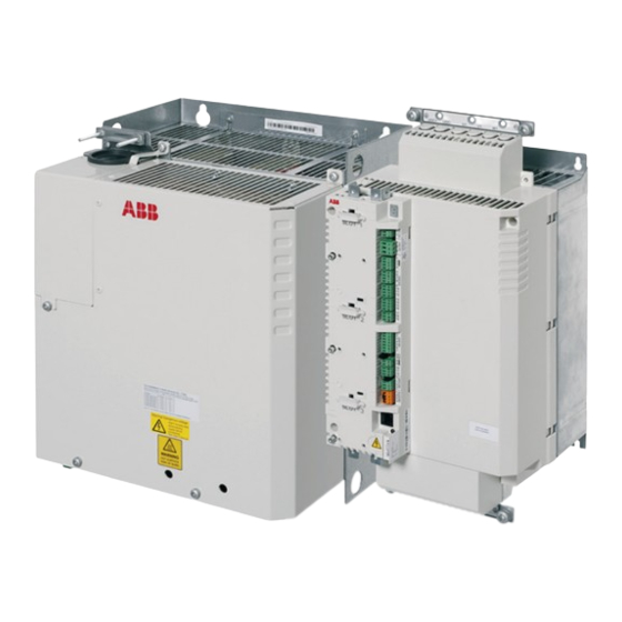
ACSM1-04 drive module(s) AC motor Applicability This manual applies to the ACSM1-204 regen supply module (frame sizes A to D). For instructions on installing the regen filter module, see WFU-xx Regen Filter Module Installation Guide and ACSM1-204 Regen Supply Modules Hardware Manual. -
Page 4: Related Documents
Planning the installation • The ACSM1-204 is an IP20 (UL open type) regen supply module to be used in a heated, indoor controlled environment. The regen supply module must be installed in clean air according to enclosure classification. Cooling air must be clean, free from corrosive materials and electrically conductive dust. -
Page 5: Mechanical Installation
Quick installation and start-up guide – ACSM1-204 5 Mechanical installation Fasten the regen supply module to the mounting base using screws through the four mounting holes. Frame A and B can be mounted onto a DIN rail, but it is recommended to fasten the modules to the mounting base also by two screws through the lower mounting holes. - Page 6 6 Quick installation and start-up guide – ACSM1-204 labeled VARISTOR (1 screw) and FILTER (2 screws) in the regen filter module (under the cover). • Fasten the two cable clamp plates included with the regen supply module, one at the top, one at the bottom. The clamp plates are identical.
-
Page 7: Cabling Examples
Quick installation and start-up guide – ACSM1-204 7 Cabling examples Frame size A Frame size B UDC+UDC- Frame sizes C and D Cable clamp on bare shield. Bare shield. Cover with insulating tape. Screw lug detail: UDC+ U1 V1 W1... -
Page 8: Installing The Control Cables
8 Quick installation and start-up guide – ACSM1-204 Recommended wire sizes Filter unit mains supply cable Regen supply module Wire size Wire size (AWG) frame size 1.5 … 4 mm 15 … 12 2.5 … 6 mm 13 … 10 10 …... -
Page 9: Default I/O Connection Diagram
Quick installation and start-up guide – ACSM1-204 9 Default I/O connection diagram External power input +24VI Notes: 24 V DC, 1.6 A *Total maximum current: 200 Wire sizes and tightening Relay output torques: 250 V AC / 30 V DC X2: 0.5 …... -
Page 10: Default Connections
10 Quick installation and start-up guide – ACSM1-204 Default connections Make the following connections on the control unit before attempting to start up the regen supply module: • X3:14, 15 Fan control signal. The fan control cable must be connected. - Page 11 Quick installation and start-up guide – ACSM1-204 11 Start-up Safety The start-up may only be carried out by a qualified electrician. The safety instructions must be followed during the start-up procedure. See the safety instructions on the first pages of the appropriate hardware manual.
- Page 12 12 Quick installation and start-up guide – ACSM1-204...
- Page 13 Appendix 13 Appendix Installation example: power and control connections WFU-xx ACSM1-204 ACSM1-04 UDC+/UDC-/PE L1/L2/L3/PE DIO1 (X3: 14, 15) TH (X4: 8, 9) U2/V2/W2/PE 24 V DC...
- Page 14 14 Appendix...


