Kenwood NX-5000 Series Manual
Hide thumbs
Also See for NX-5000 Series:
- User manual ,
- Common function reference (476 pages) ,
- Function reference (190 pages)

Related Manuals for Kenwood NX-5000 Series


Summary of Contents for Kenwood NX-5000 Series
- Page 1 NX-5000 series P25 Function Reference (P25 FUNC) Version: 2.20 Last Updated: May 31, 2017 Language: English Type: © 2017...
- Page 2 CONTENTS CONTENTS CONTENTS About this Manual P25 CONVENTIONAL SYSTEM How to Read the In-depth Manual viii Initiating Voice Communications (Basic About Notations viii Transmission and Reception) About the Notation of the Supported About Own ID Models About Communication Security About Examples of the Transceiver (Encryption) Display...
- Page 3 CONTENTS Making an Individual Call 1.10 Receiving GPS Data Initiating an Individual Call GPS Position Display Receiving an Individual Call 1.11 Disabling the Transceiver Capability by Remote Control (Radio Inhibit / Uninhibit) Individual ID List Transceiver Behavior upon Receipt of Restricting IDs for Which the Transceiver Can the Radio Inhibit Request Command Initiate a Call (Individual ID Encode Block)
- Page 4 CONTENTS Using P25 ID to Initiate a Selective Call P25 TRUNKING SYSTEM Available Calls Initiating Voice Communications (Basic Making an Individual Call Transmission and Reception) Initiating an Individual Call About Own ID Receiving an Individual Call Control Channel Acquisition and Individual ID List Registration Making a Group Call...
- Page 5 CONTENTS 2.15 Making the Transceiver Migrate to a COMMUNICATIONS IN AN Particular Talkgroup (Dynamic EMERGENCY Regrouping) Configuring the Dynamic Regrouping Placing the Transceiver in Emergency Mode Functions of Dynamic Regrouping Emergency Alarm 2.16 Notifying the System of the Transceiver Status (Status) Emergency Talkgroup (P25 Trunking System Only)
- Page 6 CONTENTS COMMUNICATION SECURITY P25 OTAR Toggling the Encryption during About the Encryption Key Transmission between Enabled and Configurations for the Transceiver Disabled Required for Using OTAR Configuring the Encryption Key Data Used CAI Data Packet Communication for Communications (P25 Conventional CAI Data Registration (P25 Conventional System Only) System Only)
- Page 7 CONTENTS Scan Function SCAN Adding or Deleting a Channel to/from the Starting the Scan Target Channels for Scan (Scan Delete/ Add) Scanning in One Zone (Single Scan) Adding or Deleting a Zone to or from the Conditions to Activate the Scan (Single Target Zones for Scanning (Zone Delete/ Scan) Add)
- Page 8 About this Manual About this Manual This manual describes the functions of the NX-5200/ NX-5300/ NX-5400/ NX-5700/ NX-5800/ NX-5900 transceiver operated in the P25 system. This document is created for the product having the following design specifications: Item Specifications How to Verify Market Code K, F...
- Page 9 How to Read the In-depth Manual How to Read the In-depth Manual The In-depth Manual has the following sections: Common Function Reference (Common FUNC) Describes the functions common to the transceivers. Analog Function Reference (Analog FUNC) Describes the analog functions of the transceiver. P25 Function Reference (P25 FUNC) Describes the P25 functions of the transceiver.
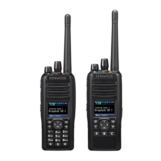
- Page 10 About Notations About the Notation of the Supported Models This manual describes the supported models according to the following rules: Model Name Notation NX-5200 NX-5300 Portable NX-5400 700 MHz/ 800 MHz NX-5700 NX-5800 Mobile NX-5900 700 MHz/ 800 MHz About Examples of the Transceiver Display This manual describes mainly by using the display examples of Portable display if the functions are common to the transceivers.
- Page 11 Abbreviations Used in this Document Abbreviation Full Spelling or Meaning Field Programming Unit Global Positioning System H-CPM Harmonized Continuous Phase Modulation H-DQPSK Harmonized Differential Quadrature Phase Shift Keying Header Data Unit Identification Key Encryption Key Key Management Facility Key Management Message Key Variable Loader LRRP Location Request/Response Protocol...
- Page 12 Bluetooth SIG, Inc., and any use of such marks by JVC KENWOOD Corporation is under license. All other trademarks and trade names are the trademarks and trade names of their respective owners.
- Page 13 About the Programming Software About the Programming Software Various functions and parameters of the transceiver can be configured by using the KPG-D1/ D1N software. Various functions can be enabled by connecting the transceiver to a PC by use of the KPG-36U/ KPG-36X (Portable) or KPG-46U/ KPG-46X (Mobile) programming cable and writing the data configured using KPG-D1/ D1N to the transceiver.
- Page 14 Multi RF Deck/ Multi Control Head, and for the special functions of Multi RF Deck/ Multi Control Head. About Options to Use the Functions Described in This Document To use the functions described in this document, the following KENWOOD optional accessories need to be prepared on your own as necessary: Portable/ Mobile...
- Page 15 About the Built-in GPS Receiver Unit About the Built-in GPS Receiver Unit The GPS receiver is built-in for NX-5200/ NX-5300/ NX-5400/ NX-5700/ NX-5800/ NX-5900. Read the following warnings before using the built-in GPS receiver unit of NX-5200/ NX-5300/ NX-5400/ NX-5700/ NX-5800/ NX-5900. On the use of the GPS With frequency interference in the GPS receive frequency range to the transceiver or another transceiver, the GPS receiver may not position normally.
- Page 16 How to Search for Information INDEX Clicking a function name, a title or a page number in the Index pages allows a jump to the corresponding page. Blue characters in the main text Clicking a portion with blue characters in the main context allows a jump to the corresponding page. Blue characters at the bottom of each page Clicking a portion with blue characters located at the bottom of each page allows a jump to the first page of the contents or index.
- Page 17 Revision History Revision History Date Description 1) Added NX-5900 (700 MHz/ 800 MHz model) as a supported model. 2) Added the information of KCH-20R (Featured Panel) as a supported Control Head. 3) Added KPG-36X and KPG-46X as supported programming cables. 4) Changed the description in “About this Manual”...
- Page 18 Revision History Date Description 37) Added the notes to “5.3 CAI Data Packet Communication”. 38) Corrected the information of “Data Packet Communication During a Scan (P25 Conventional System Only)” and moved “Data Packet Communication During a Scan (P25 Conventional System Only)” to “6.8 Scan Function”.
- Page 19 Revision History Date Description 1) Changed the version information in “About This Manual”. 2) Added description on Optional Signaling LED in Table 1-1. 3) Added “Optional Signaling LED” to “1.1 Initiating Voice Communications (Basic Transmission and Reception)”. 4) Added description on Optional Signaling LED in “Initiating an Individual Call” and “Receiving an Individual Call”...
- Page 20 CONTENTS BY PURPOSE Making an Individual Call Making a Group Call Functions for A user can call an individual transceiver and A voice call can be established by calling a group Conventional initiate voice communication. of transceivers registered as a call group. System Making an Individual Call Making a Group Call...
- Page 21 1 P25 CONVENTIONAL SYSTEM P25 CONVENTIONAL SYSTEM P25 is a generic name for a digital communication system protocol which complies with the APCO Project25 Standard specified in TIA-102. Using P25, the transceiver can make an individual call or group call for voice calls, communicate various types of messages, or send and receive GPS data.
- Page 22 1 P25 CONVENTIONAL SYSTEM 1.1 Initiating Voice Communications (Basic Transmission and Reception) Initiating Voice Communications (Basic Transmission and Reception) This section describes the basic methods for transmission and reception in a P25 Conventional system and the relevant functions. About Own ID To initiate various communications using P25, a Unit ID (Own), the identification code of a transceiver, needs to be configured for the transceiver.
- Page 23 1 P25 CONVENTIONAL SYSTEM 1.1 Initiating Voice Communications (Basic Transmission and Reception) Auto Reset Timer Auto Reset Timer is the time until the status of the LCD display, flashing LED and sounding Alert Tone is automatically reset when communication is established by the transmission or reception of a voice call. By using KPG-D1/ D1N, Auto Reset Timer can be configured.
- Page 24 1 P25 CONVENTIONAL SYSTEM 1.1 Initiating Voice Communications (Basic Transmission and Reception) Configuration using KPG-D1/ D1N Configuring Selective Call Alert LED ( Transceiver Settings > P25 > P25 Information > Conventional) Configuring Alert LED Color ( Transceiver Settings > P25 > P25 Information > Conventional > Alert LED Color) Configuring Alert LED Color (Individual ID List) ( Transceiver Settings >...
- Page 25 1 P25 CONVENTIONAL SYSTEM 1.1 Initiating Voice Communications (Basic Transmission and Reception) Configuration using KPG-D1/ D1N Configuring Late Entry Fast Unmute (Personality) to be enabled or disabled ( Transceiver Settings > Personal > Personality > P25 Conventional (P25 Voting with NAC) > P25) Configuring Late Entry Fast Unmute (Channel Edit) to be enabled or disabled ( Transceiver Settings >...
- Page 26 1 P25 CONVENTIONAL SYSTEM 1.1 Initiating Voice Communications (Basic Transmission and Reception) Note If “Off” is configured for TOT Pre-alert, no TOT Pre-alert tone will sound from the transceiver. TOT Rekey Time TOT Rekey Time is the amount of time from when the transceiver stops the transmission by the Time-out Timer until transmission becomes possible again.
- Page 27 1 P25 CONVENTIONAL SYSTEM 1.1 Initiating Voice Communications (Basic Transmission and Reception) Configuration using KPG-D1/ D1N Configuring Time-out Timer ( Transceiver Settings > Personal > Personal Features > P25 Conventional (P25 Voting with NAC) > General > Time-out Timer) Configuring TOT Pre-alert ( Transceiver Settings >...
- Page 28 1 P25 CONVENTIONAL SYSTEM 1.1 Initiating Voice Communications (Basic Transmission and Reception) Note Busy Channel Lockout does not function in Emergency Mode. Configuration using KPG-D1/ D1N Configuring Busy Channel Lockout (Personality) ( Transceiver Settings > Personal > Personality > P25 Conventional (P25 Voting with NAC) >...
- Page 29 1 P25 CONVENTIONAL SYSTEM 1.1 Initiating Voice Communications (Basic Transmission and Reception) Communicating Without Using a Repeater (Talk Around) Talk Around is the function that allows transceivers to communicate directly without using a repeater. If the transceiver cannot link to a repeater due to too great distance between the transceiver and the repeater, the transceiver can directly communicate with the target transceiver by using Talk Around.
- Page 30 1 P25 CONVENTIONAL SYSTEM 1.1 Initiating Voice Communications (Basic Transmission and Reception) Configuration using KPG-D1/ D1N Assigning functions to the PF keys on the transceiver ( Transceiver Settings > Key Assignment) Configuring Talk Around to be enabled or disabled (Personality) ( Transceiver Settings >...
- Page 31 1 P25 CONVENTIONAL SYSTEM 1.2 Using the Signaling Using the Signaling NAC is the signaling to be used for facilitating communication within a group if the same channel is shared by several groups. Sharing the Same Channel (Frequency) by Several Groups (NAC) NAC (Network Access Code) is a digital signaling type having the same function as analog QT tone or DQT code.
- Page 32 1 P25 CONVENTIONAL SYSTEM 1.2 Using the Signaling Using the Optional Signaling (P25) Optional Signaling is the signaling used to initiate a selective call. The Optional Signaling available for a P25 Conventional system is 2-tone. (Refer to Using 2-tone to Initiate an Individual Call.) 2-tone signaling uses a pair of 2 different tone frequencies in series for an individual call.
- Page 33 1 P25 CONVENTIONAL SYSTEM 1.2 Using the Signaling The transceiver behaves as follows according to the type of a received signal on a channel with “Mixed” configured in Channel Type. If the transceiver receives analog signals The transceiver behaves according to the configuration in Audio Control (Analog). If the transceiver receives digital signals The transceiver behaves according to the configuration in Audio Control (P25).
- Page 34 1 P25 CONVENTIONAL SYSTEM 1.2 Using the Signaling Squelch Off Momentary key Press and hold the Squelch Off Momentary key. The “Z” icon appears. For the channel where NAC Decode is configured, the transceiver unmutes the speaker just by disabling the NAC and detecting a frame.
- Page 35 1 P25 CONVENTIONAL SYSTEM 1.2 Using the Signaling Operating the transceiver Monitor key Press the Monitor key while Monitor is disabled. The “Z” icon appears. For the channel where NAC Decode is configured, the transceiver unmutes the speaker just by disabling the NAC and detecting a frame.
- Page 36 1 P25 CONVENTIONAL SYSTEM 1.2 Using the Signaling Configuration using KPG-D1/ D1N Configuring Off-hook Decode to be enabled or disabled ( Transceiver Settings > Optional Features >Optional Features 1 > Microphone-hook) Waiting for Both Digital Signals and Analog Signals (Mixed Mode) Mixed Mode is the function to wait for both digital signals and analog signals.
- Page 37 1 P25 CONVENTIONAL SYSTEM 1.3 Waiting for Both Digital Signals and Analog Signals (Mixed Mode) The following is the difference in operation for transmission depending on the transceiver configuration and the received signal. Table 1-6 Mixed Mode Optional Received Transmit Mode Transmission Operation Signaling signal...
- Page 38 1 P25 CONVENTIONAL SYSTEM 1.4 Using P25 ID to Initiate a Selective Call Using P25 ID to Initiate a Selective Call An individual call and group call are available by using P25 IDs. Available Calls The following various types of calls can be used in a P25 Conventional system. For transceiver operations and behaviors, refer to the instructions of each call type.
- Page 39 1 P25 CONVENTIONAL SYSTEM 1.5 Making an Individual Call Making an Individual Call Individual Call is the function used to initiate a call to a target transceiver individually to establish voice calls. By specifying an Individual ID, the transceiver can initiate a call to the transceiver having the Individual ID. Initiating an Individual Call An Individual Call can be started by one of the following methods: Individual Call Mode...
- Page 40 1 P25 CONVENTIONAL SYSTEM 1.5 Making an Individual Call Press the key to select an Individual ID from the Individual ID List. Refer to Common FUNC “Selecting or Clearing Data from a List” for 12 : 34 selection methods. Individual TRUCK 824 TRUCK 825 TRUCK 826...
- Page 41 1 P25 CONVENTIONAL SYSTEM 1.5 Making an Individual Call Enter an Individual ID. Refer to Common FUNC “Entering or Deleting a Code” for the entry 12 : 34 method. Individual If using the PF keys: A character can be selected by pressing the [G] key or the [H] key, and pressing the Menu ([Q]) key can confirm the selected character.
- Page 42 1 P25 CONVENTIONAL SYSTEM 1.5 Making an Individual Call Receiving an Individual Call If the received Individual ID matches the Individual ID configured for the transceiver, the transceiver can receive the Individual Call. To receive an Individual Call in a P25 Conventional system, the transceiver needs to wait on a channel with “Selective Call” configured in Squelch Type.
- Page 43 1 P25 CONVENTIONAL SYSTEM 1.5 Making an Individual Call About the behavior of the transceiver when receiving an Individual Call (P25 Conventional) Alert Tone If the received Individual ID is configured in the Individual ID List, an Alert Tone sounds from the transceiver according to the configuration in Alert Tone (Individual) of the corresponding Individual ID.
- Page 44 1 P25 CONVENTIONAL SYSTEM 1.5 Making an Individual Call Individual ID List If making Individual Calls, the desired Individual IDs need to be preconfigured in the transceiver using KPG-D1/ D1N prior to use of the transceiver. A maximum of 1500 Individual IDs can be configured for Individual ID List. A user can store a maximum of 32 Individual IDs in the Individual ID List.
- Page 45 1 P25 CONVENTIONAL SYSTEM 1.5 Making an Individual Call Configuration Description When using the OTAR function, whether to use the KMF Profile can be configured. (Refer to KMF Profile OTAR.) When using the OTAR function, the profile number of a KMF which will communicate with the KMF Profile Number transceiver can be configured.
- Page 46 1 P25 CONVENTIONAL SYSTEM 1.6 Making a Group Call Operating the transceiver Making a Group Call Select a channel where a Talkgroup ID is configured. 12 : 34 Z o n e 1 C h a n n e l 1 Menu Zone+ Press the...
- Page 47 1 P25 CONVENTIONAL SYSTEM 1.6 Making a Group Call Note In the following cases, the transceiver cannot be placed in Talkgroup ID Select Mode: If an analog channel is selected If no Talkgroup ID is configured for the selected channel If Talkgroup Strapped is enabled (Refer to Prohibiting Change to the Talkgroup ID (Talkgroup Strapped).)
- Page 48 1 P25 CONVENTIONAL SYSTEM 1.6 Making a Group Call About the behavior of the transceiver when receiving a Group Call (P25 Conventional) Alert Tone If the received Talkgroup ID is configured in the Talkgroup ID List, an Alert Tone sounds from the transceiver according to the configuration for Alert Tone (Talkgroup ID List) of the corresponding Talkgroup ID.
- Page 49 1 P25 CONVENTIONAL SYSTEM 1.6 Making a Group Call Talkgroup ID List When making a Group Call, the transceiver communicates using a Talkgroup ID registered in the Talkgroup ID List. By using KPG-D1/ D1N, a target Talkgroup ID needs to be preconfigured for the transceiver as the Talkgroup ID List. A maximum of 1,500 Talkgroup IDs can be configured in the Talkgroup ID List.
- Page 50 1 P25 CONVENTIONAL SYSTEM 1.6 Making a Group Call Configuration Description How Encryption is used when the transceiver transmits on a P25 digital channel can be configured. (Refer to COMMUNICATION SECURITY.) Clear: The transceiver always sends communication data without encrypting the data. Even if Encryption is enabled by operating the transceiver, the transceiver sends communication data without encryption.
- Page 51 1 P25 CONVENTIONAL SYSTEM 1.6 Making a Group Call Configuration using KPG-D1/ D1N Configuring Unit ID Display on Group Call ( Transceiver Settings > P25 > P25 Information > General) Using 2-tone to Initiate an Individual Call 2-tone signaling uses a pair of 2 different tone frequencies in series for an individual call. 2-tone is a signaling system that can receive a signal with squelch disabled only when 2 tone signals in series sent from the transmitting transceiver match the tone signals preconfigured for the receiving transceiver.
- Page 52 1 P25 CONVENTIONAL SYSTEM 1.7 Using 2-tone to Initiate an Individual Call Press the key or key and select the 2-tone code. Refer to Common FUNC “Selecting or Clearing Data from a List” for 12 : 34 selection methods. 2-tone 2-tone 1 Note 2-tone 2...
- Page 53 1 P25 CONVENTIONAL SYSTEM 1.7 Using 2-tone to Initiate an Individual Call Functions Related to 2-tone Code Encoding Functions related to 2-tone code encoding are shown below. Duration of 1st Tone Duration of 2nd Tone Duration of Single Tone Gap Time First Tone Delay Time Sidetone 2-tone Encoding List...
- Page 54 1 P25 CONVENTIONAL SYSTEM 1.7 Using 2-tone to Initiate an Individual Call 2-tone Encode Duration of 1st Tone Duration of 2nd Tone 1st Tone 2nd Tone First Tone Delay Time Gap Time Single Tone Encode Duration of Single Tone Single Tone First Tone Delay Time Figure 1-6 Duration of Single Tone/ Gap Time/ First Tone Delay Time Sidetone...
- Page 55 1 P25 CONVENTIONAL SYSTEM 1.7 Using 2-tone to Initiate an Individual Call Decoding the 2-tone Code The transceiver can wait for a 2-tone code on a channel with “2-tone 1”, “2-tone 2”, “2-tone 3”, or “2-tone 4” configured in Optional Signaling (P25). (Refer to Using the Optional Signaling (P25).) Transceiver behavior...
- Page 56 1 P25 CONVENTIONAL SYSTEM 1.7 Using 2-tone to Initiate an Individual Call Call Format Call Format is the combination of A Tone, B Tone, C Tone, and D Tone the transceiver waits to receive. The following combinations are available. Table 1-10 List of Call Format Combinations Combination Description A and B...
- Page 57 1 P25 CONVENTIONAL SYSTEM 1.7 Using 2-tone to Initiate an Individual Call Alert LED Color When the 2-tone code matches, the LED flashes according the configuration in Alert LED Color. Table 1-12 Alert LED Color Configuration Description The LED does not flash. The LED flashes red.
- Page 58 1 P25 CONVENTIONAL SYSTEM 1.7 Using 2-tone to Initiate an Individual Call Auto Reset Timer Auto Reset Timer is the length of time from when the received 2-tone code matches the 2-tone code preconfigured for the transceiver until the matching state is automatically reset. Auto Reset Timer is configured using KPG-D1/ D1N.
- Page 59 1 P25 CONVENTIONAL SYSTEM 1.7 Using 2-tone to Initiate an Individual Call Table 1-14 Conditions to Reset the 2-tone Code Conditions Description When the following keys are pressed Channel Up key Channel Recall key Channel Down key Clear key Direct Channel 1 to Direct Channel 5 keys Direct Channel 1 Select to Direct Channel 5 Select keys Emergency key Home Channel key...
- Page 60 1 P25 CONVENTIONAL SYSTEM 1.8 Using the Tactical Zone Using the Tactical Zone Tactical Zone is the function to create a new group by registering an arbitrary channel in the Tactical Zone after selecting the channel from the P25 Conventional system channels configured for the transceiver. This function is used when the channels registered in each zone are operated in a single zone.
- Page 61 1 P25 CONVENTIONAL SYSTEM 1.8 Using the Tactical Zone Registering channels of a zone collectively in the Tactical Zone Select a zone other than the Tactical Zone. 12 : 34 Zone 1 Channel 1 Menu Zone+ Press and hold the Tactical Zone key.
- Page 62 1 P25 CONVENTIONAL SYSTEM 1.8 Using the Tactical Zone Migrating to the Tactical Zone A Tactical Zone is treated as Zone 0. Zone 0 is the zone number between the highest zone number and the lowest zone number of the zones registered by using KPG-D1/ D1N. Zone 0 (the Tactical Zone) is selected by operating the Zone Up/ Zone Down key or the Selector.
- Page 63 1 P25 CONVENTIONAL SYSTEM 1.8 Using the Tactical Zone Note If “End Stop” is configured in Rollover/End Stop, pressing the Zone Up key while the zone having the highest number is selected causes the transceiver to migrate to Zone 0 (the Tactical Zone), but pressing the Zone Down key while the zone having the lowest number is selected cannot cause the transceiver to migrate to Zone 0.
- Page 64 1 P25 CONVENTIONAL SYSTEM 1.8 Using the Tactical Zone Deregistering the Tactical Zone The registration status of a channel registered in the Tactical Zone can be deregistered. Operating the transceiver Deregistering the selected channel from the Tactical Zone Select a channel to be deregistered in Zone 0 (the Tactical Zone). 12 : 34 Zone 1 Channel 2...
- Page 65 1 P25 CONVENTIONAL SYSTEM 1.9 Sending GPS Data Sending GPS Data Global Positioning System (GPS) is the system to acquire the current location information of the own transceiver by receiving signals from the Global Positioning System satellites orbiting the earth. The transceiver of the mobile station can send the acquired own location information (GPS data) to the base station.
- Page 66 1 P25 CONVENTIONAL SYSTEM 1.9 Sending GPS Data The ID of the Target Transceiver (GPS Target ID) GPS Target ID is the ID of the target transceiver used for sending GPS data. By using KPG-D1/ D1N, a Target ID can be configured in the range between 000001 and FFFFFF (hexadecimal), or between 1 and 16777215 (decimal).
- Page 67 1 P25 CONVENTIONAL SYSTEM 1.9 Sending GPS Data When a channel not configured for the transceiver is selected While the transceiver is in the TX Unlock state While the transceiver is in busy state While the transceiver is transmitting While the transceiver unmutes the speaker When the Public Address function is used (Mobile only) (Refer to Common FUNC Using the Transceiver as a Megaphone (Public...
- Page 68 1 P25 CONVENTIONAL SYSTEM 1.9 Sending GPS Data If the timing of GPS data transmission by Power-on comes while the transceiver is in busy state The transceiver starts checking the busy state for the GPS data transmission. During this time, “Send Data” appears on the transceiver display.
- Page 69 1 P25 CONVENTIONAL SYSTEM 1.9 Sending GPS Data Sending GPS Data in Emergency Mode (GPS Report) If the transceiver enters Emergency Mode or if Emergency Alarm is enabled, GPS data can be sent when the transceiver enters Emergency Mode after the Emergency Alarm behavior completes. (Refer to COMMUNICATIONS IN AN EMERGENCY.) Also, GPS data can be sent at the following timings while the transceiver is in Emergency Mode:...
- Page 70 1 P25 CONVENTIONAL SYSTEM 1.9 Sending GPS Data GPS Report Interval Time GPS Report Interval Time is the function to send GPS data at regular intervals if Auto GPS Report is enabled. GPS Report Interval Time (Portable/Ignition On) GPS Report Interval (Portable/Ignition On) is the interval to send GPS data while the Ignition Sense port goes high level. In order to automatically transmit GPS data for Portable, this configuration is used.
- Page 71 1 P25 CONVENTIONAL SYSTEM 1.10 Receiving GPS Data 1.10 Receiving GPS Data The base station receiving GPS data from the transceiver of a mobile station can send the GPS data to a PC as serial commands. If a PC installed with a mapping application is connected to the communication port of the base station transceiver, the location information of mobile station transceivers appears on a map on the PC display.
- Page 72 1 P25 CONVENTIONAL SYSTEM 1.11 Disabling the Transceiver Capability by Remote Control (Radio Inhibit / Uninhibit) Note The transceiver enters the Radio Inhibit state when the transceiver receives a Radio Inhibit request message even if the transceiver receives DTMF or FleetSync signaling and enters the Stun state. If the transceiver in this state receives a command to reset the Stun state, the Stun state is reset, but the Radio Inhibit state is not reset.
- Page 73 1 P25 CONVENTIONAL SYSTEM 1.11 Disabling the Transceiver Capability by Remote Control (Radio Inhibit / Uninhibit) The following are the modes that function while the transceiver is placed in the Radio Inhibit state: FPU Programming Mode (only Read is available) Transceiver Information Mode PC Test Mode PC Tuning Mode...
- Page 74 1 P25 CONVENTIONAL SYSTEM 1.12 Actions for Other Transceivers However, the following are the cases that the transceiver does not send an ACK nor initiate an Individual Call: If the Target ID for a Remote Monitor request message is configured for other than own If the transceiver receives a Radio Monitor request message while the transceiver is in the Radio Inhibit state If the transceiver receives a Radio Monitor request message on a channel where no transmit frequency is configured and only reception is available...
- Page 75 1 P25 CONVENTIONAL SYSTEM 1.13 Migrating Automatically to the Site Providing Better Radio Environment (P25 Voting) 1.13 Migrating Automatically to the Site Providing Better Radio Environment (P25 Voting) P25 Voting is the function to migrate automatically to the site (channel) providing better radio environment if the transceiver is operated in a P25 Conventional system.
- Page 76 1 P25 CONVENTIONAL SYSTEM 1.13 Migrating Automatically to the Site Providing Better Radio Environment (P25 Voting) The behavior if “Channel Table” is configured in Zone-channel Format If a zone in a system with “P25 Voting with NAC” configured is selected, P25 Voting is initiated for the channels configured in the zone.
- Page 77 1 P25 CONVENTIONAL SYSTEM 1.13 Migrating Automatically to the Site Providing Better Radio Environment (P25 Voting) Note The configurations by using KPG-D1/ D1N are restricted as follows according to the configuration for Zone-channel Format (Personality or Channel Table). Personality: 2 or more and a maximum of 512 Personalities can be configured for a system with “P25 Voting with NAC” configured. The following functions cannot be configured for a channel with “P25 Voting with NAC”...
- Page 78 1 P25 CONVENTIONAL SYSTEM 1.13 Migrating Automatically to the Site Providing Better Radio Environment (P25 Voting) Voting Link Delay Time The length of time until the repeater in each site is activated may vary depending on the site. Voting Link Delay Time is the function to configure the length of time to tolerate, by delaying the time to start searching for the Frame Sync on other channels, a variation in time of when each repeater is activated.
- Page 79 1 P25 CONVENTIONAL SYSTEM 1.13 Migrating Automatically to the Site Providing Better Radio Environment (P25 Voting) Quick Vote Level Quick Vote Level is the function to allow Voting to behave faster when the transceiver is in an area with a strong signal. If the transceiver receives a signal with a level higher than the value configured in Quick Vote Level during Voting, the channel becomes the Revert Channel.
- Page 80 1 P25 CONVENTIONAL SYSTEM 1.13 Migrating Automatically to the Site Providing Better Radio Environment (P25 Voting) Off-hook Voting Supported Models: Mobile Off-hook Voting is the function to initiate Voting depending on the status of microphone, either on-hook or off-hook. The transceiver behaves as follows according to the configuration in Off-hook Voting: Table 1-17 Off-hook Voting Configuration Description...
- Page 81 1 P25 CONVENTIONAL SYSTEM 1.14 Sending and Receiving a Text Message (Text Messaging) 1.14 Sending and Receiving a Text Message (Text Messaging) Text Messaging is the message communication function to send and receive a maximum of 200-byte text string. The information which is difficult to send by voice, such as an address or a telephone number, can be sent by using text.
- Page 82 1 P25 CONVENTIONAL SYSTEM 1.14 Sending and Receiving a Text Message (Text Messaging) Press the key to select an Individual ID from the Individual ID List. Refer to Common FUNC “Selecting or Clearing Data from a List” for 12 : 34 selection methods.
- Page 83 1 P25 CONVENTIONAL SYSTEM 1.14 Sending and Receiving a Text Message (Text Messaging) Press the switch or the Menu ([ ]) key. A text message is sent. 12 : 34 Zone 1 Channel 1 S e n d D a t e Menu Zone+ If an ACK is received from the target transceiver, “Complete”...
- Page 84 1 P25 CONVENTIONAL SYSTEM 1.14 Sending and Receiving a Text Message (Text Messaging) Sending a text message by directly entering the target transceiver’s Individual ID To send a text message by directly entering the target transceiver’s Individual ID, Manual Dialing needs to be enabled using KPG-D1/ D1N.
- Page 85 1 P25 CONVENTIONAL SYSTEM 1.14 Sending and Receiving a Text Message (Text Messaging) Enter a text message. A maximum of 200 characters can be entered. Refer to Common FUNC 12 : 34 “Entering or Deleting Characters” for the entry method. Text Messaging Select De let e...
- Page 86 1 P25 CONVENTIONAL SYSTEM 1.14 Sending and Receiving a Text Message (Text Messaging) If an ACK is sent, “Complete” appears for 1 sec, and the reception 12 : 34 completes. Zone 1 Channel 1 C o m p l e t e Menu Zone+ The Complete Tone (5 beeps) sounds from the transceiver, and “Text Sent”...
- Page 87 1 P25 CONVENTIONAL SYSTEM 1.14 Sending and Receiving a Text Message (Text Messaging) Operating the transceiver Start receiving a text message. “Receive Data” appears. 12 : 34 Zone 1 Channel 1 R e c e i v e D a t e Menu Zone+ Receive a text message.
- Page 88 1 P25 CONVENTIONAL SYSTEM 1.14 Sending and Receiving a Text Message (Text Messaging) Note If Alert Tone (Text Message Call) is configured to sound when receiving, an Alert Tone sounds. To receive a text message, the received NAC needs to match. The transceiver can send and receive a text message even if Optional Signaling is configured.
- Page 89 1 P25 CONVENTIONAL SYSTEM 1.14 Sending and Receiving a Text Message (Text Messaging) Sending the Received Text Message from the Communication Port (Text Message Serial Output) Text Message Serial Output is the function that allows the transceiver to send the text message and the Individual ID of the transmitting transceiver from the transceiver’s communication port when the transceiver receives a text message.
- Page 90 2 P25 TRUNKING SYSTEM P25 TRUNKING SYSTEM As with P25 Conventional, P25 Trunking is a digital communication mode which complies with the APCO Project25 Standard specified in TIA-102. The transceiver supports P25 Phase 1 Trunking and P25 Phase 2 Trunking. Using this function, the transceiver can initiate an Individual Call or a Group Call for voice communications in a P25 digital channel.
- Page 91 2 P25 TRUNKING SYSTEM 2.1 Initiating Voice Communications (Basic Transmission and Reception) Initiating Voice Communications (Basic Transmission and Reception) The following describes the basic methods for transmission and reception in a P25 Trunking system and the relevant functions. About Own ID To initiate various communications using P25, a Unit ID (Own), the identification code of a transceiver, needs to be configured for the transceiver.
- Page 92 2 P25 TRUNKING SYSTEM 2.1 Initiating Voice Communications (Basic Transmission and Reception) Auto Reset Timer Auto Reset Timer is the time until the status of the LCD display, flashing LED and sounding Alert Tone is automatically reset when communication is established by the transmission or reception of a voice call. By using KPG-D1/ D1N, Auto Reset Timer can be configured.
- Page 93 2 P25 TRUNKING SYSTEM 2.1 Initiating Voice Communications (Basic Transmission and Reception) Optional Signaling LED Optional Signaling LED is the function that causes the LED to flash in yellow when the Optional Signaling received matches that of the transceiver. A user can notice by the LED that the transceiver is receiving a call. When Optional Signaling is no longer matching due to operation of the transceiver key or upon elapse of the time configured in Auto Reset Timer, the light of the LED goes off.
- Page 94 2 P25 TRUNKING SYSTEM 2.1 Initiating Voice Communications (Basic Transmission and Reception) Notifying the User with a Tone That a Call Request Has Been Initiated (Call Request Tone)/ Notifying the User with a Tone That a Call Request Is in Progress (Call Processing Tone) Call Request Tone is the function to sound a Call Request Tone (1 beep) from the transceiver when a call request for an Individual Call or Group Call is initiated by pressing the PTT switch in a P25 Trunking system.
- Page 95 2 P25 TRUNKING SYSTEM 2.2 Using the Optional Signaling (Optional Signaling for Group Call) Using the Optional Signaling (Optional Signaling for Group Call) Optional Signaling is the signaling used to initiate a selective call. In a P25 Trunking system, Optional Signaling for Group Call is the Optional Signaling for a Group Call, and an individual call can be made using 2-tone.
- Page 96 2 P25 TRUNKING SYSTEM 2.2 Using the Optional Signaling (Optional Signaling for Group Call) Temporarily Disabling the Squelch (Squelch Off) Squelch Off is the function to disable the Optional Signaling (2-tone) configured for the channel on which the transceiver waits and to unmute the speaker if the received Talkgroup ID alone matches the Talkgroup ID preconfigured for the transceiver.
- Page 97 2 P25 TRUNKING SYSTEM 2.2 Using the Optional Signaling (Optional Signaling for Group Call) Temporarily Disabling the Optional Signaling (Monitor) Monitor is the function that temporarily disables the Optional Signaling (2-tone) configured for a channel on which the transceiver waits. This function is used to check the availability of channels prior to transmitting in order to avoid interfering with other parties.
- Page 98 2 P25 TRUNKING SYSTEM 2.2 Using the Optional Signaling (Optional Signaling for Group Call) Unmuting the Speaker by Linking with the Microphone (Off-hook Decode) (Mobile Only) Off-hook Decode is the function that enables the transceiver to decode the Optional Signaling (2-tone) even when the microphone is in the off-hook state.
- Page 99 2 P25 TRUNKING SYSTEM 2.3 About the P25 Standard (Phase 1/ Phase 2) About the P25 Standard (Phase 1/ Phase 2) The P25 standard consists of Phase 1 and Phase 2. In Phase 1, communications using the FDMA (Frequency Division Multiple Access) method is available.
- Page 100 2 P25 TRUNKING SYSTEM 2.3 About the P25 Standard (Phase 1/ Phase 2) Differences between the TDMA System and FDMA System Only the following functions when sending a Voice Call using a traffic channel in a TDMA system behave differently in a FDMA system: Voice communication of a Group Call in the Hang Time state Receipt of release notification...
- Page 101 2 P25 TRUNKING SYSTEM 2.4 Control Channel Hunt Control Channel Hunt Such as when the transceiver is turned ON, the transceiver searches for a control channel in a system and executes registration. This is called control channel hunt. The transceiver automatically executes a control channel hunt in the following conditions: When the transceiver is turned ON (if the starting channel is in a P25 Trunking system) If a P25 Trunking system is selected not satisfying conditions of a control channel when changing the zone or channel...
- Page 102 2 P25 TRUNKING SYSTEM 2.4 Control Channel Hunt Full Spectrum Control Channel Hunt Full Spectrum Control Channel Hunt is executed if the transceiver cannot acquire a control channel in the normal control channel hunt. The normal control channel hunt is the search for a channel configured as the Normal Hunt Control Channel by the transceiver.
- Page 103 2 P25 TRUNKING SYSTEM 2.4 Control Channel Hunt If RSSI Control Channel Hunt is enabled If the level difference between the signal strength of the currently receiving control channel and the signal strength of the candidate control channel is equal to the value configured in Level Margin 1: If the currently receiving control channel is in the Site Trunking mode and the candidate control channel is not in the Site Trunking mode: PTT Release Hunt...
- Page 104 2 P25 TRUNKING SYSTEM 2.4 Control Channel Hunt Out of Range Indicator/ Out of Range Tone Out of Range Indicator and Out of Range Tone are functions to notify a user that no available control channel is found after searching for a control channel. If Out of Range Indicator is enabled and no available control channel is detected after approximately 10 sec of searching, “Out of Range”...
- Page 105 2 P25 TRUNKING SYSTEM 2.4 Control Channel Hunt Invalid ID State If registration to a system is rejected such as because of the improper use of the transceiver, the transceiver records this system, and registration to the system does not subsequently occur. This state is called Invalid ID State. If the transceiver enters the Invalid ID State, “Sys Refused”...
- Page 106 2 P25 TRUNKING SYSTEM 2.4 Control Channel Hunt Radio Detach Radio Detach is the function to send an ACK upon receipt of a message from the system and execute registration again. This function is used such as if the registration of the transceiver is cleared from a system. The transceiver sends an ACK upon receipt of a Radio Detach message.
- Page 107 2 P25 TRUNKING SYSTEM 2.4 Control Channel Hunt SYS_SRV_BCST Message Validation SYS_SRV_BCST Message Validation is the function for running different services using the “SYSTEM SERVICES AVAILABLE”, “SYSTEM SERVICES SUPPORTED” and “Twuid_validity” parameters contained in the SYS_SRV_BCST (System Service Broadcast) message that is received on the control channel. “SYSTEM SERVICES AVAILABLE”...
- Page 108 2 P25 TRUNKING SYSTEM 2.5 Using P25 ID to Initiate a Selective Call Using P25 ID to Initiate a Selective Call An individual call and group call are available by using P25 IDs. Available Calls The following various types of calls can be used in a P25 Trunking system. For transceiver operations and behaviors, refer to the instructions of each call type.
- Page 109 2 P25 TRUNKING SYSTEM 2.6 Making an Individual Call Operating the transceiver Initiating an Individual Call by List Selection Press the Individual, Individual + Status, or Individual + Short Message key. The transceiver enters Individual Call Mode and the Individual ID List selection screen appears. The following operations are identical even if the transceiver enters Individual Call Mode by pressing the Menu key or using the keypad.
- Page 110 2 P25 TRUNKING SYSTEM 2.6 Making an Individual Call Receive from the system a message for traffic channel assignment. The “ ” icon blinks, and the transceiver enters a state allowing 12 : 34 transmission of an Individual Call. If Call in Progress Tone is enabled, a Call in Progress Tone (2 beeps) sounds from the transceiver.
- Page 111 2 P25 TRUNKING SYSTEM 2.6 Making an Individual Call Press the Function [ key. The Individual ID entry screen appears. 12 : 34 Individual Back Enter an Individual ID. Refer to Common FUNC “Entering or Deleting a Code” for the entry 12 : 34 method.
- Page 112 2 P25 TRUNKING SYSTEM 2.6 Making an Individual Call Receive from the system a message for traffic channel assignment. The “ ” icon blinks, and the transceiver enters a state allowing 12 : 34 transmission of an Individual Call. If Call in Progress Tone is enabled, a Call in Progress Tone (2 beeps) sounds from the transceiver.
- Page 113 2 P25 TRUNKING SYSTEM 2.6 Making an Individual Call About the behavior of the transceiver when sending an Individual Call The transceiver behaves as follows depending on the response message from the system after initiating an Individual Call in a P25 Trunking system: Table 2-8 Behavior of the Transceiver When Sending an Individual Call Status Transceiver Behavior...
- Page 114 2 P25 TRUNKING SYSTEM 2.6 Making an Individual Call No Availability Check (system configuration) After receiving the message requesting an Individual Call from the transmitting transceiver, a system immediately sends a message for traffic channel assignment without confirming the availability of the receiving transceiver. After the transmitting transceiver initiates an Individual Call, the transmitting transceiver will immediately enter the communication state by receiving the message for traffic channel assignment.
- Page 115 2 P25 TRUNKING SYSTEM 2.6 Making an Individual Call Press the switch. The Individual Call is initiated. Even if the PTT switch is being pressed and held to receive a message for traffic channel assignment, transmission by an Individual Call is initiated. No Availability Check Receive from the system a message for traffic channel assignment.
- Page 116 2 P25 TRUNKING SYSTEM 2.6 Making an Individual Call Selective Call Alert LED If Auto Response is disabled and receiving by an Availability Check: If the received Individual ID is configured in the Individual ID List, the LED flashes according to the configuration for Alert LED Color (Individual Call Incoming) of the corresponding Individual ID.
- Page 117 2 P25 TRUNKING SYSTEM 2.7 Making a Group Call Making a Group Call Group Call is the function used to make a voice call by calling all transceivers configured as group members. Specifying a Talkgroup ID enables a call to all transceivers having the same Talkgroup ID. Initiating a Group Call Selecting the channel configured for the Talkgroup to call by pressing one of the following keys or operating the Selector, and then pressing the PTT switch, a Group Call can be initiated.
- Page 118 2 P25 TRUNKING SYSTEM 2.7 Making a Group Call Receive from the system a message for traffic channel assignment. The “ ” icon blinks, and the transceiver enters a state allowing 12 : 34 transmission of a Group Call. Z o n e 1 T a l k g r o u p 1 Menu Zone+...
- Page 119 2 P25 TRUNKING SYSTEM 2.7 Making a Group Call If the traffic channel is TDMA: Refer to “Voice communication of a Group Call in the Hang Time state” for details. Note Hang Time may not exist depending on the system. About the behavior of the transceiver when sending a Group Call The transceiver behaves as follows depending on the response message from the system after initiating a Group Call in a P25 Trunking system:...
- Page 120 2 P25 TRUNKING SYSTEM 2.7 Making a Group Call Note If Busy LED is enabled, the LED lights green regardless of whether reception is enabled or disabled on a traffic channel. (Refer to Common FUNC Busy LED.) If Alert Tone is configured to sound when receiving, an Alert Tone sounds. (Refer to About the behavior of the transceiver when receiving a Group Call (P25 Trunking).)
- Page 121 2 P25 TRUNKING SYSTEM 2.7 Making a Group Call Announcement Group Call Announcement Group Call is the Group Call used to make a call to all transceivers. Normally, Announcement Group Call is used to call a Talkgroup dedicated to reception. Transceiver behavior upon receipt of an Announcement Group Call is the same as for a normal Group Call.
- Page 122 2 P25 TRUNKING SYSTEM 2.7 Making a Group Call Note The Encryption Key used for a Super Group Call can be configured in Multi-key List No. using KPG-D1/ D1N. The transceiver in the Secure or Clear state functions according to the configuration of Encryption for the Talkgroup configured in a Personality.
- Page 123 2 P25 TRUNKING SYSTEM 2.8 Making a Paging Call Making a Paging Call Paging Call is the function used to initiate a call to the target transceiver. This function can be used to initiate a call without using voice communication. Initiating a Paging Call In Individual Call Mode, a Paging Call is initiated by selecting an Individual ID configured in the Individual ID List, or directly specifying an Individual ID and pressing the Menu ([Q]) key.
- Page 124 2 P25 TRUNKING SYSTEM 2.8 Making a Paging Call Configuration using KPG-D1/ D1N Assigning functions to the PF keys on the transceiver ( Transceiver Settings > Key Assignment) Configuring Manual Dialing to be enabled or disabled ( Transceiver Settings > Personal > Personal Features > P25 Trunking >...
- Page 125 2 P25 TRUNKING SYSTEM 2.8 Making a Paging Call Optional Signaling LED If Optional Signaling LED is enabled, the LED flashes in yellow. However, if Selective Call Alert LED is enabled, the LED flashes according to the configuration of Selective Call Alert LED. Also, when a key on the transceiver is operated while the LED flashes according to the configuration of Selective Call Alert LED, the LED will flash in yellow if the Optional Signaling received continues to match that of the transceiver.
- Page 126 2 P25 TRUNKING SYSTEM 2.9 Using 2-tone to Initiate an Individual Call Operating the transceiver: Press the 2-tone key. The transceiver enters 2-tone Mode, and the 2-tone encoding list appears. 12 : 34 2-tone 2-tone 1 The following operations are the same even if the transceiver enters 2-tone 2-tone 2 Mode by pressing the Menu key: 2-tone 3...
- Page 127 2 P25 TRUNKING SYSTEM 2.9 Using 2-tone to Initiate an Individual Call Press the switch. Transmission of a Group Call is initiated, and the selected 2-tone code is sent. Even if the PTT switch is being pressed and held to receive a message for traffic channel assignment, transmission by a Group Call is initiated. Even after the 2-tone code is sent, the transmission continues while the PTT switch is pressed and held.
- Page 128 2 P25 TRUNKING SYSTEM 2.9 Using 2-tone to Initiate an Individual Call Using the PC Command to Send the 2-tone Code The transceiver sends a 2-tone code when a transmission command for a 2-tone code is sent from a PC to the communication port of the transceiver.
- Page 129 2 P25 TRUNKING SYSTEM 2.9 Using 2-tone to Initiate an Individual Call Receive the 2-tone code corresponding to the Call Format for which the transceiver waits. The “ ” icon blinks if the received 2-tone code matches the 2-tone code 12 : 34 preconfigured for the transceiver.
- Page 130 2 P25 TRUNKING SYSTEM 2.9 Using 2-tone to Initiate an Individual Call Functions Related to 2-tone Code Decoding The following functions associated with 2-tone code decoding can be configured for each of 2-tone 1, 2-tone 2, 2-tone 3, and 2-tone 4. Decoder 1 to Decoder 4 A Tone/ B Tone/ C Tone/ D Tone Auto Reset Timer...
- Page 131 2 P25 TRUNKING SYSTEM 2.10 Communicating with a Telephone (Telephone Call) Initiating a Telephone Call In Autodial Mode, a Telephone Call is initiated by selecting a DTMF code configured in the Autodial List or directly entering a DTMF code. To initiate a Telephone Call, “List Only” or “Unlimited” needs to be configured in Telephone Interconnect. Pressing the Autodial key places the transceiver in Autodial Mode.
- Page 132 2 P25 TRUNKING SYSTEM 2.10 Communicating with a Telephone (Telephone Call) Press the switch or the Menu ([ ]) key. A message requesting a Telephone Call is sent to a system. 12 : 34 Note T e l e p h o n e The selection screen for the Autodial List closes at the same time as pressing D i a l N o .
- Page 133 2 P25 TRUNKING SYSTEM 2.10 Communicating with a Telephone (Telephone Call) Initiating a Telephone Call using Manual Dialing To initiate a Telephone Call using Manual Dialing, “Unlimited” needs to be configured in Telephone Interconnect. Press the Autodial key. The transceiver enters Autodial Mode. If a Telephone Call is sent last time 12 : 34 in Manual Dialing mode, the transceiver is placed in Manual Dialing mode.
- Page 134 2 P25 TRUNKING SYSTEM 2.10 Communicating with a Telephone (Telephone Call) Press the switch. The Telephone Call is initiated. 12 : 34 T e l e p h o n e P h o n e C a l l Menu Zone+ Press the Clear key to terminate communication.
- Page 135 2 P25 TRUNKING SYSTEM 2.10 Communicating with a Telephone (Telephone Call) About the behavior of the transceiver when sending a Telephone Call The transceiver behaves as follows depending on the response message from the system after initiating a Telephone Call: Table 2-12 Behavior of the Transceiver When Sending a Telephone Call Status Transceiver Behavior...
- Page 136 2 P25 TRUNKING SYSTEM 2.10 Communicating with a Telephone (Telephone Call) Receiving a Telephone Call To send a Telephone Call, a configuration other than “Disable” needs to be configured in Telephone Interconnect. Operating the transceiver Receive from the system a message requesting reception of a Telephone Call. The “...
- Page 137 2 P25 TRUNKING SYSTEM 2.10 Communicating with a Telephone (Telephone Call) Note If Alert Tone (Telephone Call) is configured to sound when receiving, an Alert Tone will sound. If Telephone Call Alert LED is enabled, the LED flashes when the transceiver is receiving. The LED flashes according to the configuration in Alert LED Color (Telephone Call).
- Page 138 2 P25 TRUNKING SYSTEM 2.10 Communicating with a Telephone (Telephone Call) Select the DTMF code from the Autodial List or enter the DTMF code in Manual Dialing Mode, and then press switch or Menu ([ ]) key. The transceiver sends the DTMF code. 12 : 34 Auto Dial Dial No.
- Page 139 2 P25 TRUNKING SYSTEM 2.10 Communicating with a Telephone (Telephone Call) Redialing A previously transmitted DTMF code can be transmitted again. Operating the transceiver Press the Autodial key during transmission. The transceiver enters Autodial Mode. 12 : 34 Auto Dial Dial No.
- Page 140 2 P25 TRUNKING SYSTEM 2.11 Manually Searching for a New Site (System Search) 2.11 Manually Searching for a New Site (System Search) System Search is the function that allows the user to manually search for a new site. This function can be used to search for a site providing better conditions than the current site. Operating the transceiver Displaying the Site Information Press the...
- Page 141 2 P25 TRUNKING SYSTEM 2.11 Manually Searching for a New Site (System Search) Then, a Search Mode Tone (1 beep) sounds from the transceiver, and 12 : 34 “Search” will appear for 1 sec. The transceiver starts searching for a site with available information.
- Page 142 2 P25 TRUNKING SYSTEM 2.12 Behavior of the Transceiver When Communication with Other Sites is Disabled (Site Trunking) 2.12 Behavior of the Transceiver When Communication with Other Sites is Disabled (Site Trunking) When the site operates properly but communication with other sites cannot be executed, such as if the network is unavailable, the system enters Site Trunking Mode.
- Page 143 2 P25 TRUNKING SYSTEM 2.13 Transceiver Behavior When the System Fails to Provide the Trunking Control Service (Failsoft) 2.13 Transceiver Behavior When the System Fails to Provide the Trunking Control Service (Failsoft) If a P25 Trunking system becomes unavailable, the transceiver which received the notice behaves according to the configuration in Failsoft Type.
- Page 144 2 P25 TRUNKING SYSTEM 2.14 Locking the Site to Be Used (Site Lock) 2.14 Locking the Site to Be Used (Site Lock) Site Lock is the function used to fix the transceiver to the current site and disable roaming. This function is effective when using the transceiver near critical points of the system coverage area.
- Page 145 2 P25 TRUNKING SYSTEM 2.15 Making the Transceiver Migrate to a Particular Talkgroup (Dynamic Regrouping) 2.15 Making the Transceiver Migrate to a Particular Talkgroup (Dynamic Regrouping) Dynamic Regrouping is the function by which a dispatcher in the RFSS makes the transceiver migrate to a particular Talkgroup.
- Page 146 2 P25 TRUNKING SYSTEM 2.15 Making the Transceiver Migrate to a Particular Talkgroup (Dynamic Regrouping) Configuration using KPG-D1/ D1N Configuring Dynamic Regrouping to be enabled or disabled ( Transceiver Settings > Personal > Personal Features > P25 Trunking > General > Dynamic Regrouping) Configuring Dynamic Regrouping Zone –...
- Page 147 2 P25 TRUNKING SYSTEM 2.15 Making the Transceiver Migrate to a Particular Talkgroup (Dynamic Regrouping) If the system allows this request, a Dynamic Regroup command is transmitted from the system. When the transceiver receives the Dynamic Regroup command, the transceiver migrates to the Zone - channel configured in Dynamic Regrouping Zone - Channel, and then the transceiver is enrolled in the received Talkgroup.
- Page 148 2 P25 TRUNKING SYSTEM 2.16 Notifying the System of the Transceiver Status (Status) 2.16 Notifying the System of the Transceiver Status (Status) Status is the function that notifies the system of the transceiver status by transmitting or receiving a Status (Status Message). To use this function, the same Status List must be preconfigured for both the transceiver and the system.
- Page 149 2 P25 TRUNKING SYSTEM 2.16 Notifying the System of the Transceiver Status (Status) Keypad entry If “Status” is configured for Keypad Operation, pressing the [0] to [9] keys on the transceiver keypad causes the transceiver to enter Status Mode. In this case, a Status Message is addressed to a Target ID. If “Individual + Status”...
- Page 150 2 P25 TRUNKING SYSTEM 2.16 Notifying the System of the Transceiver Status (Status) Note The selection screen for the Status List closes at the same time as pressing the PTT switch or Menu ([Q]) key. If selecting a status and sending the status again, reexecute the operations from step 1. Transmission can be canceled by pressing the Clear key while a Status Message is being transmitted.
- Page 151 2 P25 TRUNKING SYSTEM 2.16 Notifying the System of the Transceiver Status (Status) A Status Message is received. The “ ” icon blinks and “Complete” appears. 12 : 34 Z o n e 1 T a l k g r o u p 1 C o m p l e t e Menu Zone+...
- Page 152 2 P25 TRUNKING SYSTEM 2.16 Notifying the System of the Transceiver Status (Status) Status List When using Status, the Status to be sent must be preconfigured in the transceiver using KPG-D1/ D1N. A maximum of 240 statuses can be configured in the Status List. A maximum of 32 Status Lists can be registered. Table 2-15 Status List Configuration Description...
- Page 153 2 P25 TRUNKING SYSTEM 2.16 Notifying the System of the Transceiver Status (Status) Sending the Received Status Message from the Communication Port (Status Message Serial Output) Status Message Serial Output allows the transceiver to send the Status Message and the Individual ID of the transmitting transceiver from its communication port when the transceiver receives a Status Message.
- Page 154 2 P25 TRUNKING SYSTEM 2.17 SNDCP 2.17 SNDCP SNDCP (Sub-network Dependent Convergence Protocol) is the protocol which allows the transceiver operated in a P25 Trunking system to establish data communications via an IP network. P25 Packet Data Communication Using SNDCP enables P25 packet data communication via an IP network by following the CAI (Common Air Interface) compliant with the P25 standard.
- Page 155 2 P25 TRUNKING SYSTEM 2.17 SNDCP About Activation To establish data communications in a P25 Trunking system, SNDCP Activation must be completed in advance for the system (FNE). The transceiver executes SNDCP Activation for the system at the following timings: After the execution of the P25 Trunking Full Registration for the system.
- Page 156 2 P25 TRUNKING SYSTEM 2.17 SNDCP RX Voice Interrupts Data RX Voice Interrupts Data is the function to stop data communications and then start to receive audio when the transceiver receives a message including Group Call information (LC_GRP_V_CH_UPDT) during SNDCP data communications in a P25 Trunking system.
- Page 157 2 P25 TRUNKING SYSTEM 2.18 Sending GPS Data Unsolicited Location Service The transceiver sends the GPS data at the following timings. In this service, the transceiver sends the GPS data according to the configuration on the transceiver even if the transceiver does not receive a transmission request message for GPS data from a base station or an external device such as a PC.
- Page 158 2 P25 TRUNKING SYSTEM 2.18 Sending GPS Data Configure various communication parameters of the destination to which GPS data is sent. Target IP Address Configure the target IP address to which the transceiver sends the GPS data. ( Transceiver Settings > Personal >...
- Page 159 2 P25 TRUNKING SYSTEM 2.21 Actions for Other Transceivers 2.21 Actions for Other Transceivers Remote control using radio communications enables monitoring the situation around another transceiver or checking whether another transceiver is in operation. Monitoring the Situation Around Another Transceiver by Remote Control (Remote Monitor) Remote Monitor is the function to automatically transmit at a certain length of time the ambient audio collected through a microphone by the transceiver upon receipt of a request sent by the other transceiver.
- Page 160 3 COMMUNICATIONS IN AN EMERGENCY COMMUNICATIONS IN AN EMERGENCY Emergency is the function to be used for the transceiver to transmit and receive for emergency purposes. This function is used for a user to immediately contact the base station in emergency situations. The transceiver behaves according to the configurations in Emergency Mode when the transceiver is placed in Emergency Mode.
- Page 161 3 COMMUNICATIONS IN AN EMERGENCY 3.1 Placing the Transceiver in Emergency Mode If Emergency Mode is activated by pressing the Emergency key or by the Lone Worker function, Emergency Mode will be exited when the Emergency key is pressed longer than the time configured in Hold Delay or when the transceiver is turned OFF.
- Page 162 3 COMMUNICATIONS IN AN EMERGENCY 3.1 Placing the Transceiver in Emergency Mode Emergency Alarm Emergency Alarm is the function to send an Emergency Alarm Request message before the transceiver enters Emergency Mode to notify the base station that the transceiver is in an emergency situation. Using this function can reliably notify the base station that the transceiver is in an emergency situation.
- Page 163 3 COMMUNICATIONS IN AN EMERGENCY 3.2 Configuration Related to Transmission and Reception in Emergency Mode Configuration Related to Transmission and Reception in Emergency Mode The transceiver can have a maximum of 8 configurations related to transmission and reception in Emergency Mode as Emergency Profile.
- Page 164 3 COMMUNICATIONS IN AN EMERGENCY 3.2 Configuration Related to Transmission and Reception in Emergency Mode About the Behavior in Emergency Mode in a P25 Voting Zone If the transceiver enters Emergency Mode when a Personality or channel with “P25 Voting with NAC” configured is selected in a P25 Conventional system, the transceiver behaves as follows: The behavior if “Personality”...
- Page 165 3 COMMUNICATIONS IN AN EMERGENCY 3.3 Zone-channel Functioning in Emergency Mode Zone-channel Functioning in Emergency Mode The channel to be used when the transceiver enters Emergency Mode can be configured. Emergency Channel Type Emergency Channel Type is the type of a channel used when the transceiver is placed in Emergency Mode. Table 3-1 Emergency Channel Type Configuration Description...
- Page 166 3 COMMUNICATIONS IN AN EMERGENCY 3.4 Automatically Transmitting and Receiving in Emergency Mode Automatically Transmitting and Receiving in Emergency Mode The number of times for which the transceiver toggles between transmission and reception, or the duration for a single session of automatic transmission or reception for emergency in Emergency Mode can be configured. Also, the microphone sensitivity can be changed and the Background Tone (1 beep) can be multiplexed on the audio to be transmitted in Emergency Mode.
- Page 167 3 COMMUNICATIONS IN AN EMERGENCY 3.4 Automatically Transmitting and Receiving in Emergency Mode Duration of Locator Tone 1 Duration of Locator Tone 1 is the duration to emit an Alert Tone which notifies that the transceiver will start transmission before the transceiver starts automatic transmission in Emergency Mode. The transceiver automatically repeat transmitting and receiving in Emergency Mode.
- Page 168 3 COMMUNICATIONS IN AN EMERGENCY 3.4 Automatically Transmitting and Receiving in Emergency Mode Transmit Duration Transmit Duration is the duration for a single session of automatic transmission for emergency. The transceiver switches to automatic reception for emergency when the time configured in Transmit Duration elapses after the transceiver starts automatic transmission for emergency.
- Page 169 3 COMMUNICATIONS IN AN EMERGENCY 3.5 Indication and Sound in Emergency Mode Indication and Sound in Emergency Mode Functions related to the tone that sounds from the transceiver when the automatic transmission starts or ends in Emergency Mode, and display and the LED notification in Emergency Mode can be configured. Locator Tone A Locator Tone (2 beeps) sounds from the transceiver before the automatic transmission starts or when the automatic transmission completes in Emergency Mode.
- Page 170 3 COMMUNICATIONS IN AN EMERGENCY 3.5 Indication and Sound in Emergency Mode Configuration using KPG-D1/ D1N Configuring Emergency Text to be enabled or disabled ( Transceiver Settings > Emergency Information > Emergency Profile) Configuring Text ( Transceiver Settings > Emergency Information) Emergency Mode Type Emergency Mode Type is the function to determine whether the received audio or various tones are muted while the transceiver is in Emergency Mode.
- Page 171 3 COMMUNICATIONS IN AN EMERGENCY 3.5 Indication and Sound in Emergency Mode Surveillance Mode Surveillance Mode is the function to continue the Surveillance function as enabled even if the transceiver enters Emergency Mode while the Surveillance function is enabled. While the Surveillance function is enabled, the transceiver does not emit a tone or light the backlight even when the transceiver functions.
- Page 172 3 COMMUNICATIONS IN AN EMERGENCY 3.6 Other Functions in Emergency Mode Suspended Power-off Suspended Power-off is the function to disable the transceiver to be turned OFF and retain the transceiver to be in Emergency Mode even if the transceiver is operated to be turned OFF while in Emergency Mode. For Mobile, the transceiver behavior varies as below depending on the configuration in Emergency Mode Type: If “Silent”...
- Page 173 3 COMMUNICATIONS IN AN EMERGENCY 3.7 Placing the Transceiver in Emergency Mode Using the Lone Worker Function Placing the Transceiver in Emergency Mode Using the Lone Worker Function Lone Worker is the function that automatically places the transceiver in Emergency Mode if the transceiver is not operated for a certain period of time.
- Page 174 3 COMMUNICATIONS IN AN EMERGENCY 3.7 Placing the Transceiver in Emergency Mode Using the Lone Worker Function Emergency Mode Duration of Lone Sounds the Worker Tone Lone Worker Tone Lone Worker Interval Time Transmit (PTT) Figure 3-2 Lone Worker Mode (Portable) Emergency Mode Duration of Lone Sounds the...
- Page 175 3 COMMUNICATIONS IN AN EMERGENCY 3.7 Placing the Transceiver in Emergency Mode Using the Lone Worker Function Note If “Transmit/Receive Inhibit” is configured in Lone Worker Type, Lone Worker cannot be turned ON or OFF in Menu Mode. (Refer to Lone Worker Type.) Lone Worker cannot be activated while the transceiver is in the Stun state or while in Transceiver Password Mode.
- Page 176 3 COMMUNICATIONS IN AN EMERGENCY 3.7 Placing the Transceiver in Emergency Mode Using the Lone Worker Function Table 3-5 Lone Worker Type Configuration Description Lone Worker Mode can be enabled or disabled by a user pressing the Lone Worker key. A user can transmit and receive using the transceiver in the same manner as normal even if the transceiver enters Lone Worker Mode and while the time configured in Lone Worker Interval elapses.
- Page 177 3 COMMUNICATIONS IN AN EMERGENCY 3.7 Placing the Transceiver in Emergency Mode Using the Lone Worker Function Lone Worker Interval Lone Worker Interval is the interval time from when the transceiver enters Lone Worker Mode until the Lone Worker Tone (2 beeps) sounds from the transceiver.
- Page 178 3 COMMUNICATIONS IN AN EMERGENCY 3.8 Placing the Transceiver in Emergency Mode Using the Activity Detection Function (Portable Only) Placing the Transceiver in Emergency Mode Using the Activity Detection Function (Portable Only) Activity Detection is the function to detect the status of the transceiver by analyzing the behavior of the transceiver using the acceleration sensor and tilt sensor embedded in the transceiver, and to automatically place the transceiver in Emergency Mode.
- Page 179 3 COMMUNICATIONS IN AN EMERGENCY 3.8 Placing the Transceiver in Emergency Mode Using the Activity Detection Function (Portable Only) Man-down Detection Man-down Detection is the function to place the transceiver automatically in Emergency Mode when the transceiver becomes tilted and continues this position even after the time configured in Man-down Delay Time elapses. Using this function, the transceiver can automatically enter Emergency Mode and notify a base station of the emergency status when a user falls due to an accident.
- Page 180 3 COMMUNICATIONS IN AN EMERGENCY 3.8 Placing the Transceiver in Emergency Mode Using the Activity Detection Function (Portable Only) Motion Detection Motion Detection is the function to place the transceiver automatically in Emergency Mode when the transceiver receives powerful shocks by being severely shaken or swung, and continues this state for the time configured in Motion Delay Time.
- Page 181 4 COMMUNICATION SECURITY COMMUNICATION SECURITY Encryption is the function used to enhance the confidentiality of communications by encrypting audio data while communicating by voice on a P25 digital channel. The following Encryption function can be used in a P25 system: AES/ DES encryption type DES encryption type (Built-in DES) A Secure Cryptographic Module (hereinafter referred to as “SCM”) needs to be installed in the transceiver in order to use...
- Page 182 4 COMMUNICATION SECURITY 4.1 Toggling the Encryption during Transmission between Enabled and Disabled Configuring Encryption during transmission to be disabled Press the Scrambler/Encryption key while Encryption is enabled. The “ ” icon or “ ” icon appears and Encryption is disabled. 12 : 34 Z o n e 1 C h a n n e l 1...
- Page 183 4 COMMUNICATION SECURITY 4.2 Configuring the Encryption Key Data Used for Communications (P25 Conventional System Only) Operating the transceiver Select a channel in a P25 Conventional system and then press and hold the Encryption key. The transceiver enters Scrambler/Encryption Code Mode. The Multi-key 12 : 34 configured for a channel appears.
- Page 184 4 COMMUNICATION SECURITY 4.3 Transceiver Behavior upon Transmission of Encrypted Communication Data Transceiver Behavior upon Transmission of Encrypted Communication Data The behavior of the transceiver when the transceiver encrypts and sends communication data differs depending on the configuration in Encryption for the P25 digital channel or the configuration in Encryption for the Talkgroup ID List as follows: Clear The transceiver always sends communication data without encrypting the data.
- Page 185 4 COMMUNICATION SECURITY 4.4 Transceiver Behavior upon Receipt of Encrypted Communication Data Transceiver Behavior upon Receipt of Encrypted Communication Data The transceiver can decrypt the received encrypted data using Encryption Key configured on the SCM. Following is the transceiver behavior upon receipt of encrypted communication data if Encryption Key data (Key ID and Key Data) corresponding to the CKR ID in the Multi-Key List is configured on the SCM.
- Page 186 4 COMMUNICATION SECURITY 4.4 Transceiver Behavior upon Receipt of Encrypted Communication Data In a P25 Conventional system, the icon of the encryption type used in the previous reception blinks from when the reception completes until the time configured in Receive Hang Time if Receive Hang Time is configured. If the PTT switch is pressed and the transceiver activates Talkback before the time configured in Receive Hang Time elapses, the encryption type and Key ID used in the previous reception is used to transmit.
- Page 187 4 COMMUNICATION SECURITY 4.5 Secure Cryptographic Module (SCM) (AES/ DES) Secure Cryptographic Module (SCM) (AES/ DES) The Encryption function in the P25 format can be used by installing a Secure Cryptographic Module (SCM) in the transceiver. All encryption and decryption of communication data can be processed by the SCM. A transceiver in which no SCM is installed cannot encrypt or decrypt communication data.
- Page 188 4 COMMUNICATION SECURITY 4.5 Secure Cryptographic Module (SCM) (AES/ DES) Key Delete The Encryption Key configured on the SCM can be deleted. Key View A Key ID configured in the transceiver can be displayed. KPG-AE1/ KPG-DE1 supports KWD-AE31. Also, a USB Secure Key is required for use with KPG-AE1. For KWD-AE30, the Encryption Key cannot be configured using KPG-AE1/ KPG-DE1.
- Page 189 4 COMMUNICATION SECURITY 4.6 Built-in DES Built-in DES The Encryption function by means of DES (Built-in DES) can be used by enabling DES 4 Keys by using KPG-D1/ D1N. The Encryption function by means of DES (Built-in DES) can encrypt and decrypt communication data during voice communication or data communication by configuring an Encryption Key (Key ID and Key Data) in Multi-key List.
- Page 190 4 COMMUNICATION SECURITY 4.7 Protection Function of Encryption Key (Key Retention) Timed If the transceiver is turned OFF for a duration longer than the duration configured by using the FPU, and if the ESN is inconsistent, the encryption key data is deleted. For the duration that can be configured by using the FPU, 1, 3, 7, 10, or 30 (days) can be selected.
- Page 191 4 COMMUNICATION SECURITY 4.8 Deleting the Encryption Key (Key Delete) Deleting the Encryption Key (Key Delete) Key Delete is the function to delete the Encryption Key configured for an SCM by using the Key Loader or the Encryption Key configured for Built-in DES. The transceiver needs to enter Key Delete Mode in order to delete Encryption Key data using this function.
- Page 192 4 COMMUNICATION SECURITY 4.9 Deleting all Encryption Keys (Zeroize) Deleting all Encryption Keys (Zeroize) Zeroize is the function to delete all Encryption Keys stored in the SCM or configured for Built-in DES. While using the SCM, the transceiver executes Zeroize in the following cases: 1) If Zeroize is executed by pressing the Zeroize key (Refer to Executing the Zeroize process by using the Zeroize...
- Page 193 4 COMMUNICATION SECURITY 4.9 Deleting all Encryption Keys (Zeroize) Also, the number of failed times cannot be reset until the entered password matches the password configured in the transceiver even if the transceiver is turned OFF. 6) If all Keys are deleted in Key Delete Mode (Refer to Deleting the Encryption Key (Key Delete).)
- Page 194 4 COMMUNICATION SECURITY 4.9 Deleting all Encryption Keys (Zeroize) Zeroize completes. A Key Beep C (3 beeps) sounds from the transceiver, and “Key Erased” 12 : 34 appears on the display for 2 sec. K e y E r a s e d Then, the transceiver restores the Menu Mode display.
- Page 195 4 COMMUNICATION SECURITY 4.9 Deleting all Encryption Keys (Zeroize) Note If Zeroize is executed, the AES-128 bit Encryption Key is also deleted. An AES-128 bit Encryption Key is an authentication key assigned to each transceiver and used for P25 Radio Authentication in a P25 Trunking system. (Refer to P25 Radio Authentication (P25 Trunking System Only).)
- Page 196 4 COMMUNICATION SECURITY 4.10 P25 Radio Authentication (P25 Trunking System Only) 4.10 P25 Radio Authentication (P25 Trunking System Only) P25 Radio Authentication is the function to exclude access from an invalid transceiver in a P25 Trunking system. Only the transceiver which is successfully authenticated by P25 Radio Authentication can be used in a P25 Trunking system. By transmitting an authentication request message from the RFSS for the transceiver, and then the transceiver transmits a response to this message to the RFSS, the RFSS determines whether the access from the transceiver is invalid or not.
- Page 197 4 COMMUNICATION SECURITY 4.11 Multi-key List 4.11 Multi-key List Multi-key List is the list for which a Common Key Reference (CKR) ID and a Key Name corresponding to an Encryption Key configured for the SCM or Built-in DES are configured. The transceiver can encrypt communication data based on the Encryption Key information corresponding to a Multi-key when the transceiver communicates using Encryption.
- Page 198 4 COMMUNICATION SECURITY 4.12 Ignore Encryption Switch When Strapped 4.12 Ignore Encryption Switch When Strapped Ignore Encryption Switch When Strapped is the function used to notify a user that the transceiver cannot transmit if the transceiver attempts to transmit when the status of Encryption configured to be enabled (Secure) or disabled (Clear) differs from the configuration of Encryption for the channel or Talkgroup ID List (Clear, Secure, or Select).
- Page 199 4 COMMUNICATION SECURITY 4.13 Transmit Clear Alert Tone 4.13 Transmit Clear Alert Tone Transmit Clear Alert Tone is the function used to notify a user with a short beep that the communication data is not encrypted when the transceiver starts transmitting without communication data being encrypted. If this function is enabled, the following are the conditions under which a Transmit Clear Alert Tone (1 beep) sounds from the transceiver when the transceiver transmits: If “Clear”...
- Page 200 4 COMMUNICATION SECURITY 4.15 Scrambler/Encryption Status Memory 4.15 Scrambler/Encryption Status Memory Scrambler/Encryption Status Memory is the function to retain the enabled or disabled status of the Encryption function for each channel and the configuration of a Multi-key for each channel. If Scrambler/Encryption Status Memory is enabled, the stored enabled or disabled status of Encryption and the Multi- key configuration is read by default when data is read from the transceiver using KPG-D1/ D1N.
- Page 201 5 P25 OTAR P25 OTAR OTAR (Over-The Air-Rekeying) is the function to overwrite an Encryption Key for P25 encryption by radio. Using this function, the Encryption Key can be updated without using the Key Loader by remote operation. OTAR realizes the function by transmitting and receiving an OTAR message called Key Management Message (KMM) in CAI Data Packets which comply with the P25 standards.
- Page 202 5 P25 OTAR 5.2 Configurations for the Transceiver Required for Using OTAR Configurations for the Transceiver Required for Using OTAR For using OTAR, the following configurations needs to be configured in the transceiver: Prepare the SCM which supports OTAR The SCMs which support OTAR are KWD-AE30 and KWD-AE31. Configure data in KPG-D1/ D1N and write the data to the transceiver The configurations related to P25 Encryption and OTAR are configured by using KPG-D1/ D1N.
- Page 203 5 P25 OTAR 5.3 CAI Data Packet Communication CAI Data Packet Communication OTAR can overwrite an Encryption Key by transmitting and receiving in CAI Data Packets which comply with the P25 standards the OTAR message called a KMM. Note On a channel where Receive Only is enabled, including the transmission of Response Packets, the Data Packets, as well as voice communications, cannot be transmitted.
- Page 204 5 P25 OTAR 5.3 CAI Data Packet Communication Note The Registration Request - Connect and Registration Response are sent in the Confirmed Data Packet Format. Even if registration is not successful, the transceiver sends back a response message when the transceiver receives the Response Kind 3 KMM.
- Page 205 5 P25 OTAR 5.4 Configuration using KPG-D1/ D1N Configuration using KPG-D1/ D1N This section describes the configuration using KPG-D1/ D1N in order to use OTAR. Configurations Related to P25 Data Communication The following are functions related to CAI Packet Data communication and used as methods to transmit the KMM of OTAR. Table 5-1 Configurations Related to P25 Data Communication Function Description...
- Page 206 5 P25 OTAR 5.4 Configuration using KPG-D1/ D1N Function Description The wait time from when the transceiver receives the Response Packet of successful receipt from the receiving transceiver after the transceiver transmits the CAI Packet Response Time Data until the transceiver receives the acknowledgment of the CAI Packet Data. When the transceiver receives the acknowledgment of the CAI Packet Data, the transceiver transmits the Response Packet to the receiving transceiver.
- Page 207 5 P25 OTAR 5.4 Configuration using KPG-D1/ D1N Configuration Related to a KMF Profile Up to 5 KMF Profiles (for 5 units) can be created by using KPG-D1/ D1N. In a P25 Conventional system, a KMF Profile is configured for each Personality. The multiple KMF Profiles created can be used separately for each Personality.
- Page 208 5 P25 OTAR 5.4 Configuration using KPG-D1/ D1N Configuration using KPG-D1/ D1N Configuring Previous Keyset Erase (OTAR Changeover) to be enabled or disabled ( Transceiver Settings > KMF Profile > OTAR Information) Configuring Rekey Request to be enabled or disabled ( Transceiver Settings >...
- Page 209 5 P25 OTAR 5.4 Configuration using KPG-D1/ D1N Function Description The functions related to the KMF Profile can be configured in each Talkgroup ID in the Talkgroup ID List. KMF Profile: This is the configuration on whether to enable selection of an Encryption Key for encryption used in combination with a Talkgroup ID, from the Encryption Key Reference List of the KMF Profile.
- Page 210 5 P25 OTAR 5.4 Configuration using KPG-D1/ D1N P25 Trunking system Table 5-5 Configuration Related to OTAR (P25 Trunking system) Function Description This is the configuration on whether to enable OTAR. Disable: OTAR is disabled. The CAI Packet Data also cannot be received. RX Only: Only a KMM can be received.
- Page 211 5 P25 OTAR 5.4 Configuration using KPG-D1/ D1N Configuration using KPG-D1/ D1N Configuring OTAR to be enabled or disabled ( Transceiver Settings > Personal > Personal Features > P25 Trunking > General > Encryption > OTAR) Configuring Announcement Group EKR List Number ( Transceiver Settings >...
- Page 212 5 P25 OTAR 5.6 Requesting the Update of an Encryption Key (Rekey Request) Requesting the Update of an Encryption Key (Rekey Request) Rekey Request is the function to request the update of an Encryption Key by operating the transceiver. This function requests the update of an Encryption Key by using a Hello Command. Operating the transceiver Press and hold the Rekey Request...
- Page 213 5 P25 OTAR 5.6 Requesting the Update of an Encryption Key (Rekey Request) Receive the Response Packets. “Complete” is displayed for 1 sec, and then an Ack Wait Enter Tone (7 12 : 34 beeps) sounds from the transceiver. Z o n e 1 T a l k g r o u p 1 C o m p l e t e Rekey...
- Page 214 5 P25 OTAR 5.6 Requesting the Update of an Encryption Key (Rekey Request) Note When the Change RSI Command of Response Kind 1 or Response Kind 2 is received, “Rekeyed” does not appear and the transceiver continues in Ack Wait Mode. Also, the Key Beep C (3 beeps) does not sound from the transceiver.
- Page 215 5 P25 OTAR 5.6 Requesting the Update of an Encryption Key (Rekey Request) P25 Trunking system If registration (OTAR Registration) is unsuccessful, a Key Beep A (1 beep) sounds from the transceiver when pressing and holding the Rekey Request key, and then the transceiver migrates to a data channel. Then, the transceiver transmits a Registration - Command.
- Page 216 5 P25 OTAR 5.7 Changing Keysets (Keyset Select) Press the Menu ([ ]) or key. The Keyset selected in the step 2 is activated. 12 : 34 Keyset Active Keyset ID 5 KEYSET 5 Select Note If the Keyset is unavailable by receiving a Delete Keyset Command while in Key Select Mode, and if Keyset selection operation is executed in this state, the transceiver behavior varies as follows depending on the configuration of Encryption of the selected channel: If “Secure”...
- Page 217 5 P25 OTAR 5.8 Operation Restrictions While OTAR Is Active Selector/ Lever switch (Portable only) and AUX Input (Mobile only) If the following functions which are assigned to Selector, the Lever switch, or the AUX Input port, are activated while OTAR is processing, the Key-entry Error Tone (1 beep) sounds from the transceiver, and then “Rekeying”...
- Page 218 6 SCAN SCAN Scan is the function to check whether the transceiver receives a call from other transceivers. The transceiver sequentially searches for availability of signal on each channel, and the transceiver receives on the channel where the signal is detected. The following scan methods are available: Single Scan The transceiver scans target channels in the same zone.
- Page 219 6 SCAN 6.2 Scanning in One Zone (Single Scan) Scanning in One Zone (Single Scan) The transceiver scans using Single Scan all the added channels in the zone where the transceiver starts scanning. If a scan starts in the zone where “Single” is configured in Scan Type, Single Scan is executed. Or, if the transceiver migrates during the scan to the zone where “Single”...
- Page 220 6 SCAN 6.2 Scanning in One Zone (Single Scan) Configuration using KPG-D1/ D1N Assigning functions to the PF keys on the transceiver ( Transceiver Settings > Key Assignment) Configuring Scan Add to be enabled or disabled ( Transceiver Settings > Zone/Channel Information > Zone Information >...
- Page 221 6 SCAN 6.3 Scan by Registering Multiple Target Channels for Scan in the List (List Scan) Scan by Registering Multiple Target Channels for Scan in the List (List Scan) Using the List Scan enables the transceiver to scan the Zone-channels registered as a member in a Scan List. If a scan starts in a zone where “List”...
- Page 222 6 SCAN 6.3 Scan by Registering Multiple Target Channels for Scan in the List (List Scan) Configuration using KPG-D1/ D1N Assigning functions to the PF keys on the transceiver ( Transceiver Settings > Key Assignment) Configuring Scan List ( Transceiver Settings > Scan Information > Scan List > Members) Configuring Scan List Number (Trunking Zone) ( Transceiver Settings >...
- Page 223 6 SCAN 6.3 Scan by Registering Multiple Target Channels for Scan in the List (List Scan) Scan List In order to use List Scan, target members for List Scan must be registered in a Scan List. A maximum of 128 Scan Lists can be configured.
- Page 224 6 SCAN 6.3 Scan by Registering Multiple Target Channels for Scan in the List (List Scan) Operating the transceiver Adding a member for List Scan Select the channel for which the Scan List to be edited is configured and then press the Scan Program key.
- Page 225 6 SCAN 6.3 Scan by Registering Multiple Target Channels for Scan in the List (List Scan) Deleting a member from List Scan Select the channel for which the Scan List to be edited is configured and then press the Scan Program key.
- Page 226 6 SCAN 6.3 Scan by Registering Multiple Target Channels for Scan in the List (List Scan) Limited Talkgroup Scan Limited Talkgroup Scan is one of the Scan Types used in a P25 Trunking system. In Limited Talkgroup Scan, the transceiver waits for Group Calls from multiple Talkgroups on a control channel. If the transceiver receives a Group Call message for the Talkgroup of the channel registered in the Scan List, the transceiver migrates to a traffic channel and emits the audio.
- Page 227 6 SCAN 6.4 Scanning All Target Zones for Scanning (Multi-Zone Scan) Press the Scan key during the scan. The scan completes after a Key Beep B (2 beeps) sounds from the 12 : 34 transceiver and the “ ” icon disappears. Z o n e 1 C h a n n e l 1 Menu...
- Page 228 6 SCAN 6.4 Scanning All Target Zones for Scanning (Multi-Zone Scan) Conditions to Resume the Scan (Multi-Zone Scan) One of the following conditions must be satisfied to resume the Multi-Zone Scan while the transceiver pauses the scan: When a total of two or more channels targeted to be scanned exists in the zone targeted to be scanned When only one target zone exists, and when one target channel exists in the target zone and a Priority Channel exists in the target zone or another zone When Priority Channel 1 and Priority Channel 2 exist in another zone, even if no zone to be scanned exists...
- Page 229 6 SCAN 6.5 Scanning the Specific Channel Preferentially (Priority Scan) Scanning the Specific Channel Preferentially (Priority Scan) Priority Scan is the function to prioritize and scan the target channels. This function can be used for Single Scan or List Scan in a P25 Conventional system. Single Scan A maximum of 2 Priority Channels can be configured in each zone.
- Page 230 6 SCAN 6.5 Scanning the Specific Channel Preferentially (Priority Scan) Transceiver behavior If the Zone-channel configured for the Priority 1 is selected, or if the scan is paused on the Zone- channel configured for the Priority 1 The “ ” icon appears. When Priority Scan is paused, the “ ”...
- Page 231 6 SCAN 6.5 Scanning the Specific Channel Preferentially (Priority Scan) Configuration using KPG-D1/ D1N Configuring Priority 1 (Single Scan) ( Transceiver Settings > Zone/Channel Information > Zone Edit > Single Scan > Priority 1) Configuring Priority 2 (Single Scan) ( Transceiver Settings >...
- Page 232 6 SCAN 6.5 Scanning the Specific Channel Preferentially (Priority Scan) Select the priority of a channel by pressing the key. Priority can be selected from “Normal”, “Priority 1”, “Priority 2”, and “Priority 12 : 34 1&2”. P r i C h S e l e c t Normal Priority 1 Priority 2...
- Page 233 6 SCAN 6.5 Scanning the Specific Channel Preferentially (Priority Scan) Select the priority of a channel by pressing the key. Priority can be selected from “Normal”, “Priority 1”, “Priority 2”, and “Priority 12 : 34 1&2”. P r i C h S e l e c t Normal Priority 1 Priority 2...
- Page 234 6 SCAN 6.5 Scanning the Specific Channel Preferentially (Priority Scan) Configuration using KPG-D1/ D1N Configuring Lookback Time A/ Lookback Time B (Single Scan) ( Transceiver Settings > Zone/Channel Information > Zone Edit > Single Scan) Configuring Lookback Time A/ Lookback Time B (List Scan) ( Transceiver Settings >...
- Page 235 6 SCAN 6.6 Priority Monitor Scan (P25 Trunking system only) Priority Monitor Scan (P25 Trunking system only) Priority Monitor Scan is the scan for a P25 Trunking system, and when a voice communication of higher priority is initiated while receiving on a normal channel, this function can switch on the traffic channel to the voice communication (on the Priority Channel).
- Page 236 6 SCAN 6.6 Priority Monitor Scan (P25 Trunking system only) If the Zone-channel configured for the Priority 2 is selected, or if the scan is paused on the Zone- channel configured for the Priority 2 The “ ” icon appears. 12 : 34 Z o n e 1 T a l k g r o u p 2...
- Page 237 6 SCAN 6.7 Transceiver Behavior during the Scan Transceiver Behavior during the Scan This section describes various behaviors of the transceiver during the scan. Note The length of time from when the transceiver pauses the scan for transmission or reception until the transceiver resumes the scan can be configured using Dropout Delay Time and Dwell Time.
- Page 238 6 SCAN 6.7 Transceiver Behavior during the Scan The transceiver emits the received audio from the speaker if the received Optional Signaling matches the Optional Signaling preconfigured for the transceiver while waiting to receive the Optional Signaling. After the Optional Signaling matches, the transceiver waits to receive on the channel where the transceiver received the Optional Signaling.
- Page 239 6 SCAN 6.8 Scan Function Adding or Deleting a Channel to/from the Target Channels for Scan (Scan Delete/ Add) Scan Delete/Add is the function to add a channel to be scanned to the Scan List or delete a channel to be scanned from the Scan List.
- Page 240 6 SCAN 6.8 Scan Function Adding or Deleting a Zone to or from the Target Zones for Scanning (Zone Delete/ Add) Zone Delete/Add is the function to add a zone to the target zones for scanning or delete a zone from the target zones for scanning when using Single Scan or Multi-Zone Scan.
- Page 241 6 SCAN 6.8 Scan Function Note Revert Channel always appears on the display of the transceiver during the scan. If Home Channel is activated, the transceiver transmits on the Home Channel regardless of the configuration in Revert Channel. If the Direct Channel function (Return = Check) is activated, the transceiver transmits on the Direct Zone-Channel regardless of the configuration in Revert Channel.
- Page 242 6 SCAN 6.8 Scan Function Channel Recall Channel Recall can be used to migrate to the last called Zone-channel by pressing the Channel Recall key. Even if a user is away from the transceiver, the user can notice later that the transceiver has received a call during the scan. Note If the Channel Recall key is pressed while no signal is received after scan starts, the transceiver migrates to the channel from which the transceiver started scanning.
- Page 243 6 SCAN 6.8 Scan Function Configuration using KPG-D1/ D1N Configuring Auto Scan (Personality > P25 Conventional) to be enabled or disabled ( Transceiver Settings > Personal > Personality > P25 Conventional (P25 Voting with NAC)) Configuring Auto Scan (Personality > P25 Trunking) to be enabled or disabled ( Transceiver Settings >...
- Page 244 6 SCAN 6.8 Scan Function Starting Scanning by Linking with the Microphone (Off-hook Scan) (Mobile Only) Off-hook Scan is the function to start scanning regardless of the microphone hook status. The transceiver scans as follows according to the configuration in Off-hook Scan: Table 6-6 Off-hook Scan Configuration Description...
- Page 245 6 SCAN 6.8 Scan Function P25 Data Packet Communication During a Scan (P25 Data Channel for Scan) (P25 Conventional System Only) P25 Data Channel for Scan is the function to execute P25 Data Packet communication of P25 OTAR during a scan. (Refer OTAR.) The transceiver performs the reception behavior as below according to the configuration in Type of P25 Data Channel for Scan.
- Page 246 7 DATA COMMUNICATION FUNCTIONS DATA COMMUNICATION FUNCTIONS The transceiver can establish data communications using external devices such as the MDT. Prioritizing Data Communications Using an External Device (Data Override) Data Override is the function that allows prioritization of data communication using an external device even if the communication is made by a user operating the transceiver.
- Page 247 7 DATA COMMUNICATION FUNCTIONS 7.2 Restricting the Warning Display during Data Communications (Silent Report) Restricting the Warning Display during Data Communications (Silent Report) Silent Report is the function to configure whether the transceiver transmits in standby display state without emitting the Alert Tone and flashing or lighting the LED, when sending and receiving the status and GPS data.
- Page 248 8 KEY OPERATIONS FOR EACH MODE KEY OPERATIONS FOR EACH MODE Key operations for selecting a list or entering characters are described for each mode in this section. Refer to Common FUNC “Operating the Transceiver in Each Mode (Common Operation)” for instruction. Talkgroup ID Select Mode Individual Call Mode (P25 Conventional) (P25 Conventional)
- Page 249 8 KEY OPERATIONS FOR EACH MODE Individual Call Mode (P25 Trunking) Selecting a list Manual entry 12 : 34 12 : 34 Individual Individual TRUCK 824 TRUCK 825 TRUCK 826 Page Back Page De let e Initiates a Paging Call after aborting the When the Digit No.
- Page 250 8 KEY OPERATIONS FOR EACH MODE Autodial Mode (P25 Trunking) Selecting a list Manual entry 12 : 34 12 : 34 Auto Dial Auto Dial Dial No. 001 Code? Dial No. 002 Dial No. 003 C a l l Back Back Transmits after aborting the current mode.
- Page 251 8 KEY OPERATIONS FOR EACH MODE Redial Mode (P25 Trunking) Status Mode (P25 Trunking) Scrambler/Encryption Code Mode 12 : 34 12 : 34 12 : 34 Auto Dial Status Multi Key In Service CKR 01 Dial No. 004 Call Office CKR 02 Call Home CKR 03...
- Page 252 8 KEY OPERATIONS FOR EACH MODE Key Delete Mode Keyset Select Mode Scan Program Mode 12 : 34 12 : 34 12 : 34 S c a n L i s t Key Delete Keyset Active CKR 03 Keyset ID Zone 1 CKR 04 KEYSET 1...
- Page 253 8 KEY OPERATIONS FOR EACH MODE Priority-Channel Priority-channel Select Mode 12 : 34 12 : 34 P r i C h S e l e c t P r i C h S e l e c t Normal Normal Priority 1 Priority 1 Priority 2...
- Page 254 8 KEY OPERATIONS FOR EACH MODE 2-tone Mode Text Messaging Mode 12 : 34 12 : 34 2-tone Text Messaging 2-tone 1 Message? 2-tone 2 2-tone 3 C a l l Back Back Transmits after aborting the current mode. Sends a message after aborting the current mode (after finalizing the characters).
- Page 255 9 BEEP LIST BEEP LIST Control Tone Tone Name Pattern Reference System Search Site Lock Lone Worker Mode 1 beep Activity Detection Key Beep A Rekey Request 1630 Hz (500 ms) Keyset Select Single Scan List Scan Scan Program Site Lock Lone Worker Mode 2 beeps Activity Detection...
- Page 256 9 BEEP LIST Tone Name Pattern Reference 2 beeps Individual Call (P25 Trunking) Call In Progress Tone Telephone Call 980 Hz (100 ms) 2 beeps Individual Call (P25 Trunking) Disconnect Indication Tone Telephone Call 980 Hz (300 ms) 490 Hz (300 ms) 1 beep Secure Cryptographic Module Key Load Alert Tone...
- Page 257 9 BEEP LIST Tone Name Pattern Reference Individual Call (P25 Trunking) 4 beeps Paging Call No Reply Tone Telephone Call 440 Hz (50 ms) 440 Hz (1 sec) Status Rekey Request 2 beeps Individual Call (P25 Trunking) Group Call (P25 Trunking) Call Fail Tone Telephone Call 440 Hz...
- Page 258 9 BEEP LIST Locator Tone Tone Name Pattern Reference 2 beeps Emergency Locator Emergency Mode Tone 1630 Hz 940 Hz (90 ms) (90 ms) Sidetone Tone Name Pattern Reference Individual Call (P25 Conventional) Group Call (P25 Conventional) 3 beeps Call Request Tone/ Call Processing Tone Proceed Tone Individual Call (P25 Trunking)
- Page 259 INDEX INDEX About the data communications behavior during Numerics the Scan About the Encryption Key 2-tone encoding list About the Encryption Key used when sending a Telephone Call About the Notation of “Configuration Using KPG- D1/ D1N” About the Notation of the Supported Models Abbreviations Used in this Document About the P25 Standard (Phase 1/ Phase 2) About Activation...
- Page 260 INDEX Configuring the Transmission and Reception Behaviors of a Telephone Call (Telephone Interconnect) CAI Data Packet Communication Configuring Various Communication CAI Data Registration (P25 Conventional Parameters System Only) CONTENTS Changing Keysets (Keyset Select) CONTENTS BY PURPOSE Changing the Priority Channel Control Channel Acquisition and Registration Changing the Scan List (Scan Program) Control Channel Hunt...
- Page 261 INDEX Emergency Alarm IDEN_UP Temporary Sync Emergency Channel Lock If RSSI Control Channel Hunt is disabled Emergency Channel Type If RSSI Control Channel Hunt is enabled Emergency Cycle Ignore Encryption Switch When Strapped Emergency Display Indication and Sound in Emergency Mode Emergency LED Individual ID List 24, 96...
- Page 262 INDEX Making a Group Call 25, 97 P25 Conventional system 188, 194 Making a Paging Call P25 CONVENTIONAL SYSTEM Making an Individual Call 19, 88 P25 Data Packet Communication During a Scan (P25 Data Channel for Scan) (P25 Conventional Making the Transceiver Migrate to a Particular System Only) Talkgroup (Dynamic Regrouping) P25 OTAR...
- Page 263 INDEX Scanning the Specific Channel Preferentially (Priority Scan) Scrambler/Encryption Status Memory Radio Detach Searching Whether the Transceiver Receives a 5, 73 Receipt of release notification Call (Scan) Receive 2, 71 Secure Cryptographic Module (SCM) (AES/ DES) Receive Duration Selected Channel Scan Receiving a Group Call 27, 99 Selecting and Sending the 2-tone Code from a List 31, 105...
- Page 264 INDEX Talkgroup ID List Unmuting the Speaker (Audio Control (P25)) Temporarily Disabling the Optional Signaling Unmuting the Speaker (Audio Control for Group (Monitor) Call) Temporarily Disabling the Signaling (Monitor) Unmuting the Speaker by Linking with the 15, 78 Microphone (Off-hook Decode) (Mobile Only) Temporarily Disabling the Squelch (Squelch Off) 13, 76 Using 2-tone to Initiate an Individual Call...