Bosch ISW-BMC1-M82X Release Notes
Wireless local security network
Hide thumbs
Also See for ISW-BMC1-M82X:
- Installation instructions (2 pages) ,
- System reference manual (58 pages)
Advertisement
Quick Links
Wireless Local Security Network
Release Notes
1.0
Compatibility
wLSN is compatible with the Easy Series V2+
Intrusion Control Panel.
2.0
Known Issues
2.1
General Information
CAUTION: If you have unused wireless
devices, replace the battery tabs or
remove the batteries to prevent battery
depletion.
•
Returning a Device to an Undiscovered State:
In the wLSN Reference Guide (P/N: F01U009440),
Section 2.4 Site Testing explains how to return a
device to the undiscovered state. This explanation
is incorrect. Below is the correct procedure:
1. Remove the batteries.
2. Press and hold the tamper switch button.
3. Reinsert the batteries while holding the
tamper switch button.
The device's LED turns on.
4. Release the tamper switch button within five
sec. after the device's LED turns on.
The device returns to an undiscovered state.
•
Magnet Placement for Door-Window Contact,
Mini Door-Window Contact, and Inertia
Detector: The magnet can be placed on either
side of these devices.
2.2
Mini Door-Window Contact
(ISW-BMC1-M82X)
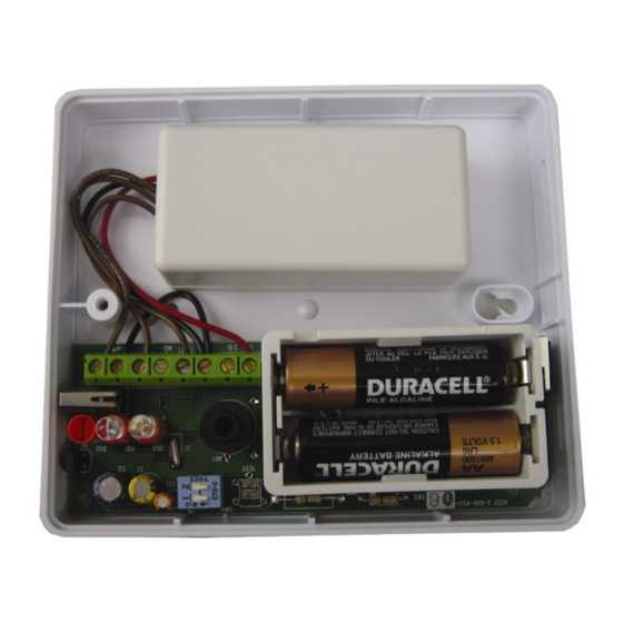
Tamper Switch Location: Refer to Figure 1 for the
location of the tamper switch on the Mini Door-
Window Contact.
Figure 1: Tamper Switch Location
2.3
Recessed Door-Window Contact
(ISW-BMC1-R135X)
Tamper Switch Location: Refer to Figure 2 for the
location of the tamper switch on the Recessed Door-
Window Contact.
Figure 2: Tamper Switch Location
2.4
Glassbreak Detector
(ISW-BGB1-SAX)
•
RF Signal Strength (RFSS) Mode LED
Location: Refer to Figure 3 for the location of the
LED that turns on when the detector enters RFSS
Mode.
Figure 3: RFSS Mode LED Location
wLSN
October 2006
Advertisement

Related Manuals for Bosch ISW-BMC1-M82X


Summary of Contents for Bosch ISW-BMC1-M82X
- Page 1 Detector: The magnet can be placed on either Figure 3: RFSS Mode LED Location side of these devices. Mini Door-Window Contact (ISW-BMC1-M82X) Tamper Switch Location: Refer to Figure 1 for the location of the tamper switch on the Mini Door- Window Contact.
- Page 2 Programmable Buttons: To operate the programmable buttons, press and hold either button for at least 1 sec. Refer to Figure 6. Figure 6: Programmable Button Locations Figure 5: Cover Tamper Switch Location © 2006 Bosch Security Systems, Inc. F01U032063B 10/06 www.boschsecuritysystems.com Release Notes...