
Related Manuals for Bosch MAP 5000 Series


Summary of Contents for Bosch MAP 5000 Series
- Page 1 MAP 5000 ICP‑MAP5000‑2 / ICP‑MAP5000‑COM / ICP‑MAP5000‑S / ICP‑MAP5000‑SC Installation manual...
-
Page 3: Table Of Contents
3.11 IP Interface Initial set-up and programming Initial set-up Programming 4.2.1 Help for the programming software 4.2.2 Standard-compliant programming Panel software 4.3.1 Checking the software version 4.3.2 Software updates Bosch Security Systems B.V. Installation manual 2019-09 | 25 | F.01U.168.332... - Page 4 8.3.1 Selecting the default setting 8.3.2 Automatic arming / disarming 8.3.3 Areas with blocking time 8.3.4 Access Levels 8.3.5 Tamper surveillance of the main panel Alarm reporting History log 2019-09 | 25 | F.01U.168.332 Installation manual Bosch Security Systems B.V.
-
Page 5: Introduction
When installing this system, ensure that all local and national wiring codes are met. – Only authorized service personnel is allowed to install this system. – Use only the installation material recommended by BOSCH Security Systems to ensure error-free operation. Bosch Security Systems B.V. Installation manual... -
Page 6: Planning The System
The ICP-MAP0115 power enclosure kit is designed to contain the following components: – IPP-MAP0005 power supply – ICP-MAP0065 AC terminal block – ICP-MAP0050 control panel enclosure tamper switch – Four batteries (maximum 40 Ah each) 2019-09 | 25 | F.01U.168.332 Installation manual Bosch Security Systems B.V. -
Page 7: Planning The System With Ipp-Map0005 Power Supply
4-wire cables are used for load connection within the power supply segment. The following conditions must be taken into account when planning in order to guarantee a reliable system booting: Bosch Security Systems B.V. Installation manual 2019-09 | 25 | F.01U.168.332... - Page 8 Refer to , page 10. Typical configuration with ICP-MAP0111 panel enclosure Main panel - DE module - 3 LSN gateway modules - max. 2 control centers 2019-09 | 25 | F.01U.168.332 Installation manual Bosch Security Systems B.V.
- Page 9 Short-time current limitation to 3.2 A per output A / B Current limitation to 1.6 A between internal and external BDB Remote operation with ICP-MAP0120 expansion enclosure Figure 1.4: 2 LSN modules with up to 4 control centers Bosch Security Systems B.V. Installation manual 2019-09 | 25 | F.01U.168.332...
- Page 10 For remote operation of the IPP-MAP0005 power supply, a control center assigned to the same area must be provided for indication of power supply trouble (trouble in mains supply / battery). 2019-09 | 25 | F.01U.168.332 Installation manual Bosch Security Systems B.V.
-
Page 11: Planning The System With Icp-Map0012 Can Splitter Module
The maximum cable length is 500 m per BDB connector. When planning the system with one or more CAN splitter modules, ensure to use an appropriate cable length and diameter in accordance with the necessary number of keypads. Bosch Security Systems B.V. Installation manual 2019-09 | 25 | F.01U.168.332... -
Page 12: System Overview
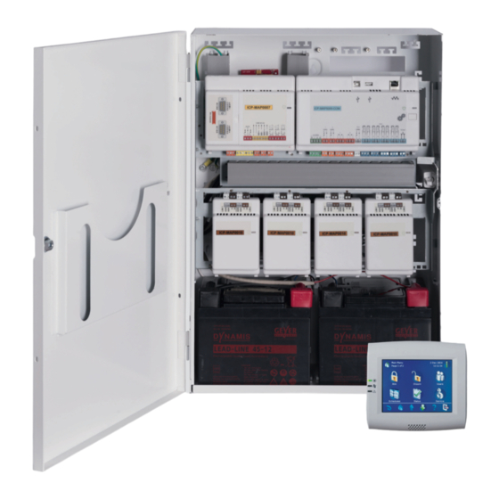
This chapter shows an overview of the system as it is installed in the ICP-MAP0111 control panel enclosure. System installation in ICP-MAP0111 panel enclosure (hinged mounting plate closed) ICP-MAP0111 2019-09 | 25 | F.01U.168.332 Installation manual Bosch Security Systems B.V. - Page 13 MAP 5000 Introduction | en System installation in ICP-MAP0111 panel enclosure (hinged mounting plate open) ICP-MAP0111 System installation in ICP-MAP0120 expansion enclosure Bosch Security Systems B.V. Installation manual 2019-09 | 25 | F.01U.168.332...
- Page 14 Mounting location for ICP-MAP0065 AC terminal block Earth ground connection points Flange for IPP-MAP0005 power supply Shielding connection points Knockout for AC wires (use when AC wires come in from the back of the enclosure) 2019-09 | 25 | F.01U.168.332 Installation manual Bosch Security Systems B.V.
-
Page 15: Installation
Remove the enclosure knockouts in the order shown in the figure below. Enclosure knockouts ICP-MAP0111 Element Description Knockout for wall tamper (required in accordance with EN50131 grade 3) Knockout for TAE box Knockouts for wiring Bosch Security Systems B.V. Installation manual 2019-09 | 25 | F.01U.168.332... -
Page 16: Installing The Tamper Switch Rail
Mount the tamper switch rail to the inner right side of the enclosure as shown in the figure below. Secure the tamper switch rail with the two supplied screws. Do not mount the tamper switch at this time. Mounting the tamper switch rail ICP-MAP0111 2019-09 | 25 | F.01U.168.332 Installation manual Bosch Security Systems B.V. -
Page 17: Mounting The Enclosure
Mount the enclosure to the intended surface using suitable screws and anchors (not supplied). Use the mounting holes as shown in the figure below. Ensure that all screws are tight and that the enclosure is securely fastened to the mounting surface. Bosch Security Systems B.V. Installation manual 2019-09 | 25 | F.01U.168.332... - Page 18 Mount the edge protection profile on the upper edge of the MAP enclosure from the left to the right. Ensure not to leave gaps at the cut-outs. Cut off the overlaying edge protection profile on the right side of the enclosure. 2019-09 | 25 | F.01U.168.332 Installation manual Bosch Security Systems B.V.
-
Page 19: Checking The Ac Connection
Align the cut-out on the right side of the power supply. Secure the power supply to the enclosure back wall with the supplied hardware in the following order: external tooth washer, washer, hex nut Bosch Security Systems B.V. Installation manual 2019-09 | 25 | F.01U.168.332... - Page 20 Installing the power supply ICP-MAP0111 IPP-MAP0005 IPP-MAP0005 power supply ratings label Put the power supply ratings label on the side of the power supply as shown in the picture below. 2019-09 | 25 | F.01U.168.332 Installation manual Bosch Security Systems B.V.
- Page 21 Put the power supply warning label on the enclosure back wall at the upper right side of the power supply as shown in the pictures below. ICP-MAP0111 Figure 2.1: Putting the power supply warning label into the ICP-MAP0111 and ICP-MAP0115 enclosure Bosch Security Systems B.V. Installation manual 2019-09 | 25 | F.01U.168.332...
- Page 22 Plug the terminal block connected to the AC terminal block into the power supply as shown in the figure below (2). Connect the ground wire to the ground connection point of the enclosure back wall as shown in the figure below (3). 2019-09 | 25 | F.01U.168.332 Installation manual Bosch Security Systems B.V.
-
Page 23: Installing The Tae Box
Installing the TAE box If the TAE Box is not mounted on the wall behind the enclosure, mount the TAE Box to the enclosure back wall either horizontally or vertically as desired. Bosch Security Systems B.V. Installation manual 2019-09 | 25 | F.01U.168.332... -
Page 24: Installing The Accessory Mounting Plate
Slide the clips on the back of the accessory mounting plate onto the top and bottom mounting rails. 2019-09 | 25 | F.01U.168.332 Installation manual Bosch Security Systems B.V. - Page 25 Ensure that the locking clips snap into the bottom mounting rail as shown in the figure below. Installing the accessory mounting plate Refer to Accessory mounting plate overview, page 26 for the locations of the modules that mount on the accessory mounting plate. Bosch Security Systems B.V. Installation manual 2019-09 | 25 | F.01U.168.332...
-
Page 26: Installing The 12 V Converter
(screws not supplied). Connect the field wiring to the terminal block of the 12 V converter as shown in the figure below and leave the other ends unconnected. 2019-09 | 25 | F.01U.168.332 Installation manual Bosch Security Systems B.V. -
Page 27: Installing The Fuse Plate (Siv)
Use the corresponding ratings for the fuses SI 1 ... SI 5. (minimum 250 mA, maximum 1 A depending on the connected loads). The overall current of all SIV outputs must not exceed the available maximum current of the voltage output used. Bosch Security Systems B.V. Installation manual 2019-09 | 25 | F.01U.168.332... -
Page 28: Installing The At 2000 Communicator
Notice! To ensure proper system grounding, you must insert the grounding screw through the AT 2000 and the accessory mounting plate. 2019-09 | 25 | F.01U.168.332 Installation manual Bosch Security Systems B.V. - Page 29 AT 2000 also requires a separate 12 V power source, such as the ICP-MAP0017 12 V converter. The ISDN AT 2000 requires 28 V. Use the ribbon cable connector labeled AT 2000 28V. Bosch Security Systems B.V. Installation manual 2019-09 | 25 | F.01U.168.332...
- Page 30 Analog AT 2000 to DE module connections Notice! The two trouble inputs are automatically configured to "Communicator Trouble" and "Negative Acknowledgment" when "Communicator" is selected in the Remote Programming Software (RPS). 2019-09 | 25 | F.01U.168.332 Installation manual Bosch Security Systems B.V.
- Page 31 MAP 5000 Installation | en Analog AT 2000 to ICP-MAP0017 12 V converter connections Bosch Security Systems B.V. Installation manual 2019-09 | 25 | F.01U.168.332...
- Page 32 | Installation MAP 5000 AT 2000 ISDN to DE module connections 2019-09 | 25 | F.01U.168.332 Installation manual Bosch Security Systems B.V.
-
Page 33: Installing The Hinged Mounting Plate
Installing the hinged mounting plate ICP-MAP0111 ICP-MAP0025 Mounting modules onto the hinged mounting plate The following graphic shows an overview of the hinged mounting plate and the designated mounting locations of the modules. Bosch Security Systems B.V. Installation manual 2019-09 | 25 | F.01U.168.332... - Page 34 ICP-MAP0007 ICP-MAP5000 ICP-MAP0025 ICP-MAP0010 ICP-MAP0012 Slide the module onto the hinged mounting plate. Ensure that the locking clips snap into a pair of rectangular openings on the bottom rail. 2019-09 | 25 | F.01U.168.332 Installation manual Bosch Security Systems B.V.
- Page 35 MAP 5000 Installation | en Sliding the module onto the hinged mounting plate Connect the grounding cable from the enclosure back wall to the hinged mounting plate. Bosch Security Systems B.V. Installation manual 2019-09 | 25 | F.01U.168.332...
-
Page 36: Mounting The Main Panel
How to mount the Ethernet cable Feed the Ethernet cable through the large snap ferrite sleeve (supplied in the accessory pack of the main panel) with an additional turn. 2019-09 | 25 | F.01U.168.332 Installation manual Bosch Security Systems B.V. -
Page 37: Installing The Icp-Com-If Relay Module
Attach the carrier plate of the ICP-COM-IF relay module in the holes provided in the hinged mounting plate or the mounting rails. Use the screw provided to secure the carrier plate to the bottom rail. Bosch Security Systems B.V. Installation manual 2019-09 | 25 | F.01U.168.332... -
Page 38: Installing And Connecting The Its-Map0008 Wireless Modem
R = red), in addition to existing wires where appropriate. Mount the small snap ferrite sleeve (contained in the accessory pack of the main panel) on the black-red cable of the wireless modem close to the wireless modem. 2019-09 | 25 | F.01U.168.332 Installation manual Bosch Security Systems B.V. - Page 39 Network login in progress 75 ms on, 3 s off Idle mode: The mobile is logged to the network (monitoring control channels and user interactions). No call in progress. Bosch Security Systems B.V. Installation manual 2019-09 | 25 | F.01U.168.332...
-
Page 40: Antennas
Area of use: inside, outside Rod antenna incl. 20 m cable. The mounting bracket is designed for mounting on vertical surfaces, the FME female connector is preconfigured 1) not for VdS 2019-09 | 25 | F.01U.168.332 Installation manual Bosch Security Systems B.V. -
Page 41: Connections
Always use the main panel as the first device on the data bus. The 120 ohm end terminator is already installed on every data bus. Connect a 120 ohm end terminator to the last device on each data bus. Bosch Security Systems B.V. Installation manual 2019-09 | 25 | F.01U.168.332... - Page 42 The order of system modules on the BDB shown in the figure is not mandatory. A symmetrical load distribution to the power supply outputs A and B must be ensured as far as possible. Data bus cable routing 120 Ω 2019-09 | 25 | F.01U.168.332 Installation manual Bosch Security Systems B.V.
-
Page 43: Internal / External Data Bus
BDB. 3.1.2 Topology of the external data bus Mount the external BDB as shown below. Notice! Any other bus topology doesn’t conform to the specifications of the BDB. Bosch Security Systems B.V. Installation manual 2019-09 | 25 | F.01U.168.332... -
Page 44: Splitting The External Data Bus With A Can Splitter Module
Only assign one area (where applicable with overlapping dependent partition areas) to a control center. Exception: Mutually independent areas may be assigned to the control center of the control panel area. 2019-09 | 25 | F.01U.168.332 Installation manual Bosch Security Systems B.V. -
Page 45: Connecting The Main Panel
Two programmable voltage outputs (28 V DC / 1 A) Two programmable dry relay outputs (toggle switches) Voltage output AUX (28 V DC / 1 A) Eight supervised inputs Input for panel tamper switch Bosch Security Systems B.V. Installation manual 2019-09 | 25 | F.01U.168.332... -
Page 46: Connecting The Power Supply
Connect the AC terminal block to the power supply. Connect the power supply to the main panel using the supplied four-pin connector cable (P/N: F01U074769). Connecting the power supply Connection Description 2019-09 | 25 | F.01U.168.332 Installation manual Bosch Security Systems B.V. -
Page 47: Connecting The Lsn Gateway
Looping the shield wire through the LSN elements Other connections of the additional shielding wire at other locations are not permitted. With loop wiring, the additional shielding wire must be connected at both loop ends. Bosch Security Systems B.V. Installation manual 2019-09 | 25 | F.01U.168.332... - Page 48 | Connections MAP 5000 LSN gateway loop configuration ICP-MAP0111 2019-09 | 25 | F.01U.168.332 Installation manual Bosch Security Systems B.V.
-
Page 49: Optional Connections
Optional power supply connections Connect the auxiliary DC power for the 12 V converter. Connect the supervision outputs. The supervision outputs monitor AC mains failure and summary power supply trouble. Bosch Security Systems B.V. Installation manual 2019-09 | 25 | F.01U.168.332... - Page 50 Connecting the power supply Optional DE module connections If a DR2020 printer is used, connect the DE module to the DR2020. Connect the supervised sirens and strobes to the DE module outputs. 2019-09 | 25 | F.01U.168.332 Installation manual Bosch Security Systems B.V.
-
Page 51: Installing And Connecting The Tamper Switch
> 5 mm leads to reliable activation of the tamper switch. Bosch Security Systems B.V. Installation manual 2019-09 | 25 | F.01U.168.332... - Page 52 53. For the ICP-MAP0120 enclosure, connect the ICP-MAP0055 expansion enclosure tamper switch to the ICP-MAP0005 power supply. Refer to Connecting the ICP-MAP0055 tamper switch, page 53. 2019-09 | 25 | F.01U.168.332 Installation manual Bosch Security Systems B.V.
-
Page 53: Installing The Icp-Map0060 Enclosure Lockset
Insert the lockset into the opening on the enclosure door as shown in the figure below (2). Secure the lockset with the nut as shown in the figure below (3). Bosch Security Systems B.V. Installation manual 2019-09 | 25 | F.01U.168.332... - Page 54 | Connections MAP 5000 Installing the enclosure lockset Connect the long grounding cable (P/N F01U074762) to the enclosure door. Connecting the grounding cable to the enclosure door 2019-09 | 25 | F.01U.168.332 Installation manual Bosch Security Systems B.V.
-
Page 55: Installing The Control Center
Ensure that there are no power-related trouble conditions. Warning! Ensure that the AC LED indicator on the power supply turns on steady before you connect the battery terminal to the power supply. Bosch Security Systems B.V. Installation manual 2019-09 | 25 | F.01U.168.332... -
Page 56: Ip Interface
In the MAP5000 panel menu, select -> setup: Management system as a Monitoring Station. Notice! Data transfer between the MAP 5000 and the connected PC system must always take place via a secure, authenticated and encrypted connection. 2019-09 | 25 | F.01U.168.332 Installation manual Bosch Security Systems B.V. -
Page 57: Initial Set-Up And Programming
Programming is performed with the program RPS for MAP. A PC or laptop with Windows XP SP3, Windows VISTA or Windows 7 is required for this. At least 256 MB RAM is needed. A mouse is recommended for operation of the program. Bosch Security Systems B.V. Installation manual 2019-09 | 25 | F.01U.168.332... -
Page 58: Help For The Programming Software
After first start-up, you need to check whether the software versions of all system modules and the programming software are compatible with each other (refer to MAP 5000 system bundles). 2019-09 | 25 | F.01U.168.332 Installation manual Bosch Security Systems B.V. -
Page 59: Software Updates
Overview of the Standard Point Types and their pre-set properties Point Type Arming state Influences ready to arm status Disarmed Internal armed External armed Intrusion Intrusion 24 h Hold-up Amok Duress Tamper Bosch Security Systems B.V. Installation manual 2019-09 | 25 | F.01U.168.332... -
Page 60: Output Functions
Shows the actual status of the input: normal / active Report failure panel alarm Panel has received negative acknowledgment from (V1.2x) communicator as a result of report failure panel alarm (only for panel firmware 1.2.x) 2019-09 | 25 | F.01U.168.332 Installation manual Bosch Security Systems B.V. - Page 61 Motion detector test is active in one or more areas Exit delay active From start of exit delay until – end of exit delay – arming of the area Bosch Security Systems B.V. Installation manual 2019-09 | 25 | F.01U.168.332...
- Page 62 Open Intrusion Interface Trouble in connection via Open Intrusion Interface Trouble Silence Area x Silence sirens and buzzer of area x Reset Area x Clear events of area x 2019-09 | 25 | F.01U.168.332 Installation manual Bosch Security Systems B.V.
-
Page 63: Sirens And Communicator In Accordance With En50131 Grade 3
Outputs R1 – R7 on ICP-COM-IF or other outputs on panel Notice! Both communicators may be connected to the same outputs. Variant D (ICP-COM-IF required) – One communicator class 5 Outputs R1 – R7 on ICP-COM-IF Bosch Security Systems B.V. Installation manual 2019-09 | 25 | F.01U.168.332... -
Page 64: Enclosure Options
P/N: F0U124597 ICP-MAP0115 ICP-MAP0130 P/N: F0U124597 ICP-MAP0050 BAT1 ICP-MAP0065 BAT2 IPP-MAP0005 Connect the ICP-MAP0115 power enclosure to the ICP-MAP0111 enclosure to provide additional power when high power capacity is required. 2019-09 | 25 | F.01U.168.332 Installation manual Bosch Security Systems B.V. -
Page 65: Rack Mount Option For Icp-Map0120 Expansion Enclosure
To install the ICP-MAP0120 expansion enclosure in a 19-inch rack, connect the ICP- MAP0035 rack mount brackets to the ICP-MAP0120 expansion enclosure. Installing the rack mount brackets to the ICP-MAP0120 expansion enclosure Bosch Security Systems B.V. Installation manual 2019-09 | 25 | F.01U.168.332... -
Page 66: Maintenance And Service
Notice! Have maintenance and inspection work carried out regularly by trained expert personnel. Bosch Sicherheitssysteme GmbH recommends performing a functional and visual inspection at least once annually. Danger! Danger of electric shock if live parts are touched. For your safety, you should switch off the... - Page 67 Programming, panel firmware and history are deleted and network settings are reset (DHCP, 0.0.0.0) when executing this option. Carry out steps 1 – 6 of the above, then carry out steps 2 – 7. Bosch Security Systems B.V. Installation manual 2019-09 | 25 | F.01U.168.332...
-
Page 68: Technical Specifications
Dimension in cm (H x W x D) 43.6 x 44.3 x 11.2 Weight in g System parameters Number of addresses 1500 Number of areas Event log capacity 4000 Users Number of users 1000 2019-09 | 25 | F.01U.168.332 Installation manual Bosch Security Systems B.V. - Page 69 1, RJ 45 connection Management system connection Via Ethernet interface and the Open Intrusion Interface OII or the MAP OPC server from Bosch - in VdS systems, only feedback-free connection as information system via exclusive transmission path Number of inputs...
- Page 70 | Technical Specifications MAP 5000 Maximum relative humidity in % Protection class IP30 IP31 (with an edge protection profile) Security level IK06 Environmental class EN60950-1, EN50130-4, EN50131-1, VdS 2110 Usage Indoor 2019-09 | 25 | F.01U.168.332 Installation manual Bosch Security Systems B.V.
-
Page 71: Appendices
AE 3 Access for installers via control center Open control panel enclosure. Switch to installer mode (refer to Installer button, page 66). Enter installer passcode. AE 3 Access for installers via RPS for MAP Bosch Security Systems B.V. Installation manual 2019-09 | 25 | F.01U.168.332... - Page 72 May change schedule May edit blocking time User category permissions May add user May delete user May change user passcode Event category permissions May clear internal alarm May clear external alarm 2019-09 | 25 | F.01U.168.332 Installation manual Bosch Security Systems B.V.
- Page 73 May adjust control center volume/brightness May change output state May set date time May test bell May test motion detectors May walk test automatic points May walk test points Tab. 8.2: Permissions Bosch Security Systems B.V. Installation manual 2019-09 | 25 | F.01U.168.332...
-
Page 74: Connection Of An Lsn Fire Detector As A Technical Detector
In the properties field of the Control Center, include the area in the scope Local Area or Additional Areas in Scope Programming two outputs for signaling the armed / disarmed state Connect one free output in each case with the device LED. 2019-09 | 25 | F.01U.168.332 Installation manual Bosch Security Systems B.V. -
Page 75: Arming / Disarming With Entry / Exit Delay
Door point that shortens the running exit delay to 10 sec. (recommended) Restart Point that restarts the exit delay; possible only once during the exit Tab. 8.3: Exit point types Not for EN 50131 Bosch Security Systems B.V. Installation manual 2019-09 | 25 | F.01U.168.332... -
Page 76: Arming With Automatic Bypass
30 seconds) for Activation Duration. Automatic arming at a predefined time: defining the arming time Start the schedule wizard and define the time of arming. As action, select Arm Area(s) Using Exit Delay. 2019-09 | 25 | F.01U.168.332 Installation manual Bosch Security Systems B.V. -
Page 77: Alarm Output Via Siren And Communicator
AE 2 Access for users, user passcode required – AE 3 Access for installers via control center or via RPS for MAP – AE 4 Access for manufacturers via RPS for MAP Bosch Security Systems B.V. Installation manual 2019-09 | 25 | F.01U.168.332... - Page 78 Further subdivisions are possible within the access levels if the owner wishes to grant the users different permissions: User Manager > Permission Sets General permissions Access level May silence buzzer on control center May change own user passcode May transmit/receive programming with RPS 2019-09 | 25 | F.01U.168.332 Installation manual Bosch Security Systems B.V.
- Page 79 Can disarm only if in alarm May bypass detectors May bypass detectors in area May unbypass detector May switch internal program on/off Status category permissions May view area status May view device status Bosch Security Systems B.V. Installation manual 2019-09 | 25 | F.01U.168.332...
-
Page 80: Additional Functions Of The Main Panel
Select Control Center > Behavior >Outputs Available For Direct Command. Automatic via schedule Using the schedule wizard, enter the time when the output is to be switched on/off. As action, select Output ON or Output OFF. 2019-09 | 25 | F.01U.168.332 Installation manual Bosch Security Systems B.V. -
Page 81: Requirements In Accordance With Ses
Disarming at a predefined time Automatic disarming is not permitted for security reasons. See also – Automatic arming / disarming, page 76 – Arming with automatic bypass, page 76 Bosch Security Systems B.V. Installation manual 2019-09 | 25 | F.01U.168.332... -
Page 82: Areas With Blocking Time
Switch to installer mode = AE 3 (Installer button, page 66). Login with the passcode of the manufacturer at the installer control center (Manufacturer authorization, page 59). Establish a connection between the panel and RPS. 2019-09 | 25 | F.01U.168.332 Installation manual Bosch Security Systems B.V. - Page 83 May add user May delete user May change user passcode Event category permissions May clear internal alarm May clear external alarm May clear tamper May clear trouble May clear battery trouble Bosch Security Systems B.V. Installation manual 2019-09 | 25 | F.01U.168.332...
- Page 84 May test bell May test motion detectors May walk test automatic points May walk test points Tab. 8.6: SES Permissions See also – Installer button, page 66 – Manufacturer authorization, page 59 2019-09 | 25 | F.01U.168.332 Installation manual Bosch Security Systems B.V.
-
Page 85: Tamper Surveillance Of The Main Panel
ICP-MAP5000-COM and ICP-MAP5000-SC have an integrated alarm reporting functionality. It can be used for alarm transmission systems according to EN50136-2 SP4 or DP3. For DP3 compliant transmission, the alternate transmission path has to be wireless. Bosch Security Systems B.V. Installation manual 2019-09 | 25 | F.01U.168.332... -
Page 86: History Log
For both history logs there is no duration defined. This means, that events are stored for an unlimited amount of time and are not affected in case of power loss at the panel. 2019-09 | 25 | F.01U.168.332 Installation manual Bosch Security Systems B.V. - Page 87 MAP 5000 Appendices | Bosch Security Systems B.V. Installation manual 2019-09 | 25 | F.01U.168.332...
- Page 88 | Appendices MAP 5000 2019-09 | 25 | F.01U.168.332 Installation manual Bosch Security Systems B.V.
- Page 90 Bosch Security Systems B.V. Torenallee 49 5617 BA Eindhoven Netherlands www.boschsecurity.com © Bosch Security Systems B.V., 2019...