
Related Manuals for Siemens FDM1101-R Series


Summary of Contents for Siemens FDM1101-R Series
- Page 1 FDM1101-Rx Manual call point collective Technical Manual Building Technologies A6V10201150_d_en_-- 2018-12-19 Control Products and Systems...
- Page 2 Issued by: Siemens Switzerland Ltd. Building Technologies Division International Headquarters Theilerstrasse 1a CH-6300 Zug Tel. +41 58 724-2424 www.siemens.com/buildingtechnologies Edition: 2018-12-19 Document ID: A6V10201150_d_en_-- © Siemens Switzerland Ltd, 2008 2 | 32 Building Technologies A6V10201150_d_en_-- Fire Safety 2018-12-19...
-
Page 3: Table Of Contents
Table of contents About this document ................5 Applicable documents ................. 7 Download center ..................7 Technical terms and abbreviations .............. 7 History of changes ..................8 Safety ....................9 Safety instructions ..................9 Safety regulations for the method of operation ...........11 Standards and directives complied with............13 Release Notes ...................13 Structure and function ................. - Page 4 Mounting / Installation ................23 Installation ....................25 Commissioning ...................26 Maintenance / Repair ................27 Performance check ..................27 Testing detector with the key ..............27 Replacing the glass insert ................28 Spare parts ....................28 Specifications ..................29 Technical data ................... 29 Dimensions ....................
-
Page 5: About This Document
About this document Applicable documents 1 About this document Goal and purpose This document includes all information on the manual call points FDM1101-Rx. Following the instructions consistently will ensure that the product can be used safely and without any problems. Target groups The information in this document is intended for the following target groups: Target group... - Page 6 About this document Applicable documents Source language and reference document ● The source/original language of this document is German (de). ● The reference version of this document is the international version in English. The international version is not localized. Document identification The document ID is structured as follows: ID code Examples...
-
Page 7: Applicable Documents
You can download various types of documents, such as data sheets, installation instructions, and license texts via the following Internet address: http://siemens.com/bt/download Enter the document ID in the 'Find by keyword' input box. You will also find information about search variants and links to mobile applications (apps) for various systems on the home page. -
Page 8: History Of Changes
About this document History of changes 1.4 History of changes The reference document's version applies to all languages into which the reference document is translated. The first edition of a language version or a country variant may, for example, be version 'd' instead of 'a' if the reference document is already this version. -
Page 9: Safety
Safety Safety instructions 2 Safety 2.1 Safety instructions The safety notices must be observed in order to protect people and property. The safety notices in this document contain the following elements: ● Symbol for danger ● Signal word ● Nature and origin of the danger ●... - Page 10 Safety Safety instructions How risk of injury is presented Information about the risk of injury is shown as follows: WARNING Nature and origin of the danger Consequences if the danger occurs ● Measures / prohibitions for danger avoidance How possible damage to property is presented Information about possible damage to property is shown as follows: NOTICE Nature and origin of the danger...
-
Page 11: Safety Regulations For The Method Of Operation
2.2 Safety regulations for the method of operation National standards, regulations and legislation Siemens products are developed and produced in compliance with the relevant European and international safety standards. Should additional national or local safety standards or legislation concerning the planning, mounting, installation,... - Page 12 Disregard of the safety regulations Before they are delivered, Siemens products are tested to ensure they function correctly when used properly. Siemens disclaims all liability for damage or injuries caused by the incorrect application of the instructions or the disregard of danger warnings contained in the documentation.
-
Page 13: Standards And Directives Complied With
Safety Standards and directives complied with 2.3 Standards and directives complied with A list of the standards and directives complied with is available from your Siemens contact. 2.4 Release Notes Limitations to the configuration or use of devices in a fire detection installation with a particular firmware version are possible. -
Page 14: Structure And Function
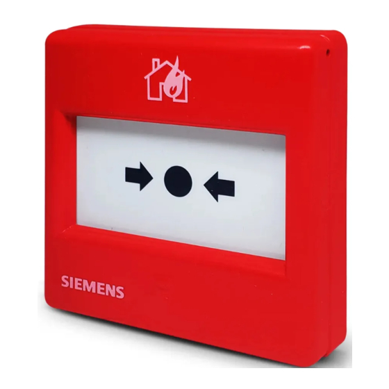
Structure and function Overview 3 Structure and function 3.1 Overview Figure 1: Overview of FDM1101-Rx 1 Key FDMK295 4 Switching unit 2 Cover cap 5 Supplied screws 3 Plastic insert or glass insert 6 Accessories: Back box FDMH295-R or back box FDMH295-S The manual call points FDM1101-Rx are for manually activating alarms in the case of fire. -
Page 15: Product Version Es
Structure and function Overview 3.1.1 Product version ES The product version ES provides the technical status of a device in terms of software and hardware. The product version is provided as a two-digit number. You will find the details of your device's product version: ●... -
Page 16: Setup
Structure and function Setup 3.2 Setup 3.2.1 Connections The back of the manual call points FDM1101-Rx is fitted with 4 terminals for the detector line. At the end of the collective detector line, a control-panel-specific end- of-line element (EOL) must be connected to the terminals. LINE LINE FDM1101-Rx... -
Page 17: Function
Structure and function Function 3.3 Function 3.3.1 Danger levels The manual call point can transmit the following danger levels to the control panel: Danger level Meaning Normal state, no danger Alarm The evaluation of the danger level and the resulting measures (e.g. activation of remote transmission) are configured on the control panel. -
Page 18: Accessories
Structure and function Accessories 3.4 Accessories 3.4.1 Key A key is enclosed in the delivery of each manual call point. See also 2 Key FDMK295 [➙ 19] 3.4.2 'NOT IN USE' label A 'NOT IN USE' label is enclosed in the delivery of each manual call point. ●... -
Page 19: Optional Accessories
Structure and function Accessories 3.4.5 Optional accessories This chapter lists all spare parts with their ordering numbers, in addition to the optional accessories. Detailed information on the accessories enclosed in the delivery can also be found here. 3.4.5.1 Key FDMK295 ●... -
Page 20: Glass Inserts Fdmg295-X
Structure and function Accessories 3.4.5.4 Glass inserts FDMG295-x ● For alarm activation and protection against soiling ● Available in country-specific designs ● Compatible with: – Manual call point FDM1101-Rx – Manual call point FDM1101A-Rx – Manual call point FDM225-Rx – Manual call point FDM226-Rx –... -
Page 21: Metal Cable Gland M20 X 1.5
Structure and function Accessories 3.4.5.7 Metal cable gland M20 x 1.5 ● Compatible with back boxes ● Order number (10 pcs. per pack): A5Q00004478 3.4.5.8 M20 x 1.5 metal counter nut ● For use with metal cable gland M20 x 1.5 ●... -
Page 22: Project Engineering
Project engineering Compatibility 4 Project engineering 4.1 Compatibility Compatible with all fire detection systems with collective/SynoLINE600 signal processing. Refer to 'List of compatibility' (doc. no. 008331) for details. 4.2 Ranges of application The manual call points are intended for use in places where a fire can be detected by people who can manually trigger an alarm. -
Page 23: Mounting / Installation
Mounting / Installation Environmental influences 5 Mounting / Installation Preparation If using back box FDMH295-R, you have to determine the positions of the lead-in openings. If the lead-in openings are on the top or bottom, you must determine them with the drilling jig (product insert). Procedure Figure 6: Mounting Note the positive and negative poles! - Page 24 Mounting / Installation Environmental influences WARNING Deactivating the manual call points prevents alarms from being forwarded. The alarm is not triggered. ● Deactivated manual call points must be labeled with the 'NOT IN USE' notice! LINE LINE FDM1101-Rx Figure 7: Detector line connection diagram EOL Line termination element (End Of Line) 24 | 32 Building Technologies...
-
Page 25: Installation
Mounting / Installation Installation 5.1 Installation Notes on work on electrical installations ● Specialist electrical engineering knowledge is required for installation. ● Only an expert is permitted to carry out installation work. Incorrect installation can take safety devices out of operation unbeknown to a layperson. -
Page 26: Commissioning
Commissioning 6 Commissioning The collective detector line is commissioned on the control panel. The exact procedure is described in the control panel documentation. 26 | 32 Building Technologies A6V10201150_d_en_-- Fire Safety 2018-12-19... -
Page 27: Maintenance / Repair
Maintenance / Repair Performance check 7 Maintenance / Repair 7.1 Performance check The devices are automatically subjected to a performance check during the self- test. Nevertheless, it is necessary to check the devices on site at regular intervals. Recommendation: ● Check the devices every year. -
Page 28: Replacing The Glass Insert
Maintenance / Repair Replacing the glass insert 7.3 Replacing the glass insert The glass insert is covered by a foil. This foil holds the glass splinters together when the glass insert is pushed in, making it possible to remove the glass insert easily. -
Page 29: Specifications
Specifications Technical data 8 Specifications 8.1 Technical data Detector line Operating voltage DC 16…26 V Quiescent current 0.01 mA Alarm current (permanent, maximum) 60 mA Alarm current (pulsating) 100 mA Maximum current connection factor Quiescent current connection factor Protocol Collective (SynoLINE600) Compatibility Refer to document 'List of compatibility';... -
Page 30: Dimensions
Specifications Dimensions 8.2 Dimensions 35.5 Figure 10: Dimensional drawings for FDM1101-Rx and back box FDMH295-R / FDMH295-S 8.3 Environmental compatibility and disposal This equipment is manufactured using materials and procedures which comply with current environmental protection standards as best as possible. More specifically, the following measures have been undertaken: ●... -
Page 31: Index
Index Index Alarm indicator Testing detectors ........27, 27 Red LED ............16 Application area Ambient conditions.......... 22 Maintenance intervals ........27 Manual call point Test mode ............17 Back box Surface-mounted feed lines ......14 Original language ..........6 Collective Communication .......... - Page 32 © Siemens Switzerland Ltd, 2008 Issued by Siemens Switzerland Ltd Technical specifications and availability subject to change without notice. Building Technologies Division International Headquarters Theilerstrasse 1a CH-6300 Zug +41 58 724 2424 www.siemens.com/buildingtechnologies Document ID: A6V10201150_d_en_-- DS11.1 Edition: 2018-12-19...