
Related Manuals for Siemens FDM273


Summary of Contents for Siemens FDM273
- Page 1 FDM273 Radio manual call point Mounting Smart Infrastructure A6V10347888_h_en_-- 2020-03-31...
- Page 2 All rights created by patent grant or registration of a utility model or design patent are reserved. Issued by: Siemens Switzerland Ltd. Smart Infrastructure Global Headquarters Theilerstrasse 1a CH-6300 Zug Tel. +41 58 724-2424 www.siemens.com/buildingtechnologies Edition: 2020-03-31 Document ID: A6V10347888_h_en_-- © Siemens Switzerland Ltd, 2013 2 | 18 A6V10347888_h_en_--...
-
Page 3: Table Of Contents
Table of contents About this document................. Mounting and installation................Preparation ....................Installing the housing................Installation ....................Installing the protective cover ..............Inserting the door sign ................Details for ordering ................... Switching unit FDME273 ................Housing FDMH273-R ................Battery pack BAT3.6-10 ................Key DMZ1195................... - Page 4 4 | 18 A6V10347888_h_en_--...
-
Page 5: About This Document
1 About this document Overview The FDM273 radio manual call point is intended for use in areas of a house where a fire can be detected by people who can manually trigger an alarm. The FDM273 radio manual call point consists of a housing, a switching unit, and a battery pack. -
Page 6: Mounting And Installation
Mounting and installation Preparation 2 Mounting and installation 2.1 Preparation Secure the housing at a height of 0.9…1.6 m on an even surface. Observe the country-specific regulations for the exact mounting height! 180° Figure 1: Opening the housing and identifying the screw holes 1 Screw opening 3 Break-out points 2 Door sign... -
Page 7: Installing The Housing
Mounting and installation Installing the housing 2.2 Installing the housing 2,5...3 mm >8 mm Figure 2: Example of securing onto the substructure using two screws The housing is ready for mounting. See the chapter 'Preparation'. Screw the housing securely onto the substructure using two screws. The housing has been installed. -
Page 8: Installation
Mounting and installation Installation 2.3 Installation 1 Screws 6 Battery pack BAT3.6-10 2 Switching unit FDME273 7 Holders 3 Battery connector 8 Locking lever 4 Housing FDMH273-R 9 Internal alarm indicator 5 Door 10 Alarm button Not included in the scope of delivery The flashing behavior of the internal alarm indicator is described in document A6V10347733 in the 'Internal alarm indicator' chapter. - Page 9 2. Remove the adhesive label with the serial number from the type plate on the switching unit. Use the adhesive label to mark the position of the radio manual call point FDM273 on the device location plan. 3. Turn over the window sign if necessary, or use a different one.
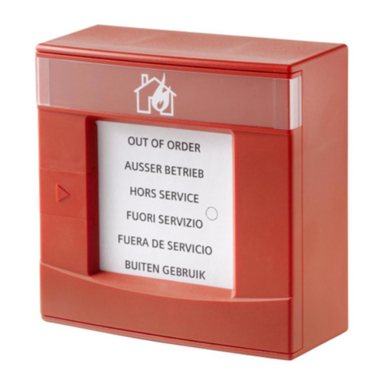
- Page 10 Mounting and installation Installation OUT OF ORDER AUSSER BETRIEB HORS SERVICE FUORI SERVIZIO FUERA DE SERVICIO BUITEN GEBRUIK Figure 3: 'NOT IN USE' label 10 | 18 A6V10347888_h_en_--...
-
Page 11: Installing The Protective Cover
Mounting and installation Installing the protective cover 2.4 Installing the protective cover If a protective cover (accessories) is used, proceed as follows: A compatible protective cover is available. See the chapter 'Accessories'. 1. Open the door of the manual call point. 2. -
Page 12: Inserting The Door Sign
Mounting and installation Inserting the door sign 2.5 Inserting the door sign Only use the door sign if local regulations require the manual call point to be labeled in this way. The appropriate door sign (printed on both sides) is available. 1. -
Page 13: Details For Ordering
● Inscription field for commissioning date ● Compatible with: – Radio gateway FDCW241 – Radio manual call point FDM273 – Radio manual call point FDM275 – Radio manual call point FDM275(F) – Radio fire detector FDOOT271 ● Order number: S54370-Z11-A1... -
Page 14: Key Dmz1195
For opening doors on manual call points ● Compatible with: – Manual call point FDM223 – Manual call point FDM224 – Radio manual call point FDM273 ● Order number: BPZ:4851910001 3.5 Glass insert DMZ1196-AC ● For alarm activation and protection against soiling ●... -
Page 15: Specifications
Specifications Technical data 4 Specifications 4.1 Technical data You will find information on approvals, CE marking, and the relevant EU directives for this device (these devices) in the following document(s); see 'Applicable documents' chapter: ● Document A6V10271323 Device characteristics Detector diagnosis With FXS2061 SWING Tool or connected fire control panel Type of alarm activation... -
Page 16: Dimensions
● FDMH273-R 0.279 kg ● FDME273 0.098 kg Housing material: ● FDMH273-R Polycarbonate (PC) Colors: ● FDMH273-R ~RAL 3000 flame red Standards European standards ● EN 54-11 ● EN 54-25 ● EN 300220-2 ● EN 301489-3 ● EN 60950 4.2 Dimensions Radio manual call point FDM273 16 | 18 A6V10347888_h_en_--... -
Page 17: Master Gauge For Recesses
Specifications Master gauge for recesses 4.3 Master gauge for recesses Radio manual call point FDM273 61.5 37.5 37.4 61.8 27.8 4.4 Environmental compatibility and disposal This equipment is manufactured using materials and procedures which comply with current environmental protection standards as best as possible. - Page 18 © Siemens Switzerland Ltd, 2013 Issued by Siemens Switzerland Ltd Technical specifications and availability subject to change without notice. Smart Infrastructure Global Headquarters Theilerstrasse 1a CH-6300 Zug +41 58 724 2424 www.siemens.com/buildingtechnologies A6V10347888_h_en_--...