Table of Contents
Advertisement
Quick Links
QQ
3 7 63 1515 0
SERVICE MANUAL
Ver 1.0 2000. 08
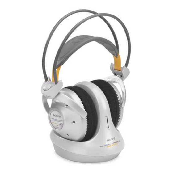
TMR-RF875R is the component model block one in the MDR-RF875RK.
COMPONENT MODEL NAME FOR MDR-RF875RK
Headphones
MDR-RF875R
Transmitter
TMR-RF875R
TE
L 13942296513
www
.
http://www.xiaoyu163.com
TMR-RF875R
General
Carrier frequency
Channel
Modulation
Frequency response
Transmitter
Power source
Audio input
Dimensions
Mass
Design and specifications are subject to change without
notice.
x
ao
u163
y
i
http://www.xiaoyu163.com
2 9
8
Q Q
3
6 7
1 3
1 5
SPECIFICATIONS
863.5 – 864.5 MHz
Ch1, Ch2, Ch3
FM stereo
18 – 22,000 Hz
DC 9 V: supplied AC power
adaptor
phono jacks/stereo mini jack
Approx. 130 × 135 × 150 mm
× 5
× 6 in.) (w/h/d)
1
3
(5
/
/
4
8
Approx. 200 g (7 oz.)
co
.
9 4
2 8
AEP Model
UK Model
0 5
8
2 9
9 4
2 8
m
TRANSMITTER
9 9
9 9
Advertisement
Table of Contents

Related Manuals for Sony MDR-RF875R


Summary of Contents for Sony MDR-RF875R
- Page 1 3 7 63 1515 0 SERVICE MANUAL AEP Model UK Model Ver 1.0 2000. 08 TMR-RF875R is the component model block one in the MDR-RF875RK. COMPONENT MODEL NAME FOR MDR-RF875RK Headphones MDR-RF875R Transmitter TMR-RF875R L 13942296513 SPECIFICATIONS General Carrier frequency 863.5 – 864.5 MHz...
- Page 2 http://www.xiaoyu163.com SECTION 1 This section is extracted from instruction manual. GENERAL 3 7 63 1515 0 Setting up the transmitter Connect the transmitter to audio/video equipment. Select one of the hookups below depending on the jack type: A To connect to a headphone jack Transmitter to AUDIO IN A jacks...
-
Page 3: Housing (Upper)
http://www.xiaoyu163.com SECTION 2 DISASSEMBLY 3 7 63 1515 0 Note : Follow the disassembly procedure in the numerical order given. 2-1. HOUSING (UPPER) Housing (upper) L 13942296513 × 8) 1 Four screws (P 2 2-2. TX-BASE BOARD 2-3. CHG-NR BOARD Housing (upper) Housing (upper) Screw... -
Page 4: Section 3 Electrical Adjustments
http://www.xiaoyu163.com SECTION 3 ELECTRICAL ADJUSTMENTS 3 7 63 1515 0 Setting : Pilot Signal and MPX Signal Modulation Check and Adjustment 1. Set the channel to CH2. AF signal 2. No signal input (The operating time in this case is limited to 4 generator or 5 minutes.) 3. - Page 5 http://www.xiaoyu163.com TMR-RF875R SECTION 4 DIAGRAMS 3 7 6 3 1 5 1 5 0 4-1. BLOCK DIAGRAM MODULATION D408 RV401 IC403 STEREO MPX ANT401 Q403 IC401 IC601 R-CH RV402 RV403 J401 BUFFER SWITCH MOD IN TIME DEVISION MODULATION MODULATION AUDIO IN J402 R-CH IC405(2/2)
- Page 6 http://www.xiaoyu163.com TMR-RF875R • See page 6 for Note on Schematic Diagrams. 4-2. SCHEMATIC DIAGRAM –MAIN SECTION– 3 7 6 3 1 5 1 5 0 RV401-403, L407 MODULATION 1 3 9 4 2 2 9 6 5 1 3 w w w u 1 6 3 —...
- Page 7 http://www.xiaoyu163.com TMR-RF875R • See page 6 for Note on Printed Wiring Board. 4-3. PRINTED WIRING BOARD –MAIN SECTION– 3 7 6 3 1 5 1 5 0 • Semiconductor Location Ref. No. Location D401 D402 D403 D404 D405 D407 D408 D410 IC401 IC402...
- Page 8 http://www.xiaoyu163.com TMR-RF875R • See page 6 for Note on Schematic Diagrams. 4-4. SCHEMATIC DIAGRAM –BATTERY CHARGER SECTION– 3 7 6 3 1 5 1 5 0 1 3 9 4 2 2 9 6 5 1 3 IC601,IC602 TK10690M IC603 TB1004AF 22BIT COUNTER 10 VDD...
- Page 9 http://www.xiaoyu163.com TMR-RF875R • See page 6 for Note on Printed Wiring Board. 4-5. PRINTED WIRING BOARD –BATTERY CHARGER SECTION– 3 7 6 3 1 5 1 5 0 • Semiconductor Location Ref. No. Location D601 IC601 IC602 IC603 IC604 IC605 Q601 Q602 Q603...
-
Page 10: Section 5 Exploded Views
http://www.xiaoyu163.com SECTION 5 EXPLODED VIEWS 3 7 63 1515 0 NOTE: • -XX, -X mean standardized parts, so they may • The mechanical parts with no reference number have some differences from the original one. in the exploded views are not supplied. •... -
Page 11: Section 6 Electrical Parts List
http://www.xiaoyu163.com SECTION 6 TX-BASE ELECTRICAL PARTS LIST 3 7 63 1515 0 NOTE: • Due to standardization, replacements in the • CAPACITORS: • SEMICONDUCTORS parts list may be different from the parts uF: µF In each case, u: µ, for example: specified in the diagrams or the components •... - Page 12 http://www.xiaoyu163.com TX-BASE CHG-NR 3 7 63 1515 0 Ref. No. Part No. Description Remarks Ref. No. Part No. Description Remarks < COIL > R454 1-216-073-00 METAL CHIP 1/10W R455 1-216-077-00 RES-CHIP 1/10W L401 1-414-234-11 INDUCTOR CHIP 0uH R456 1-216-051-00 METAL CHIP 1.2K 1/10W L402...
- Page 13 2SB1386-T100-R Q602 1-801-806-11 TRANSISTOR DTC144EKA-T146 Q603 8-729-027-40 TRANSISTOR DTA144VKA-T146 Q604 1-801-806-11 TRANSISTOR DTC144EKA-T146 Q605 8-729-903-10 TRANSISTOR FMW1 u163 Sony Corporation 2000H1646-1 Audio Entertainment Group 9-927-966-11 Printed in Japan © 2000.8 — 18 — Published by PE General Engineering Dept. http://www.xiaoyu163.com...