Sony MDR-RF875RK Service Manual
Hide thumbs
Also See for MDR-RF875RK:
- Operating instructions manual (12 pages) ,
- Service manual (2 pages)
Table of Contents
Advertisement
SERVICE MANUAL
Ver 1.0 2000. 08
MDR-RF875R is the component model block one in the MDR-RF875RK.
COMPONENT MODEL NAME FOR MDR-RF875RK
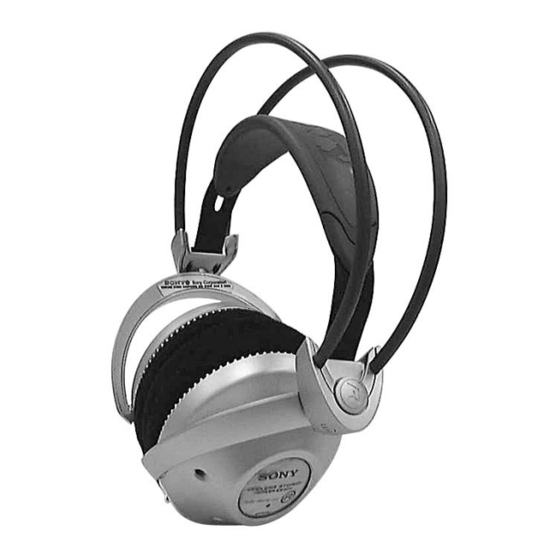
Headphones
MDR-RF875R
Transmitter
TMR-RF875R
MDR-RF875R
SPECIFICATIONS
Headphones
Power source
DC 2.4 V: Built-in rechargeable
battery
Mass
Approx. 350 g (12.25 oz.) incl.
built-in rechargeable battery
Built-in Ni-MH rechargeable battery
Model name
NH-AAC
Voltage
1.2 V
Capacity
1,000 mAh
Design and specifications are subject to change without
notice.
AEP Model
UK Model
HEADPHONES
Advertisement
Table of Contents

Related Manuals for Sony MDR-RF875RK


Summary of Contents for Sony MDR-RF875RK
- Page 1 MDR-RF875R SERVICE MANUAL AEP Model UK Model Ver 1.0 2000. 08 MDR-RF875R is the component model block one in the MDR-RF875RK. COMPONENT MODEL NAME FOR MDR-RF875RK Headphones MDR-RF875R Transmitter TMR-RF875R SPECIFICATIONS Headphones Power source DC 2.4 V: Built-in rechargeable battery Mass Approx.
-
Page 2: Section 1 General
SECTION 1 This section is extracted from instruction manual. GENERAL Auto power on/off function Turn up the volume to a moderate When you remove the headphones from your level with the VOL control. head, the power turns off automatically. Do not Press the TUNING button briefly for allow the self adjusting band to be pulled up, automatic tuning of the headphones. -
Page 3: Section 2 Disassembly
SECTION 2 DISASSEMBLY • The equipment can be removed using the following procedure. Driver (R side), RX-BASE board SW board, Harger (R) Holder (R) Driver (L side), Hanger (L) Holder (L) Note : Follow the disassembly procedure in the numerical order given. 2-1. -
Page 4: Sw Board, Hanger (R)
2-2. SW BOARD, HANGER (R) 3 Hanger lid (R) 5 Holder lid (R) 4 Two screws × 8) 8 SW board (P 2 2 Housing (R) 7 Remove the two solderings. Precaution for installtion Set the each leads as illustrated below. From 9 Hanger (R) SW board. -
Page 5: Driver (L Side)
2-4. DRIVER (L SIDE) Set the each leads as illustrated below. From head band assy (front). Groove Groove From head Housing (L) band assy (rear). Precaution for installtion 8 Driver 6 Ear pad 3 Front plate (L) assy holder (L) 1 Ear pad Four claws... - Page 6 2-5. HANGER (L) 5 Holder lid (L) 3 Hanger lid (L) 2 Housing (L) 4 Two screws × 5) (M 2 Precaution for installtion Set the each leads as illustrated below. 7 Hanger (L) Groove Hanger (L) Groove From head Groove band assy (front).
-
Page 7: Section 3 Electrical Adjustments
SECTION 3 ELECTRICAL ADJUSTMENTS Notes: Setting : Use a transmitter to which check and adjustment are already Requlated power supply OSCILLOSCPE (DC 1.2V) completed. On adjusting the headphones section, use the transmitter as a jig. Headphones:MDR-RF875R IC301 pin6 IC301 pin4 Transmitter:TMR-RF875R –... - Page 8 13. Connect an AC voltmeter with LPF to speakers terminal (R+,R-). 14. Adjust the value of the AC voltmeter to specification by headphones volume RV302. Specified values: 155mVrms 15. Connect an AC voltmeter with LPF to speakers terminal (L+,L-). 16. Measure the value of the AC voltmeter. 17.
- Page 9 Adjustment Location : IC301 7 (Connect a 33 K Ω resistor) IC301 4 [RX-BASE BOARD] (Conductor side) IC301 6 RV301 Free Run Frequency Check and Adjustment Short power line L– R– L301 Receive Frequency Check and Adjustment RV302 Corrier Modulation/Separation/ MPX Signal Modulation Check —...
-
Page 10: Section 4 Diagrams
SECTION 4 DIAGRAMS Note on Printed Wiring Board: • X : parts extracted from the component side. • : Through hole. ® • b : Pattern from the side which enables seeing. Caution: Pattern face side: Parts on the pattern face side seen from (Side B) the pattern face are indicated. - Page 11 MDR-RF875R 4-1. BLOCK DIAGRAM L302 IF AMP/DECODE RV302 IC301 VOLUME Q306 IC309 IC306 IC307 SPEAKER EXPANDER POWER AMP FRONT END FM IF/ DECODE L-CH FM FE IC302 FE UNIT DISCRI R-CH CF301 IC304 DETECT IC305 MUTE DETUNE TUNING Q304 CF302 MUTE Q305 10.7MHz...
- Page 12 MDR-RF875R • See page 10 for Note on Schematic Diagrams. 4-2. SCHEMATIC DIAGRAM • See page 10 for IC Block Diagrams. — 13 — — 14 —...
- Page 13 MDR-RF875R 4-3. PRINTED WIRING BOARD • See page 10 for Note on Printed Wiring Board. • Semiconductor Location Ref. No. Location D301 D303 D304 D310 IC301 IC302 IC303 IC304 IC305 IC306 IC307 IC308 IC309 Q301 Q303 Q304 Q305 Q306 Q307 RX SW board (power) TUNE...
-
Page 14: Section 5 Exploded Views
SECTION 5 EXPLODED VIEWS NOTE: • -XX, -X mean standardized parts, so they may • The mechanical parts with no reference number have some differences from the original one. in the exploded views are not supplied. • Items marked “*” are not stocked since they •... -
Page 15: Section 6 Electrical Parts List
SECTION 6 RX-BASE ELECTRICAL PARTS LIST NOTE: • Due to standardization, replacements in the • CAPACITORS: • SEMICONDUCTORS parts list may be different from the parts uF: µF In each case, u: µ, for example: specified in the diagrams or the components •... - Page 16 RX-BASE Ref. No. Part No. Description Remarks Ref. No. Part No. Description Remarks < FILTER > R318 1-216-089-11 RES-CHIP 1/10W R320 1-216-001-00 METAL CHIP 1/10W CF301 1-577-588-11 FILTER, CERAMIC 10.7MHz R321 1-216-053-00 METAL CHIP 1.5K 1/10W CF302 1-577-572-11 FILTER, CERAMIC 10.7MHz R322 1-216-069-00 METAL CHIP 6.8K...
- Page 17 1-216-073-00 METAL CHIP 1/10W 1-542-416-11 DRIVER (030F031) R404 1-216-073-00 METAL CHIP 1/10W 1-756-109-11 BATTERY, NICKEL HYDROGEN * 21 1-678-658-11 RX-SW BOARD Sony Corporation 2000H1646-1 Audio Entertainment Group 9-927-967-11 Printed in Japan © 2000.8 — 20 — Published by PE General Engineering Dept.