Table of Contents
Advertisement
Quick Links
Before installing and using this product, be sure to read "Read this first!" (pages 4, 25 to 26).
ENGLISH
This manual contains information excerpted from the Operating Instructions.
Excerpted Version
For more information, please visit the Panasonic website (https://pro-av.panasonic.net/manual/en/index.html), and
refer to the Operating Instructions.
Antes de instalar y usar este producto, asegúrese de leer "Lea esto primero!" (páginas 4 y 27).
ESPAÑOL
Si desea obtener más información, visite el sitio web de Panasonic (https://pro-av.panasonic.net/manual/en/index.
html) y consulte las instrucciones de funcionamiento y las instrucciones de instalación.
Before operating this product, please read the instructions carefully and save this manual for future use.
PJ
SS0620RA0 -FJ
Printed in Japan
Operating Instructions
Installation Instructions provided
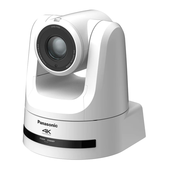
AW‑UE100WP
Model No.
AW‑UE100KP
Model No.
Excerpted Version
4K Integrated Camera
ENGLISH
DVQX2119ZA
Advertisement
Table of Contents

Related Manuals for Panasonic AW-UE100KP


Summary of Contents for Panasonic AW-UE100KP
- Page 1 Antes de instalar y usar este producto, asegúrese de leer “Lea esto primero!” (páginas 4 y 27). ESPAÑOL Si desea obtener más información, visite el sitio web de Panasonic (https://pro-av.panasonic.net/manual/en/index. html) y consulte las instrucciones de funcionamiento y las instrucciones de instalación.
- Page 2 Core™ are trademarks or registered trademarks ® ® AW-UE100WP of Intel Corporation in the United States and other countries. AW-UE100 AW-UE100KP • Adobe and Reader are either registered trademarks or ® ® trademarks of Adobe Systems Incorporated in the United States AW‑RP150G...
-
Page 3: Table Of Contents
Contents Installation Instructions Read this first! ..................4 Connections ..................19 Connecting an NDI|HX compatible switcher ........19 Lea esto primero! .................. 4 Connections with a controller (AW‑RP150) ........20 Installation precautions ................ 5 System example 1 (Serial control) ............. 21 Before installation ................. -
Page 4: Installation Instructions
Panasonic modelo WV‑Q105A. La utilización con otros aparatos puede causar inestabilidad y ADVERTENCIA: posibles lesiones. -
Page 5: Installation Precautions
Installation Instructions Installation precautions Panasonic does not accept any responsibility for accident or damage during installation if procedure in this manual is not followed. To installation personnel Read the “Installation Instructions” thoroughly and then perform the operation correctly and safely. - Page 6 Installation Instructions Installation precautions (continued) Before installation, always disconnect the power Power switch „ „ „ „ This unit does not have a power switch. When the power plug is supplied, the pan, tilt, zoom and focusing operations are When installing, always use the supplied components. performed.
-
Page 7: Before Installation
Installation Instructions Before installation Be sure to configure the switches on the connector panel and bottom of Initialization 2 the unit before installing it. • The unit is reset to the state it was in at the time of purchase. (All Configuring the switches after the unit is installed may prove difficult. -
Page 8: How To Install And Connect The Unit
Installation Instructions How to install and connect the unit Be absolutely sure to read through the “Read this first!” (→ page 4) and “Installation precautions” (→ pages 5 to 6). The procedure given here is for the kind of installation where the unit is suspended from an overhead surface, but the same steps are followed for a stand‑alone installation. - Page 9 Installation Instructions How to install and connect the unit (continued) Mount the mount bracket onto the installation surface. • Use the bracket mounting screws (M4, bind‑head: 10 mm (13/32 inches) long) supplied with the unit. • For proper clamping torque, securely attach the screws using the specified tools. Screw Clamping torque diameter...
- Page 10 Installation Instructions How to install and connect the unit (continued) Mount the unit. • Align the position of the hole for checking the positioning with the status display lamp. • Align the holes on the camera main unit used to insert the bottom panel with the protrusions on the mount bracket used for inserting the camera, push the bracket and camera firmly together, and rotate the main unit by about 15 degrees in the direction of the arrow.
- Page 11 Installation Instructions How to install and connect the unit (continued) Connect the rear panel connectors. Anchor the AC adaptor cable in place using the cable clamp. <NOTE> • Do not connect PoE cable to the RS‑422 port. • For details on recommended products, refer to the catalog or consult your local dealer. •...
- Page 12 Installation Instructions How to install and connect the unit (continued) Attach the cable cover. • Fit the two protrusions on the cable cover into the guides on either side of the camera main unit rear panel. • Using the two screws (M3) supplied with the cable cover, secure the cable cover to the camera main unit. •...
-
Page 13: When Using The Wv-Q105A (Optional Accessory)
Installation Instructions How to install and connect the unit (continued) When using the WV-Q105A (optional accessory) It is recommended that you provide an inspection opening or other such space for access purposes in the area near where the equipment is installed in order to facilitate installation and the wiring connections work. -
Page 14: Removing The Camera
Installation Instructions Removing the camera Turn off the circuit breaker and power. Disconnect the cables. Disconnect the LAN cable, and HDMI cable, etc. Remove the main unit mounting screw used to secure the unit and mount bracket. Push the unit (A). Turn it approximately 15 degrees away from the installed position (B), and remove it (C). Approx. -
Page 15: Stand-Alone Installation (When The Mount Bracket Is Going To Be Used)
Installation Instructions Stand-alone installation (when the mount bracket is going to be used) The same steps are followed as for the kind of installation where the unit is suspended from an overhead surface (→ pages 8 to 11). Check the mounting space. <NOTE>... - Page 16 Installation Instructions Stand-alone installation (when the mount bracket is going to be used) (continued) Check the mounting. Connect the rear panel connectors. <NOTE> • Do not connect PoE cable to the RS‑422 port. • For details on recommended products, refer to the catalog or consult your local dealer. •...
- Page 17 Installation Instructions Stand-alone installation (when the mount bracket is going to be used) (continued) Attach the cable cover. • Fit the two protrusions on the cable cover into the guides on either side of the camera main unit rear panel. •...
-
Page 18: Stand-Alone Installation (When The Mount Bracket Is Not Going To Be Used)
Installation Instructions Stand-alone installation (when the mount bracket is not going to be used) When installing the unit on a desktop Place the unit flat on the surface. <NOTE> • Install the unit in a stable location which will not be susceptible to shaking. If the unit is installed in a location which is susceptible to shaking, this will cause the unit’s images to shake in turn. -
Page 19: Connections
Installation Instructions Connections Connecting an NDI|HX compatible switcher AW-UE100 AW-UE100 Accessory AC adaptor LAN cable Switching hub NDI|HX compatible switcher AV-HLC100 External DC Remote Camera Controller power supply AW-RP150 Monitor Monitor : The AC adaptor provided with the unit is not shown in the above figure. -
Page 20: Connections With A Controller (Aw-Rp150)
Installation Instructions Connections (continued) Connections with a controller (AW-RP150) Example of connection for the function for cropping 4K images to HD images „ „ AW-UE100 AW-UE100 3G SDI OUT Accessory AC adaptor Monitor 12G SDI OUT LAN cable (Straight cable or cross cable) Max. -
Page 21: System Example 1 (Serial Control)
Installation Instructions Connections (continued) System example 1 (Serial control) AW-UE100 AW-UE100 RS-422 connector Accessory AC adaptor Genlock signal generator Pan-tilt head and camera control signal (LAN straight cable) SDI video signal Monitor 1 Monitor 2 Monitor Monitor System TALLY Live Switcher Accessory AV-UHS500 AC adaptor... -
Page 22: System Example 2 (Ip Control)
Installation Instructions Connections (continued) System example 2 (IP control) AW-UE100 AW-UE100 Accessory AC adaptor LAN connector Genlock signal generator LAN cable SDI video signal Monitor 2 Switching hub Monitor 1 LAN cable Monitor Monitor Accessory Live Switcher AC adaptor AV-UHS500 External DC Remote Camera Controller AW-RP150... -
Page 23: System Example 3 (Ip Image Transmission, Poe++)
Installation Instructions Connections (continued) System example 3 (IP image transmission, PoE++) AW-UE100 AW-UE100 LAN connector LAN cable PoE++ compatible switching hub or PoE++ injector LAN cable Mobile terminal Wireless access point Personal computer : The AC adaptor provided with the unit is not shown in the above figure. System example 4 (NDI) AW-UE100 AW-UE100... -
Page 24: Appearance
Installation Instructions Appearance Unit: mm (inch) 84.6 (3-11/32) 169.2 (6-21/32) 170.6 (6-23/32) G/L IN DC IN 12 V AUDIO IN RS-422 LINK 3G SDI OUT 12G SDI OUT IR ID SERVICE Rear panel view... -
Page 25: Operating Instructions
Operation at a voltage other than 120 V AC may require the use of a different AC plug. Please contact either a local or foreign Panasonic authorized service center for assistance in selecting an alternate AC plug. indicates safety information. - Page 26 FCC NOTICE (USA) Supplier’s Declaration of Conformity Model Number: AW-UE100WP/AW-UE100KP Trade Name: Panasonic Responsible Party: Panasonic Corporation of North America Two Riverfront Plaza, Newark, NJ 07102 Support contact: 1‑800‑524‑1448 This device complies with part 15 of the FCC Rules. Operation is subject to the following two conditions: (1) This device may not cause harmful interference, and (2) this device must accept any interference received, including interference that may cause undesired operation.
-
Page 27: Lea Esto Primero
CA diferente. Póngase en contacto con un centro de servicio autorizado por Panasonic, bien sea local o del extranjero, para que le ayude en la selección de una clavija de CA alternativa. -
Page 28: Read This First
SDI, so the unit can be used flexibly in a wide range of situations as a For iPhone, iPad: 4K‑compatible remote camera. Safari • Connection with a Panasonic camera controller is also possible via iPadOS Panasonic's proprietary serial communication format. For Android: Android OS •... -
Page 29: Disclaimer Of Warranty
Panasonic does not accept any responsibility for damage of this type. https://pro‑av.panasonic.net/ • Use the unit in a network secured by a firewall, etc. -
Page 30: Features
The unit can also be used together with the cameras and pan-tilt will restart automatically, and the image will be interrupted. head unit systems currently available from Panasonic Corporation • Use a Category 5e cable or higher when using a PoE++ power so that an existing system can be used to advantage to put supply. -
Page 31: Accessories
Operating Instructions Accessories Check that the following accessories are present and accounted for. • After removing the product from its container, dispose of the power cable cap (if supplied) and packing materials in an appropriate manner. Mount bracket for installation surface Main unit mounting screw (with flat Drop-prevention wire (1) (Hanging/Desktop) (1) -
Page 32: Operating Precautions
Operating Instructions Operating precautions Do not use the unit in oily-smoky or dusty When using the automatic functions „ „ „ „ • In the [Scene] such as the camera menu, the initial settings on places. some items has been set to auto, making it impossible for these Performance may be adversely affected if small particles or other items to be operated manually. - Page 33 This product includes MIT Licensed software. This product includes BSD Licensed software. For details on obtaining the source codes, visit the following website. https://pro‑av.panasonic.net/ However, do not contact Panasonic for questions regarding obtained source codes.
-
Page 34: Wireless Remote Control (Optional Accessory)
Operating Instructions Wireless remote control (optional accessory) This unit can be operated by remote control using a wireless <Layout of wireless remote control signal light-sensing areas> remote control (model number: AW-RM50G) purchased separately. Check out the following points before using the wireless remote <NOTE>... -
Page 35: Parts And Their Functions
Operating Instructions Parts and their functions Camera unit Mount bracket for installation surface (supplied accessory) Mount this bracket onto the installation surface, and then attach the camera main unit to the bracket. Drop-prevention wire This wire is screwed down to the bottom panel of the camera main unit. - Page 36 Operating Instructions Parts and their functions (continued) RS-422 connector <RS-422> G/L IN connector <G/L IN> This RS‑422 connector (RJ‑45) is connected when exercising serial This is the external sync signal input connector. control over the unit from an external device. Use a cable with the This unit supports BBS (Black Burst Sync) and tri‑level following specifications for the connection to this connector.
- Page 37 Operating Instructions Parts and their functions (continued) Initialization 1 DC IN connector <12V > • Reset the user authentication settings and host authentication Connect the AC adaptor supplied with the unit to this connector to settings for network connection. supply the DC 12 V voltage to the unit. (This will delete all the registered user information (IDs/passwords) „...
- Page 38 Operating Instructions Parts and their functions (continued) Output conditions for each video format „ „ Frequency System Format HDMI 12G SDI OUT 3G SDI OUT 2160/59.94p 2160/59.94p 1080/59.94p 2160/59.94p 2160/59.94p 1080/59.94p 1080/59.94p 1080/59.94i 2160/29.97p 2160/29.97p 2160/29.97p 1080/29.97p 2160/29.97p 1080/29.97p 1080/29.97p 1080/59.94p 1080/59.94p 1080/59.94p...
- Page 39 Operating Instructions Parts and their functions (continued) IP video transmission output (multi-channel display) „ „ • When “Streaming mode” is set to “H.265” Settings H.265(1) H.265(2) H.264(1) H.264(2) H.264(3) H.264(4) JPEG(1) JPEG(2) JPEG(3) 1920×1080 1920×1080 1920×1080 1280×720 1280×720 1280×720 Resolution —...
- Page 40 Operating Instructions Parts and their functions (continued) • When “Streaming mode” is set to “H.264” Settings H.265(1) H.265(2) H.264(1) H.264(2) H.264(3) H.264(4) JPEG(1) JPEG(2) JPEG(3) 1920×1080 1920×1080 1920×1080 1280×720 1280×720 1280×720 1280×720 1280×720 Resolution — — 640×360 640×360 640×360 640×360 640×360 640×360 320×180...
- Page 41 Operating Instructions Parts and their functions (continued) • When “Streaming mode” is set to “JPEG (UHD)” Settings H.265(1) H.265(2) H.264(1) H.264(2) H.264(3) H.264(4) JPEG(1) JPEG(2) JPEG(3) 3840×2160 1920×1080 1920×1080 Resolution — — 1280×720 1280×720 1280×720 1280×720 — — 640×360 640×360 640×360 320×180 320×180...
- Page 42 Operating Instructions Parts and their functions (continued) • When “Streaming mode” is set to “RTMP(UHD)” Settings H.265(1) H.265(2) H.264(1) H.264(2) H.264(3) H.264(4) JPEG(1) JPEG(2) JPEG(3) 3840×2160 1920×1080 Resolution — — — — — 1280×720 640×360 640×360 640×360 320×180 320×180 320×180 60fps 30fps 30fps...
- Page 43 Operating Instructions Parts and their functions (continued) • When “Streaming mode” is set to “SRT(H.265 UHD)” Settings H.265(1) H.265(2) H.264(1) H.264(2) H.264(3) H.264(4) JPEG(1) JPEG(2) JPEG(3) 3840×2160 1920×1080 Resolution — — — — — 1280×720 640×360 640×360 640×360 320×180 320×180 320×180 30fps 30fps...
- Page 44 Operating Instructions Parts and their functions (continued) • When “Streaming mode” is set to “SRT(H.264 UHD)” Settings H.265(1) H.265(2) H.264(1) H.264(2) H.264(3) H.264(4) JPEG(1) JPEG(2) JPEG(3) 3840×2160 1920×1080 Resolution — — — — — 1280×720 640×360 640×360 640×360 320×180 320×180 320×180 60fps 30fps...
- Page 45 Operating Instructions Parts and their functions (continued) • When “Streaming mode” is set to “High bandwidth NDI” Settings H.265(1) H.265(2) H.264(1) H.264(2) H.264(3) H.264(4) JPEG(1) JPEG(2) JPEG(3) 1920×1080 1280×720 Resolution — — — — — — — — 640×360 320×180 30fps System 15fps...
-
Page 46: Wireless Remote Control: Aw-Rm50G (Optional Accessory)
Operating Instructions Parts and their functions (continued) MODE button <MODE> Wireless remote control: AW-RM50G (optional This is used to select the video signals which are output from the unit. accessory) Each time it is pressed, the signals are switched between the color bar signals and camera video signals. -
Page 47: Setting The Remote Control Ids
Operating Instructions Parts and their functions (continued) FOCUS button <F> <N> FAST button <FAST> These are used to adjust the lens focus manually when the manual This is used to change the movement speed at which the panning, tilting, setting is established for the lens focus. zooming and focusing operations are performed to the high speed. -
Page 48: Network Settings
[IPv4 downloading it from the following website. overlap] column of the cameras concerned. https://pro‑av.panasonic.net/ • When the [Access Camera] button is clicked, the Live screen of the selected camera is displayed. - Page 49 Operating Instructions Network settings (continued) Network Settings Automatically assigning IP addresses „ „ „ „ Start the Easy IP Setup Software Version.2. Start the Easy IP Setup Software Version.2. Click the [Search] button. Click the [Auto IP] button. <NOTE> Click the camera to be set, and click the [Network •...
-
Page 50: Setting The Initial Account
Operating Instructions Network settings (continued) Setting the initial account Installing the plug-in viewer software To view IP images from the unit on Windows Internet Explorer 11, the Set the initial account. "Network Camera View 4S" plug‑in viewer software (ActiveX ) must be ®... -
Page 51: How To Turn The Power On And Off
Operating Instructions How to turn the power on and off Turning the power on Turning the power off When performing operations from a wireless When performing operations from a wireless remote control remote control Set all the power switches of the units and devices Press one of the <CAM1>... -
Page 52: Troubleshooting
• It may be necessary to upgrade the version of the controller so that controller the controller will support the unit. – – – → For details on upgrading, visit the support page on the following website. https://pro‑av.panasonic.net/ Operating Instructions (PDF) → “Camera menu items” → “Pan/Tilt 1/2 screen” → “Install Position”... - Page 53 Operating Instructions Troubleshooting (continued) Symptom Cause and solution Reference pages • Has a LAN cable of category 5e or above been connected to the LAN pages 21 to 23 connector for IP control <LAN LINK/ACT>? • Is the [LINK] LED of the LAN connector for IP control lit? →...
- Page 54 Operating Instructions Troubleshooting (continued) Symptom Cause and solution Reference pages For Windows: • Press the [F5] key on the keyboard of the personal computer to request that the settings be acquired. – – – For Mac: • Press the [Command] + [R] key on the personal computer's keyboard to request that the settings be acquired.
- Page 55 Operating Instructions Troubleshooting (continued) Symptom Cause and solution Reference pages Operating Instructions (PDF) → “Camera menu items” → “Output 5/5 screen” → “Status Lamp” • Is the [Status Lamp] setting set to [Disable]? Status display lamp does not Operating Instructions (PDF) →...
- Page 56 Operating Instructions Troubleshooting (continued) Video „ „ Symptom Cause and solution Reference pages • Has the unit been connected properly to the other connected devices? pages 19 to 23 • If the system is configured in such a way that the picture is also Operating Instructions (PDF) switched when the unit to be operated is selected, has the correct unit →...
- Page 57 Operating Instructions Troubleshooting (continued) Symptom Cause and solution Reference pages • This is normal operation. 1080/25PsF images appear → In the PsF (Progressive segmented Frame) format, an identical image – – – jerky is captured to fields 1 and 2 in order to output the same image as progressive.
- Page 58 Operating Instructions Troubleshooting (continued) IP images „ „ Symptom Cause and solution Reference pages For Windows: • Is the plug-in viewer software installed? page 50 → Install the plug‑in viewer software. For Windows: • If [Check for newer versions of stored pages] is not set to [Every time I visit the webpage] in the temporary Internet file settings, IP images may not appear in the live screen [Live].
- Page 59 Operating Instructions Troubleshooting (continued) Symptom Cause and solution Reference pages • If the “Network Camera View 4S” plug-in viewer software is deleted in an environment where the “Network Camera View 3” plug-in viewer software is installed, display of H.264 images will become impossible. –...
- Page 60 "This website wants to run the • Select [Allow]. – – – following add-on: 'WebVideo Module' from 'Panasonic System Networks Co., Ltd.'." The following message appears in the information bar. "This website wants to • Select [Install]. When the security warning window appears, click the –...
-
Page 61: Specifications
Operating Instructions Specifications For details on specifications, visit the Panasonic website (https://pro‑av.panasonic.net/manual/en/index.html) and refer to the Operating Instructions. Power requirements: 12 V DC (10.8 V to 13.2 V) (Supplied AC adaptor) 42 V to 57 V DC (PoE++ power supply) Current consumption: 3.0 A (Supplied AC adaptor) -
Page 62: Index
Index Numerics 3G SDI ACTIVE THRU OUT ............... Service switches .................. 3G SDI OUT connector ............... Status display lamp ................12G SDI OUT connector ..............Tally lamp .................... Accessories ..................Tripod screw holes ................AUDIO IN connector ................Ventilation holes .................. Cable clamp .................. - Page 63 MEMO...
- Page 64 Web Site: https://www.panasonic.com © Panasonic Corporation 2020...