
Related Manuals for GE MC-4TX1FXMM-2K


Summary of Contents for GE MC-4TX1FXMM-2K
- Page 1 Security MC-4TX1FXSM-2Km/15Km MC-4TX2FX User Manual P/N 1069180 • REV 1.0 • ISS 22FEB10 firealarmresources.com...
- Page 2 Disclaimer The information in this document is subject to change without notice. GE Security, Inc. (“GE Security”) assumes no responsibility for inaccuracies or omissions and specifically disclaims any liabilities, losses, or risks, personal or otherwise, incurred as a consequence, directly or indirectly, of the use or application of any of the contents of this document.
-
Page 3: Table Of Contents
Content Chapter 1 Introduction 1 Package Contents 2 How to use this Manual 2 Product Features 3 Chapter 2 Installation 5 Product Description 5 Wiring the Fault Alarm Contact 9 Chapter 3 Application 13 Installation Steps 14 Chapter 4 Switch Operation 17 Address Table 17 Learning 17 Forwarding &... - Page 4 MC-4TX1FXSM-2Km/15Km MC-4TX2FX User Manual firealarmresources.com...
-
Page 5: Introduction
Ethernet Switch specifically designed to operate reliably in electrically harsh and climatically demanding environments. The GE Security MC-4TX Series of Industrial Ethernet Switches has an IP-30 metal case. Each of them is equipped with 4 10/100Base-TX Auto-negotiation ports and one or two 100Base-FX optic-fiber SC interfaces. -
Page 6: Package Contents
Chapter 1: Introduction The GE Security MC-4TX Series includes the following models: MC-4TX1FXMM-2Km 4+1 100FX Port Multi-mode Industrial Ethernet Switch – SC/MM 2km MC-4TX1FXSM-15Km 4+1 100FX Port Single mode Industrial Ethernet Switch – SC/SM 15km MC-4TX2FX 4+2 100FX Port Multi-mode Industrial Ethernet Switch – SC/MM 2km... -
Page 7: Product Features
Chapter 1: Introduction Product Features Physical Port Model Name Ports Fiber Optical Interface Copper Optical Mode Distance MC-4TX1FXMM-2Km Mutil-mode 1 x 100Base-FX 4 x 10/100Base-TX MC-4TX1FXSM-15KM Single-mode 15km MC-4TX2FX 2 x 100Base-FX Multi-mode Layer 2 Features • Complies with IEEE 802.3, IEEE 802.3u 10/100Base-TX, 100Base-FX •... - Page 8 Chapter 1: Introduction Product Specifications Model MC-4TX1FXMM-2km MC-4TX2FX M MC-4TX1FXSM-15K Hardware Specification Ports 4 x 10/100Base-TX, Auto-negotiation, Auto-MDI/MDI-X Copper 10Base-T : 2-pair UTP Cat. 3, 4, 5 cable (100meters, max.) Cable 100Base-TX : 2-pair UTP Cat. 5 cable (100meters, max.) Port 1 x 100Base-FX 2 x 100Base-FX...
-
Page 9: Installation
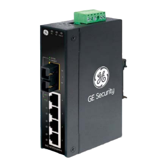
Please read this chapter completely before continuing. Product Description The GE Security MC-4TX1FXMM-2km,/MC-4TX2FX series are 4-Port 10/100Mbps + 1/2 100FX Fiber Port Industrial Fast Ethernet Switches with non-blocking wire-speed performance and a new slim type chassis with an IP 30 metal shape for easy deployment in Heavy Industrial demanding environments. - Page 10 Chapter 2: Installation Switch Front Panel Figure 1 shows the front panel of the Industrial Fast Ethernet Switch. Figure 1: MC-4TX1FXMM and MC-4TX2FX front panels MC-4TX1FXSM-2Km/15Km MC-4TX2FX User Manual firealarmresources.com...
- Page 11 Chapter 2: Installation LED Indicators Color Function Green Lit: indicates the power 1 has power. Green Lit: indicates the power 2 has power. FAULT Green Lit: indicates the either power 1 or power 2 has no power. Green Fiber Lit: indicates the Fiber port is successfully connecting to the Optical network at 100Mbps.
- Page 12 Chapter 2: Installation Wiring the Power Inputs The 6-contact terminal block connector on the top panel of Industrial Fast Ethernet Switch is used for two DC redundant power inputs. Please follow the steps below to insert the power wires. 1. Insert the positive and negative DC power wires into the contacts 1 and 2 for POWER 1, or 5 and 6 for POWER 2.
-
Page 13: Wiring The Fault Alarm Contact
Chapter 2: Installation Wiring the Fault Alarm Contact The fault alarm contacts are in the middle of the terminal block connector as the picture shows below. After inserting the wires, the Industrial Fast Ethernet Switch will detect the fault status of a power failure, or port link failure (available for managed model) and then forms an open circuit. - Page 14 NOTE: In the installation steps below, this Manual uses the GE-DSGH-8 (GE Security’s 8- Port Industrial Gigabit Switch) as an example. The steps for the GE Security Industrial Switch & Industrial Media Converter are the same. Industrial DIN-Rail Mounting The DIN-Rail is screwed on to the Industrial Fast Ethernet Switch when shipped from the factory.
- Page 15 Chapter 2: Installation 3. Check the DIN-Rail is tightly on the track. 4. Please refer to following procedures to remove the Industrial Fast Ethernet Switch from the track. 5. Lightly press the button of DIN-Rail to remove it from the track. MC-4TX1FXSM-2Km/15Km MC-4TX2FX User Manual firealarmresources.com...
- Page 16 Chapter 2: Installation Wall Plate Mounting To install the Industrial Fast Ethernet Switch on the wall, please do the following: 1. Remove the DIN-Rail from the Industrial Fast Ethernet Switch; loosen the screws to remove the DIN-Rail. 2. Place the wall mount plate on the rear panel of the Industrial Fast Ethernet Switch.
-
Page 17: Application
Chapter 3 Application In this section, we describe how to install the Industrial Fast Ethernet Switch. Serial over Ethernet device MC-4TX1FXSM-2Km/15Km MC-4TX2FX User Manual firealarmresources.com... -
Page 18: Installation Steps
Chapter 3: Application Serial Device Server Warehouse ICA-310 Installation Steps 1. Unpack the Industrial Fast Ethernet Switch. 2. Check that the DIN-Rail is screwed onto the Industrial Fast Ethernet Switch. (Please refer to DIN-Rail Mounting section for DIN-Rail installation If the DIN-Rail is not screwed on the Industrial Fast Ethernet Switch.). - Page 19 Chapter 3: Application 5. Prepare the twisted-pair, straight through Category 5 cable for Ethernet connection. 6. Insert one side of Category 5 cables into the Industrial Fast Ethernet Switch Ethernet port (RJ-45 port) and another side of category 5 cables to the network devices' Ethernet port (RJ-45 port), ex: Switch, PC or Server.
- Page 20 Chapter 3: Application MC-4TX1FXSM-2Km/15Km MC-4TX2FX User Manual firealarmresources.com...
-
Page 21: Switch Operation
Chapter 4 Switch Operation Address Table The Industrial Fast Ethernet Switch is implemented with an address table. This address table is composed of many entries. Each entry is used to store the address information of some node in the network, including MAC address, port number, etc. This information comes from the learning process of Industrial Fast Ethernet Switch. -
Page 22: Store-And-Forward
Chapter 4: Switch Operation from address table. But, if the destination address is located at the same port with this packet comes in, then this packet will be filtered. Thereby increasing the network throughput and availability. Store-and-Forward Store-and-Forward is one type of packet-forwarding techniques. A Store-and- Forward Industrial Switch stores the incoming frame in an internal buffer, do the complete error checking before transmission. -
Page 23: Troubleshooting
Chapter 5 Troubleshooting This chapter contains information to help you solve issues. If the Industrial Fast Ethernet Switch is not functioning properly, make sure the Industrial Fast Ethernet Switch was set up according to instructions in this manual. The per port LED is not lit Solution: Check the cable connection of the Industrial Fast Ethernet Switch. - Page 24 Chapter 5: Troubleshooting MC-4TX1FXSM-2Km/15Km MC-4TX2FX User Manual firealarmresources.com...
-
Page 25: Appendix A Network Connection
Appendix A Network Connection Switch's RJ-45 Pin Assignments 10/100Mbps, 10/100Base-TX RJ-45 Connector pin assignment MDI-X Contact Media Dependant Media Dependant Interface Interface -Cross Tx + (transmit) Rx + (receive) Tx - (transmit) Rx - (receive) Rx + (receive) Tx + (transmit) 4, 5 Not used Rx - (receive) - Page 26 Appendix A: Network Connection The standard RJ-45 receptacle/connector There are 8 wires on a standard UTP/STP cable and each wire is color-coded. The following figure shows the pin allocation and color of the straight and crossover cable connection: Straight Cable SIDE 2 SIDE 1 SIDE 1...