
Related Manuals for HP E24mv G4


Summary of Contents for HP E24mv G4
- Page 1 Maintenance and Service Guide E24mv G4 model SUMMARY This guide provides information about spare parts, removal and replacement of parts, diagnostic tests, problem troubleshooting, and more.
- Page 2 AMD is a trademark of Advanced Micro sure to read “Important Safety Information”. Devices, Inc. Bluetooth is a trademark owned by its proprietor and used by HP Inc. under license. NVIDIA is a trademark and/or registered trademark of NVIDIA Corporation in the U.S. and other countries.
-
Page 3: Table Of Contents
Table of Contents 1 Getting started .............................. 2 Important safety information ........................2 Important service information and precautions ..................2 RoHS (2002/95/EC) requirements ......................3 General descriptions ..........................3 Firmware updates ............................ 3 Before returning the repaired product to the customer ................ -
Page 4: Getting Started
Getting started Read this chapter to learn about safety information and where to find additional HP resources. Important safety information Carefully read the cautions and notes within this document to minimize the risk of personal injury to service personnel. The cautions and notes are not exhaustive. Proper service methods are important to the safe, reliable operation of equipment. -
Page 5: Rohs (2002/95/Ec) Requirements
Level 2: Circuit board or standard parts replacement Firmware updates Firmware updates for the monitor are available at support.hp.com. If no firmware is posted, the monitor does not need a firmware update. Before returning the repaired product to the customer Perform an AC leakage current check on exposed metallic parts to be sure the product is safe to operate without the potential of electrical shock. -
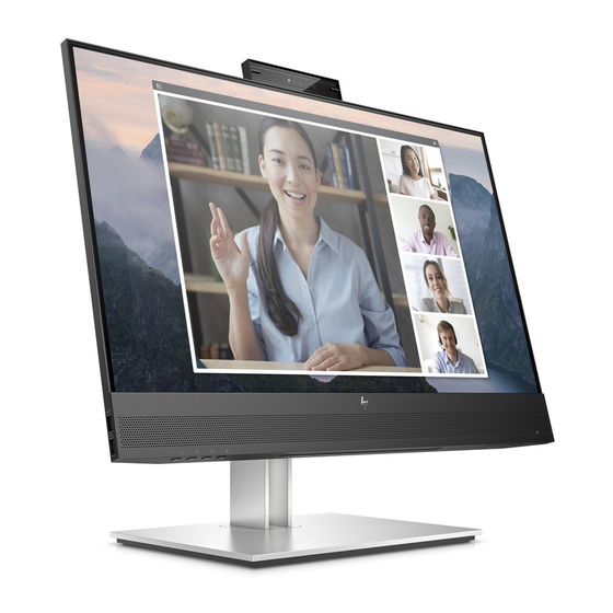
Page 6: Monitor Features
Plug and Play capability, if supported by your operating system Monitor stand ● Removable stand for flexible monitor head mounting solutions ● HP Quick Release 2 device to quickly attach the monitor head to the stand with a simple click, and then 4 ... - Page 7 For safety and regulatory information, refer to the Product Notices provided in your documentation kit. To access the latest user guides or manuals for your product, go to http://www.hp.com/support and follow the instructions to find your product. Then select Manuals.
-
Page 8: Front Components
Front components To identify the components on the front of the monitor, use this illustration and table. Table 1-1: Front components and their descriptions Component Description Tilt levers Allows you to tilt the camera, Camera microphones Allow you to participate in a video conference. Camera light On: The camera is in use. -
Page 9: Rear Components
Safety, and Environmental Notices To access this guide, type HP Documentation in the taskbar search box, and then select HP Documentation. NOTE: When a device is connected to the jack, the speakers are disabled. Power button Turns the monitor on or off. - Page 10 Description Component USB port with HP Sleep and Connects a USB device, provides high-speed data transfer, and charges small (12) Charge devices such as a smartphone, even when the computer is off with OSD Performance mode on. USB port Connects a USB cable to a peripheral device, such as a keyboard, mouse, or (13) USB hard drive, and charges peripheral devices.
-
Page 11: Locating The Serial Number And Product Number
The SPEC label (1) and Barcode label (2) are located on the rear of the monitor. The serial number and product number are located on a Safety label. You may need these numbers when contacting HP about the monitor model. -
Page 12: Illustrated Parts Catalog
Illustrated parts catalog To identify the monitor major components, use this illustration and table. Item Description DECO_BEZEL NA LENS_POWER MIDDLE_FRAME INSULATING SHEET INSULATING SHEET MAINFRAME REAR_COVER SHIELD_USB KEY_FUNCTION KEY_POWER SHIELD_AUDIO ... -
Page 13: How To Order Parts
SCREW -- 6mm(POWER BOARD/MAINFRAME) SCREW -- 10(REAR COVER/MAINFRAME) SCREW 5(Latch/REAR COVER) SCREW 5(KEY BOARD/REAR COVER) How to order parts The HP authorized repair center can purchase the power board from HP. Power board Description HP spare part number Manufacturer part number... - Page 14 Internal and External Power Supplies are available for purchase from the following EU distributor: EET https://www.eetgroup.com/en-eu/ NOTE: HP continually improves and changes product parts. For complete and current information about supported parts for your product, go to https://partsurfer.hp.com/Search.aspx, select your country or region, and then follow the on-screen instructions.
-
Page 15: Removal And Replacement Procedures
Removal and replacement procedures Adherence to these procedures and precautions is essential for proper service. Preparation for disassembly Use this information to properly prepare to disassemble and reassemble the monitor. 1) Read the “Important safety information” and “Important service information and precautions” sections in the “Getting started”... - Page 16 1) Remove four screw from the rear case. 2) Use your fingers to split the left and right sides apart between the middle frame and rear case. 3) Insert the scraper bar tool into the gap between the middle frame and rear case, and then rotate. The hook opens.
- Page 17 5) Disassemble the Speakers. 6) Remove the Webcam module, Key board, Audio Board, Connect board wire and USB board wire from the Rear Cover. 15 ...
- Page 18 7) Remove 2 screws from the bracket. 8) Disassemble 8 screws from the boards. 9) Disassemble all the boards from housing. 10) Disconnect all the wires from the board. 16 ...
-
Page 19: Power Board
Before removing the power board, follow these steps: ▲ Prepare the monitor for disassembly. See Preparation for disassembly on page 13. Remove the power board: 1) The HP E24mv G4 power board connector position is as follows: Warning: After unplugging the power supply, the capacitance is still charged, do not touch and discharge the capacitor. -
Page 20: Connector Repair
Connector repair This procedure includes DisplayPort, HDMI, D-SUB and USB 3.0 connectors. The connectors are on the main board (board part number CBPRNA6HPQ6). The connectors identifiers are as follows: Connector Location DisplayPort CN501 HDMI CN502 D-SUB CN101 USB 3.0 CN106 USB 3.0 CN103 Main Board... - Page 21 USB Board CN1033 CN1032 Before repairing connectors, follow these steps: ▲ Prepare the monitor for disassembly. See Preparation for disassembly on page 13. IMPORTANT: • Repair Condition: Connector repair is only for out of warranty. • Repairing must operate by professional repairers (Note) in repair center, not applicable for end user.
-
Page 22: Dp Connector Cn501
DP connector CN501 Repair the DP connector: 1) Use a soldering iron and a de-soldering pump to remove as much solder as possible from the pin. 2) Use a hot air gun to melt the solder on the pins. 3) Lift the CN501 connector from the circuit board. 4) Place the new component on the circuit board. -
Page 23: D-Sub Connector Cn101
2) Use a hot air gun to melt the solder on the pins. 3) Lift the CN502 connector from the circuit board. 4) Place the new component on the circuit board. Be sure that it matches the footprint. 5) Solder the new component. -
Page 24: Usb 3.0 B Connector Cn106
USB 3.0 B connector CN106 Repair the USB connector: 1) Use a soldering iron and a de-soldering pump to remove as much solder as possible from the pin. 2) Use a hot air gun to melt the solder on the pins. 3) Lift the CN106 connector from the circuit board. -
Page 25: Usb 3.0A Connector Cn1032/Cn1033
2) Use a hot air gun to melt the solder on the pins. 3) Lift the CN103 connector from the circuit board. 4) Place the new component on the circuit board. Be sure that it matches the footprint. 5) Solder the new component. -
Page 26: Audio Connector Cn610
2) Lift the CN1032/CN1033 connector from the circuit board. 3) Place the new component on the circuit board. Be sure that it matches the footprint. 4) Solder the new component. Audio connector CN610 Repair the Audio connector: 1) Use a soldering iron and a de-soldering pump to remove as much solder as possible from the pin. 2) Lift the CN610 connector from the circuit board. -
Page 27: Function Test
Function test After repair, be sure to confirm that all functions are working. Table 4-1: Function test Test item Operating description Tool used HDMI test Confirm whether image displays and sound Computer or DVD plays correctly on the monitor. player DP test Confirm whether image displays and sound... - Page 28 Image appears Brightness setting is too Open the OSD menu, and select Brightness to blurred, adjust the brightness scale as needed. low. indistinct, or too dark. “Check Video Cable” Monitor video cable is Connect the appropriate video signal cable is displayed on the disconnected.
-
Page 29: Index
Index components RC removal, 13 front, 6 rear components, 7 rear, 7 removal connector repair, 18 power board, 17 features, 4 RC, 13 firmware updates, 3 removal and replacement procedures, 13 front components, 6 returning to customer, 3 function test, 25 RoHS (2002/95/EC) requirements, 3 how to order parts, 11...