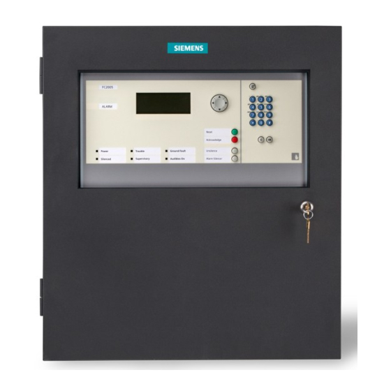
Siemens FC2005 Installation, Operation And Maintenance Manual
Fire alarm control panel
Hide thumbs
Also See for FC2005:
- Programming manual (66 pages) ,
- Installation instruction (3 pages) ,
- System installation instructions (24 pages)

Related Manuals for Siemens FC2005


Summary of Contents for Siemens FC2005
- Page 1 Fire Alarm Control Panel Model FC2005 Installation, Operation and Maintenance Manual A6V10333722_m_en_-- Smart Infrastructure 2021-12-28 firealarmresources.com...
-
Page 2: Table Of Contents
PREFACE ................................3 FCC Part 68 WArning ............................3 INDUSTRY CANADA STATEMENT ........................4 SERVICE REQUIREMENTS ..........................4 DESCRIPTIONS .................................5 FC2005 SYSTEM DESCRIPTION .........................5 Power Supply ..............................6 Signaling Line Circuit (SLC) ..........................6 Notification Appliance Circuits ..........................6 Serial Interface Circuit (UFP) ..........................6 Status Relays ..............................6 Programming Port ...............................6... - Page 3 CONTROL PANEL INSTALLATION ........................24 PARTS SUPPLIED – FC2005 ..........................24 1. FC2005 Enclosure Package ......................... 24 2. FC2005 Main Board Package ........................24 3. FC2005 Configuration Kit Package ......................25 4. FC2005 product documentation ........................25 CONTROL PANEL LOCATION ......................... 26 INSTALLATION ..............................
- Page 4 DACT Wiring ..............................49 PROGRAMMING THE CONTROL PANEL ......................50 KEYPAD PROGRAMMING ..........................50 PC PROGRAMMING ............................50 PROGRAMMING SECURITY ..........................50 MAINTENANCE ..............................51 GENERAL ................................51 QUICK TEST ............................... 52 APPENDIX-A: REFERENCE DATA ........................54 WIRE SELECTION GUIDES ..........................54 Resistance of Solid Copper Wire ........................
- Page 5 firealarmresources.com...
-
Page 6: Introduction
INTRODUCTION CONTROL PANEL LIMITATIONS This control panel may not show an alarm condition without compatible initiating devices (smoke detectors, etc.) and notification devices (horn, strobes, etc.) connected to it. Electrical ratings of the initiation and notification appliances must be compatible with the electrical ratings of the control panel and must be properly interconnected. - Page 7 NOTICE TO USERS, INSTALLERS, AUTHORITIES HAVING JURISDICTION, AND OTHER INVOLVED PARTIES This product incorporates field-programmable software. In order for the product to comply with the requirements in the Standard for Control Units and Accessories for Fire Alarm Systems, UL 864, certain programming features or options must be limited to specific values or not used at all as indicated below.
-
Page 8: Preface
[US: 02XAL00BFCM901]. If requested, this number must be provided to the telephone company. 2. If this equipment FC2005 causes harm to the telephone network, the telephone company will notify you in advance that temporary discontinuance of service may be required. But if advance notice isn’t practical, the telephone company will notify the customer as soon as... -
Page 9: Industry Canada Statement
It is the responsibility of users requiring service to report the need for service to our Company or to one of our authorized agents. Service can be facilitated through our office at: SIEMENS INDUSTRY, INC. – SMART INFRASTRUCTURE DIVISION – FIRE SAFETY 8 FERNWOOD RD., FLORHAM PARK, NJ 07932 +1-800-248-7976... -
Page 10: Descriptions
(NAC), Digital Alarm Communication Transmitter (DACT), four system status relays and a USB programming port. All the components of the FC2005 control panel are mounted in an 18.1" x 16.5" enclosure. The FC2005 has only one electronic main board which integrates most functional parts... -
Page 11: Power Supply
All of the NACs are power limited and support synchronization of listed devices using the Siemens sync protocol. Serial Interface Circuit (UFP) The FC2005 control panel has a Serial Interface Circuit that can connect up to 8 devices, e.g.: remote LCD annunciators, LED driver/tabular annunciator or remote printer module. Status Relays Four relays with dry contacts are provided. -
Page 12: Battery Sets
Battery Sets The FC2005 control panel can only use rechargeable sealed lead-acid batteries for back-up power. The battery charging capacity is 12 Ah for Canada and 12 - 18 Ah for US. Remote Printer Module (FCA2018-U1) The Model FCA2018-U1 is a Universal Fire Protocol module that interfaces to a parallel printer. -
Page 13: Battery Housing (Fh2072-Ua)
For installation in Canada, a separate ULC listed power supply (PAD-4 or PAD-5) must be installed adjacent to the FC2005 or FC901 panel to power the FT2018-U1/R1 or FT2019-U1/R1 annunciator. See Appendix N for PAD-4 Wiring Instruction. -
Page 14: Slc Addressable Devices
SLC ADDRESSABLE DEVICES Smoke Detector The control panel processor sends the sensitivity settings to the detectors and polls the detectors for their status. The detector determines normal, trouble and alarm conditions and communicates the conditions to the control panel. Variable Thresholds - The detectors can be set to operate in various pre-programmed profiles, depending on the environment where the detectors are used. -
Page 15: Programming Slc Devices
The purpose of the PAD-5 main board is to provide remote power for notification devices, and accessory modules, such as door holders. A maximum of 7 PAD-5s, including expander board, can be connected to FC2005 at the same time. Up to 8 Class B, or 4 Class A NACs are supported by one PAD-5 device. -
Page 16: Event History
EVENT HISTORY The control panel includes a non-volatile memory recording 1000 system events. Identified alarm, trouble, supervisory, status and other significant events will be recorded along with the date and time of occurrence. The history event log can be viewed at the main system display by operating menu controls from the panel. -
Page 17: General Design Features
GENERAL DESIGN FEATURES Environmental The FC2005 panels and subassemblies are suitable for use in a dry, indoor or protected location. Power Limiting The AC power connection, battery wiring and four system status relays are not power limited. All other circuits leaving the control panel meet the requirements for power limited circuits when installed in accordance with the National Electrical Code and local requirements. -
Page 18: Regulatory Standards
The FC2005 control panel meets the requirements of industry and government regulatory agencies as noted. Underwriters Laboratories The FC2005 control panel is listed under UL 864 (Tenth Edition) and to be installed in Accordance with the applicable National Fire Protection Association Installation Standard for NFPA 72 and NFPA 2001. -
Page 19: General Specifications
GENERAL SPECIFICATIONS Operating specifications for the FC2005 are as follows: Environmental Operating temperature - 32 – 120 F (0 – 49 C) Relative humidity - Up to 93% @ 90 F (32 C) To be installed in an indoor dry protected environment only... -
Page 20: Status Relays
Status Relays Non-power limited One programmable relay Three non-programmable relays: Trouble, Supervisory, Alarm Contact rating: 2 A, 30 VDC maximum Form C contact Notification Appliance Circuits Power limited Supervised Current Draw Maximum Line Resistance 2.5 A 3.2 Ω 2.0 A 4.0 Ω... -
Page 21: City Tie Circuits
Max. 50 addressable devices City Tie Circuits Supply Input: Voltage: 26 VDC 18 – 28 VDC for battery Current: Max. 0.4 A Supervised Output: City Tie-Output 1 Normal output voltage: 19-28 VDC (open circuit condition) Supervisory current: 1 mA Maximum trip current: 400 mA Maximum coil plus wire resistance: 22.5 Ω... -
Page 22: Dact Circuits
DACT Circuits Power limited Supervised for short or open circuit conditions Compliance to FCC part 68 Support RJ31X connection Compatible Digital Alarm Communication Receiver (DACR) list Installation For installation Manufacturer Model Number Communication Technology Part Number 56044102 Telguard TG-7FS ICOMSLF NAPCO Starlink SLE-LTEVI-FIRE IP/GSM... -
Page 23: Control Panel Operation
CONTROL PANEL OPERATION OPERATION INSTRUCTIONS Standby Condition In normal standby operation, the green AC POWER ON LED should be illuminated and no other indicator operating. The display will show the system label and the current time. Alarm Conditions ALARM When the system detects an alarm condition, the alarm LED activates (ON – flashing) and the local panel buzzer activates in a specific pattern to indicate an alarm condition. -
Page 24: Trouble Conditions
If the FC2005 is configured as “Trouble self-restoring”, the system shall return to the “system normal” status when the trouble condition is restored, unless there are additional events on the system. - Page 25 If the FC2005 is configured as “Supervisory self-restoring”, the system shall return to the “System Normal” status when the supervisory condition is restored unless there are additional events on the system.
-
Page 26: Additional Operating Procedures
ADDITIONAL OPERATING PROCEDURES In addition to the basic fire alarm instructions above, several features are included to facilitate maintenance and increase the versatility of the system. The following are procedures used to initiate these functions. Lamp Test When selected, Lamp Test activates LCD, the buzzer and turns on all the LEDs on the user interface, then back to its previous state. -
Page 27: Fc2005 Operating Instructions
FC2005 OPERATING INSTRUCTIONS Alarm Operation In case of alarm, the Alarm LED flashes, LCD displays alarm conditions and the panel buzzer sounds in a distinct alarm pattern. Local audible and visual signals and remote alarm signals operate. When an alarm occurs, proceed according to the established emergency plan. Assure that all personnel are accounted for and notify the Fire Department to advice of the alarm and/or verify that an automatic signal has been received at the Fire Department. -
Page 28: Fsd901 Operating Instructions
Frame these instructions and mount them near the control panel for operator reference. FSD901 OPERATING INSTRUCTIONS Alarm Operation In case of alarm, the Alarm LED flashes, LCD displays alarm condition and the buzzer sounds. Local audible and visual signals and remote alarm signals operate. When an alarm occurs, proceed according to the established emergency plan. -
Page 29: Control Panel Installation
FC2005 Enclosure Assembly FH901-U2 (Black) / FH902-U2 (Red) FC2005 Main Board Assembly FCM901-U2 / FCM901-L2 Power Supply Assembly FP2011-U1 FC2005 City Tie Module Assembly (optional) FCI2020-U1 FC2005 Configuration Kit (optional) FXS901-U2 FC2005 Spare HW Kit FX901-S1 1. FC2005 Enclosure Package... -
Page 30: Fc2005 Configuration Kit Package
3. FC2005 Configuration Kit Package Description FC2005 Configuration programming disk FC2005 Commissioning cable (FCA3600-A1) 4. FC2005 Product Documentation Product Title Document ID FC2005 System installation instructions A6V11274135 FC2005 Operating instructions (one page) A6V10336901 FC2005 Programming manual A6V10333724 FT2018-U1 Installation instructions... -
Page 31: Control Panel Location
CAUTIONS 1. Remove the printed circuit boards for any procedure that may cause dust, metal shavings, grease (or such matter that may affect the operation of the boards) to get in contact with the units. 2. Disconnect all sources of power prior to installing or removing modules, connecting or disconnecting wiring. - Page 32 Tighten all four bolts securely against the back wall of the backbox. If a semi-flush mount installation is desired, use the Semi-flush Trim for the FC2005. The backbox can be mounted up to 3 1/2 inches into the wall. Place the semi-flush trim around the backbox and affix to the wall with four #10 x 3/4 inch wood screws (provided with trim).
- Page 33 FC2005 Enclosure Mounting Pictures firealarmresources.com...
-
Page 34: Remove Knock-Outs
FC2005 Installation Size 1 61/64” 6-2 3/8” 1 3/16” 1 1/32” 16” 1 7/16” Remove Knock-Outs Prepare the enclosure for electrical wiring by breaking out the appropriate conduit entry points. Segregation is required between power limited and non-power limited conductors. In order to maintain the minimum separation, follow the wire routing illustrated on page 31. -
Page 35: Power Supply Fp2011-U1 Mounting
Power Supply FP2011-U1 Mounting Secure the power supply to the back of enclosure using the four provided #8-32 x 3/8 screws. AC Input terminals must be located at the right side of the enclosure. firealarmresources.com... -
Page 36: Ground Wire Installation
Ground Wire Installation Install one end of the grounding cable on the enclosure back box. Enclosure back box Install the other end of the grounding cable on the enclosure outer door. Enclosure outer door firealarmresources.com... -
Page 37: Battery Installation
Recommended battery size: Length: 5.94 inch, Width: 3.86 inch, Height: 3.7 inch. A separate enclosure must be used if a battery set larger than 12 AH in the FC2005 is required. The FH2072-UA, CAB-BATT or any enclosure UL Listed for Fire Protective Signaling Use may be used. -
Page 38: Optional City Tie Mounting
Optional City Tie Mounting Secure the city tie to the main board using the two provided #4-32 x 3/8 screws. Spacer Detail A 2 #4 screws City tie module Connect the city tie cable between city module and main board. From 1 to 4 From left to right: TP1295,TP1294,TP1293,TP1292... -
Page 39: Main Board Assembly Installation
Main Board Assembly Installation Secure the main board assembly to the enclosure using the four provided #8-32 x 3/8 screws 4 #8 screws Earth Cable Installation Connect the earth cable to the backbox and connector at the upper left corner of the main board. -
Page 40: System Wiring
SYSTEM WIRING Before connecting the field wiring, check the wiring for opens, shorts, grounds and stray voltages. WARNING Damage may result if a high voltage insulation tester is used on wiring while connected to the control panel. Terminate the field wiring to the main board in accordance with the diagrams in System Wiring Section. -
Page 41: Control Panel Wiring Overview
0.25 in. (6.35 mm) or by a nonconductive sleeve or nonconductive barrier from all other conductors. If energy limited cable or equivalent is not used within the FC2005 enclosure, then the following guidelines do not apply. In that case, be sure to follow standard wiring practices. -
Page 42: Wiring Separation
Wiring Separation All high voltage and non-power limited wiring must be kept separate from power limited wiring. A separation of at least 1/4 inch must be maintained with high voltage and non-power limited wiring running in separate conduit openings from power limited wiring. 7 Optional field wire knock-outs Relay-1 Dialer... -
Page 43: Power Supply And Battery Wiring
Battery connector Power input for PCBA For local programming Battery Connections Connect to power operation Supervised supply with power Non-Power Limited cable provided by factory for main board For FC2005 power input. 24 V Battery Set (12 to 18 AH) firealarmresources.com... -
Page 44: Status Relays
Keep All Non-Power Limited Wiring Separate from Power Limited Wiring P2 device Auxiliary power Series Interface City tie and DACT Status Relays circuit output Circuit lease line Power limited Non power limited Wiring terminals located on top of main board Status Relays Four relays with dry contacts are provided at the upper right corner of the main board. - Page 45 The auxiliary power of control panel supervises only the short circuit and ground circuit. The open circuit is not included. To supervise the open circuit, a PAD-5 device power must be used. When using an annunciator with the 50pt. panel, use the non-resettable power supplied from the Fire Alarm Control Panel (FACP).
-
Page 46: Nac Wiring
NAC Wiring Two individual NACs are provided and the polarity shown is when the NAC is activated. Power Limited Supervised Current Draw Maximum Line Resistance 2.5 A 3.2 Ω 2.0 A 4.0 Ω 1.5 A 5.3 Ω 1.0 A 8.0 Ω 0.5 A 16.0 Ω... -
Page 47: Serial Interface Circuit (Ufp)
….. N_AN N_AP N_BN N_BP Serial Interface Circuit (UFP) The serial interface circuit can address up to 8 devices, which includes annunciators and printers. Up to 2 printers can be addressed. Devices on the circuit may be connected up to 4000 feet from the control panel. - Page 48 firealarmresources.com...
-
Page 49: Serial Remote Device Wiring Overview
Serial Remote Device Wiring Overview When connecting devices on the Serial Interface Circuit (UFP), the data wires must be daisy chained and with no T-taps to preserve the integrity of the data. The following diagrams show the proper wiring. Class B / DCLB Annunciator Annunciator Annunciator... -
Page 50: Slc Addressable Device Circuit
SLC Addressable Device Circuit These devices are polled by the control panel every few seconds and input or output functions communicated to determine device status or function. The control panel monitors all device addresses for alarm and trouble conditions. Addressable Device Circuit Class B (DCLB) or Class A (DCLA) or Class X (DCLC) Operation Max. -
Page 51: Slc Addressable Device Wiring Diagrams
Notes: • Siemens SLC Devices: Detectors, Monitor Modules, or Control Modules up to a maximum of 50 devices (include both PORT-A and PORT-B). A maximum of 20 devices recommended per Isolator Module. A maximum of 15 Isolator Modules per addressable device circuit. - Page 52 NOTE Notes: • Siemens SLC Devices: Detectors, Monitor Modules, or Control Modules up to a maximum of 50 devices. A maximum of 20 devices recommended between Isolator Modules. A Maximum of 15 Isolator Modules per addressable device circuit. If more than one HCP is used on a SLC device loop, the loop must be wired Class A (DCLA) or the •...
- Page 53 NOTE Notes: • Siemens SLC Devices: Monitor Modules, or Control Modules up to a maximum of 50 devices. • Only listed Class X (DCLC) devices, models XTRI-R, XTRI-D, XTRI-S, XTRI-M, ILED-XW, ILED-XC, TSM-1X, and PAD-5 can support CLASS X (DCLC) mode. And all these devices must be wiring as isolator module.
-
Page 54: Optional City Tie/Leased Line
Optional City Tie/Leased Line FC2005 provides one city tie or one leased line to connect with local energy and polarity reversal. City tie and Leased line Supervised, Power Limited City tie CT_P Master Box CT_N LL_SP LL_SN Leased line leased line... -
Page 55: Programming The Control Panel
This is the recommended method to program the panel. The Siemens FXS901-U2 software is available to allow programming the control panel by connection to a Personal Computer (PC) with an USB port. This allows ease of operation by preparing the program in advance and downloading to the control panel in a simple, rapid operation. -
Page 56: Maintenance
“MENU” button and select Login item in the View menu, enter the four digit code when prompted and then press “OK”. FC2005 Maintenance is separated into two levels. The user can enter a different password to enter different levels. -
Page 57: Quick Test
To configure the Quick Test parameters, enter L2 user level and navigate to the Quick Test item in the Operate menu. Configure the following parameters prior to starting Quick Test: • Quick Test Time – FC2005 will automatically quit Quick Test mode after the configured time •... - Page 58 This page is left intentionally blank. firealarmresources.com...
-
Page 59: Appendix-A: Reference Data
Total loop resistance – 50 Ohm maximum with 50 devices Total loop capacitance - 0.5 uF max line to line per km and 1.0 uF max line to shield per km Note: • The terminal blocks of Siemens SLC devices are rated for a maximum of 14AWG wire. firealarmresources.com... -
Page 60: Battery Size Calculations
BATTERY SIZE CALCULATIONS System Current Draw Break down System Current Draw Components Standby (A) Alarm (A) Main board 0.1590 0.1864 Auxiliary power City tie module 0.0017 0.0158 firealarmresources.com... -
Page 61: Slc Current Draw Break Down
SLC Current Draw Break down SLC Current Draw Components Standby (A) Alarm (A) HFP-11 0.00140 0.00140 HFPO-11 0.00140 0.00140 HFPT-11 0.00140 0.00140 OOHC941 0.00075 0.00075 OOH941 0.00068 0.00068 OH921 0.00030 0.00030 OP921 0.00030 0.00030 HI921 0.00028 0.00028 FDCIO42 0.00120 0.00120 0.00140 0.00140 HTRI-S... -
Page 62: Battery Size
Battery Size Total Standby Hours of Standby AH for Current Required per NFPA 72 Standby (from above) Standard (4, 24 or 90) Hours Total Alarm 5 Minutes of Alarm AH for Alarm Current Operation per UL (from above) 4 Minutes of Alarm plus 12 hours reduced time annunciation per UL (CO monitoring UL 69.2.5... -
Page 63: Appendix-B: Compatible Devices
APPENDIX-B: COMPATIBLE DEVICES DEVICES FOR ADDRESSABLE DEVICE CIRCUITS x means supported. H-series Point detectors HFPO-11 Photo detector HFP-11 Photo thermal detector HFPT-11 Thermal detector Manual pull station HMS-S Single action manual pull station HMS-D Dual action manual pull station HMS-M Single action metal manual pull station HMS-SA Single action manual pull station... - Page 64 8710 8713 8712 Manual pull station 8700-S Single action manual pull station 8700-D Dual action manual pull station 8700-M Single action metal manual pull station Line modules 8702 Single input interface module 8703 Dual input interface module 8704 Single input interface module with relay 8701 Mini single input interface module 8706...
- Page 65 4) FC2005 support FDOOTC441 CO functionality. CO channel can be configured as automatic alarm event and supervisory event in the detection tree of the FC2005. But it does not comply with UL 2017 standard when the CO channel is configured for an automatic alarm event. It does comply with UL 864.
-
Page 66: Ufp Devices
UFP devices Siemens Cat. No. Description FT2007-U1 LED drive board FT2008-U1 LED annunciator-16 Zone, black FT2008-R1 LED annunciator-16 Zone, red FT2009-U1 LED annunciator-32 Zone, black FT2009-R1 LED annunciator-32 Zone, red FSD901-U2 Floor repeater display, Desigo, black FSD901-R2 Floor repeater display, Desigo, red... -
Page 67: Appendix-C: Troubleshooting
APPENDIX-C: TROUBLESHOOTING DEFINITIONS FOR EVENT HISTORY ENTRIES A. General ENTRY INDICATES Disabled The device has been disabled Ground The device is in ground fault Open The device is in open trouble Short The device is in short trouble Overload The SLC line is overloaded GeneralTrouble The device reports general trouble Unconfig... -
Page 68: System Events
B. System Events ENTRY INDICATES/NOTES Reset Panel reset Silence Silence all silenceable outputs Unsilence Unsilence all silenced outputs Test Start quick test QuitTest Exit quick test Acknowledge Panel events acknowledged Unacknowledge Resound of the trouble/supervisory LogIn User level login LogOut User level logout DACT Bypass The configured DACT module stops working... -
Page 69: Appendix-D: Alarm Verification
APPENDIX-D: ALARM VERIFICATION Smoke detector goes into alarm. (LED on device turns to red) Retard-Reset Period, FACP senses detector in alarm and retards alarm signal. Retard-Reset-Restart Period – FACP reports alarm verification event and the supervisory LED is lit on. In this period. no alarm event is reported on FACP. The duration of this period is adjustable, ranging from 1 s to 60 s. - Page 70 Below devices are compatible with the Alarm verification function: Supported Devices Supported Retard-Reset- Confirm Time Alarm Version (Or Restart Time Range Verification Above) Range Execution OP921 Configurable: Configurable: Panel 1~60 s 60~125 s OH921 OOH941 OOHC941 HFP-11 Depends Configurable: Depends on the Device on the 1~60 s...
-
Page 71: Appendix-E: Application Specific Detection
APPENDIX-E: APPLICATION SPECIFIC DETECTION Application Specific Detection (ASD) allows the system designer to program a detector’s sensitivity, pre-alarm threshold, and other alarm-related parameters using English descriptions of the detector's environment (application). This eliminates the need for detailed knowledge of smoke detector terminology and operation. The designer can set all of the critical detector parameters by simply selecting an application description that closely fits the one where the detector is to be installed. -
Page 72: Appendix-F: Testing/Maintenance
APPENDIX-F: TESTING/MAINTENANCE If the system is connected to the fire department, etc., or actuates an internal system, disarm the appropriate outputs before servicing to prevent actuation. Notify the fire department and personnel at your facility that a System test is being performed so that any alarm sounding can be ignored during the test. -
Page 73: Appendix-G: Lcd, Controls And Indicators
APPENDIX-G: LCD, CONTROLS AND INDICATORS The FC2005 has a buzzer, 7 LEDs, 4 navigational push buttons, 4 push buttons, alphanumeric keypad, 3 menu control buttons (menu, cancel and ok) and a communication port connector. Panel in US Panel in Canada... -
Page 74: Communication Port Connector
Communication Port Connector The communication port is connected to the USB port of the computer that has the FXS901-U2 programming tool. This is used to upload and/or download panel configuration if this method of programming is used. The computer must be disconnected from the panel if not in use. LEDS, Buzzer and Dedicated Push Buttons The LEDs operate as follows: Item... - Page 75 There is no Ground Fault event in system. There are ground fault events in system, but Flashing some of them have not been acknowledged. The LED 7 can only be steady on when any of the following conditions are met: Alarm 1.
- Page 76 FXS901-U2 programming tool. Menu Press Menu button for PMI operation. Four-way button Press A four-way button for menu navigation. firealarmresources.com...
-
Page 77: Lcd Display
LCD Display A 160 by 64 dot LCD display is used to display information such as event types, event amount, event location, user level, releasing timer, etc. A back light is included in the display to assure visibility in dim light. To save power, the back light is only activated during a reported event or on operation of a display control button. - Page 78 LCD display in US The text displays in the below graphic and table is just an example. The actual display corresponds to the actual situation. Line Current text Description Alarm Current event type 01/03 Current event/total events Access level Possible display: V: The event is acknowledged !: The event is unacknowledged Manual Alarm Zone1...
-
Page 79: Appendix-H: Output Features
APPENDIX-H: OUTPUT FEATURES Output Activation- and Deactivation- Delays Each output device has a selection for Activation delay and Deactivation delay when it is installed in the configuration. The Activation delay refers to the delay in which the output will activate after the reception of its activation command. If the Activation delay is set to 0 (default setting), the output immediately activates. -
Page 80: Appendix-I: Pas / Pre-Signal
APPENDIX-I: PAS / PRE-SIGNAL PAS (Positive Alarm Sequence) and Pre-Signal features allow the user to delay the activation of the audibles, strobes and other output devices when an initial alarm is detected. Output can be interlocked by zones. When an initial alarm is detected, all outputs except remote devices (off-premises devices like general relays and city tie) associated with PAS Zone (Zone configured with PAS feature) will be activated immediately. -
Page 81: Pre-Signal
Pre-Signal When an alarm causing device in a Pre-Signal input group is initiated, the alarm condition is reported at the panel. Its associated NACs are not activated until the programmed investigation delay has relapsed or 2 Alarm is initiated anytime during the Pre-Signal delay time (see figure below). -
Page 82: Appendix-J: Dact Information Overview
APPENDIX-J: DACT INFORMATION OVERVIEW The DACT (Digital Alarm Communicator Transmitter) is an optional module for the FC2005 control panel that allows transmission of event information to a remote receiver at a monitoring station using a dial-up modem connection. These events are transmitted in one of the following formats: ◼... - Page 83 To configure an event to be reported to Account 1 and Account 2, set it to Must report on both. If the event needs to be reported to either Account 1 or Account 2, set it to Can report on both. If it has to be reported to Account 1, but only needs to be reported on Account 2 if Account 1 is temporarily out-of-order, set the event to Must Report on Account 1 and Can Report on Account 2.
- Page 84 Scenario 2 – Must/Can Alarm Event is set to Must Report on Account 1 and Can Report on Account 2. Panel fails on Account 1 the first time. Step 1: Panel goes into alarm. Account 1 Step 2: Panel tries to send event to Account 1, but is unsuccessful.
- Page 85 Scenario 3 – Must/Can Alarm Event is set to Must Report on Account 1 and Can Report on Account 2. Panel succeeds on Account 1 the first time. Step 1: Panel goes into alarm. Account 1 Step 2: Panel tries to send event to Account 1 successful.
- Page 86 Scenario 4 – Can/Can Alarm Event is set to Can Report on Account 1 and Account 2. Panel succeeds on Account 2 before Account Step 1: Panel goes into alarm. Account 1 Step 2: Panel tries to send event to Account 1, but is unsuccessful.
-
Page 87: Dact Compatible Alarm Communicators
DACT COMPATIBLE ALARM COMMUNICATORS The FC2005-U2 /-R2 DACT is also compatible with Alarm communicators that utilized different communication technologies (IP and GSM technologies) to connect to compatible Receivers using compatible protocol listed within this documentation. COMPATIBLE ALARM COMMUNICATORS Installation For installation... -
Page 88: Wiring Diagram For Dsc's Tl300Cf And Le4010Cf Connection, Including Trouble Reporting Route
WIRING DIAGRAM FOR DSC’S TL300CF AND LE4010CF CONNECTION, INCLUDING TROUBLE REPORTING ROUTE firealarmresources.com... -
Page 89: Le4010-Cf Configuration
LE4010-CF Configuration (Reference from DSC Installation Manual) firealarmresources.com... -
Page 90: Tl300-Cf Configuration
TL300-CF Configuration (Reference from DSC Installation Manual) firealarmresources.com... -
Page 91: Le4010-Cf & Tl300-Cf Power Supply Wiring Configuration
LE4010-CF & TL300-CF Power Supply Wiring Configuration (Reference from DSC Installation Manual) The ACT shall be connected to Input 1 of the transmitter and transmission delay is to be configured via CONNECT 24. The LBT and TEST shall be connected to FACP’s trouble inputs. The outputs are active low (switched to ground) and shall be connected via listed supervision relay (suggested model: DSC, RM-2 or RM1C). -
Page 92: Appendix-K: Drift Compensation
APPENDIX-K: DRIFT COMPENSATION The H-Series optical detector cannot implement drift compensation on its own. Drift compensation is the panel’s responsibility. While the system is running, the detector sends its chamber real-time values to the panel periodically and does not do compensation by itself. For the first hour after a panel startup, the panel will check the detector chamber values every 10 minutes. -
Page 93: Appendix-L: Releasing Operation
APPENDIX-L: RELEASING OPERATION Configure: • Set up a countdown time for the releasing operation to start when the releasing control condition is satisfied. • Set up the activation time for the NAC/Output channel: ReleaseSync: operate simultaneously with the releasing channel. Immediately: operate once the releasing control condition is satisfied. - Page 94 Releasing indication configuration in Canada For Canadian applications, LEDs on FT2018 or FT2019 annunciator shall be configured to indicate pre-discharge, discharge, abort in alarm condition and “invalid abort” trouble in normal standby condition. Following is an example of configuration: Preconditions: Releasing control configuration •...
- Page 95 Release Release circuit Yellow steady Releasing circuit trouble Trouble trouble Releasing circuit is normal Indication Invalid abort Yellow steady Abort switch activation normal trouble standby condition No invalid abort switch activation firealarmresources.com...
-
Page 96: Appendix-M: Glossary
APPENDIX-M: GLOSSARY AC Power Fail. Refers to a condition in which AC power loss is detected by the system. Alarm Signal. A signal indicating an emergency requiring immediate action, such as an alarm for fire from a manual station, a waterflow alarm, or an automatic smoke detector. Signal Silence Inhibit. - Page 97 Programming Tool. Refers to an external proprietary software package that allows the user to program the panel (FXS901-U2 for the FC2005 panel). Quick Test. A term pertaining to the test mode of the system, that automatically resets after a service technician tests initiating devices.
- Page 98 Trouble Signal. An audible signal indicating trouble of any nature, such as a circuit break or ground, occurring in the device or wiring associated with a fire alarm signal. Waterflow Switch. An assembly approved for service and so constructed and installed that any flow of water from a sprinkler system equal to or greater than that from a single automatic sprinkler head will result in activation of this switch and subsequent indication of an alarm condition.
-
Page 99: Appendix-N: Pad-4 Wiring Instruction
APPENDIX-N: PAD-4 WIRING INSTRUCTION Placeholder for PAD-4 to FC360 wiring instruction so the PAD-4 is able to report troubles back to the FC360. firealarmresources.com... - Page 100 APPENDIX-O: ISOLATOR SUPPORT Isolator support feature allows a device with an isolator to report alarms as well when a short circuit or open circuit happens on the device. The wiring of the device with an isolator and the setting of its corresponding “Isolator Support” checkbox on FXS901 tool should be consistent, otherwise, the system reports trouble.
- Page 101 Issued by: © Beijing Siemens Cerberus Electronics Ltd., 2016 Beijing Siemens Cerberus Electronics Ltd. Technical specifications and availability subject to change without notice. No.1, Fengzhi East Road, Xibeiwang Haidian District, 100094 BEIJING, China Tel. +86 10 64768806 Document no. A6V10333722_m_en_-- Manual FC2005 firealarmresources.com...