Table of Contents
Advertisement
Quick Links
SAFETY PRECAUTION FOR SERVICE MANUAL ........................................................................................................... 2
VOLTAGE SELECTION ..................................................................................................................................................... 2
AC POWER SUPPLY CORD AND AC PLUG ADAPTOR ................................................................................................. 3
SPECIFICATIONS ............................................................................................................................................................. 3
NAMES OF PARTS ........................................................................................................................................................... 4
OPERATION MANUAL ...................................................................................................................................................... 6
DISASSEMBLY .................................................................................................................................................................. 9
REMOVING AND REINSTALLING THE MAIN PARTS ................................................................................................... 12
ADJUSTMENT ................................................................................................................................................................. 13
BLOCK DIAGRAM ........................................................................................................................................................... 17
SCHEMATIC DIAGRAM / WIRING SIDE OF P.W.BOARD .............................................................................................. 20
VOLTAGE ........................................................................................................................................................................ 38
NOTES ON SCHEMATIC DIAGRAM .............................................................................................................................. 39
TYPES OF TRANSISTOR AND LED ................................................................................................................................ 39
WAVEFORMS OF CD CIRCUIT ...................................................................................................................................... 40
TROUBLESHOOTING ..................................................................................................................................................... 41
FUNCTION TABLE OF IC ................................................................................................................................................ 45
FL DISPLAY ...................................................................................................................................................................... 53
REPLACEMENT PARTS LIST/EXPLODED VIEW
SERVICE MANUAL
MODEL
CONTENTS
SHARP CORPORATION
- 1 -
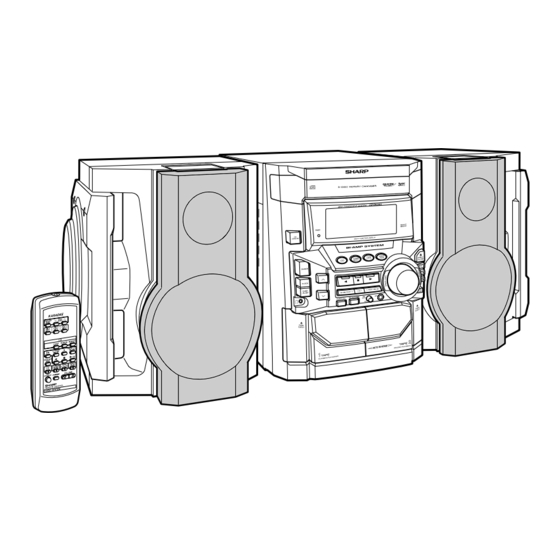
MINI COMPONENT SYSTEM
CD-BK300W
CD-BK300W Mini Component System consisting of
CD-BK300W (main unit) and CP-BK300 (speaker system).
• In the interests of user-safety the set should be restored to its
original condition and only parts identical to those specified be
used.
This document has been published to be used
for after sales service only.
The contents are subject to change without notice.
CD-BK300W
No. S5133CDBK300W
Page
Advertisement
Table of Contents

Related Manuals for Sharp CD-BK300W


Summary of Contents for Sharp CD-BK300W
-
Page 1: Table Of Contents
MINI COMPONENT SYSTEM CD-BK300W MODEL CD-BK300W Mini Component System consisting of CD-BK300W (main unit) and CP-BK300 (speaker system). • In the interests of user-safety the set should be restored to its original condition and only parts identical to those specified be used. -
Page 2: Safety Precaution For Service Manual
CD-BK300W SAFETY PRECAUTION FOR SERVICE MANUAL WARNINGS THE AEL (ACCESSIBLE EMISSION LEVEL) OF THE LASER POWER OUTPUT IS LESS THAN CLASS 1 BUT THE LASER COMPONENT IS CAPABLE OF EMITTING RADIATION EXCEEDING THE LIMIT FOR CLASS 1. THEREFORE IT IS IMPORTANT THAT THE FOLLOWING PRECAUTIONS ARE OBSERVED DURING SERVICING TO PROTECT YOUR EYES AGAINST EXPOSURE TO THE LASER BEAM. -
Page 3: Ac Power Supply Cord And Ac Plug Adaptor
CD-BK300W AC POWER SUPPLY CORD AND AC PLUG ADAPTOR QACCA0003AW00 QACCL0005AW00 QACCZ0007AW00 QACCB0011AW00 QACCE0010AW00 QPLGA0004AWZZ QPLGA0003AWZZ QACCJ0007AW00 FOR A COMPLETE DESCRIPTION OF THE OPERATION OF THIS UNIT, PLEASE REFER TO THE OPERATION MANUAL. SPECIFICATIONS CD player CD-BK300W General Type 3-disc multi-play compact disc player... -
Page 4: Names Of Parts
CD-BK300W NAMES OF PARTS CD-BK300W Front panel 1. Disc Tray 2. Timer Set Indicator 3. On/Stand-by Button 4. Tape 2 Cassette Compartment 5. Tape 1 Cassette Compartment 6. Equalizer Mode Select Button 7. Volume Control 8. Extra Bass/Demo Mode Button 9. - Page 5 CD-BK300W CD-BK300W Rear panel 1. FM 75 Ohms Aerial Terminal 2. FM Aerial Earth Terminal 3. AM Loop Aerial Socket 4. Span Selector Switch 5. Video/Auxiliary (Audio Signal) Input Sockets 6. Speaker Terminals 7. AC Power Lead 8. AC Voltage Selector Remote control 1.
-
Page 6: Operation Manual
CD-BK300W CP-BK300 1. Subwoofer 2. Bass Reflex Duct 3. Tweeter 4. Woofer 5. Speaker wire for SUBWOOFER terminals 6. Speaker wire for MAIN terminals OPERATION MANUAL System Connections Setting the AC voltage selector Setting the FM/AM span selector Check the setting of the AC voltage selector located on the rear panel before plug- ging the unit into an AC socket. - Page 7 CD-BK300W Setting the Clock Press the TUNING/TIME ( or ) button to adjust the hour and then press the MEMORY/SET button. Press the TUNING/TIME ( ) button once to advance the time by 1 hour. Hold it down to advance continuously.
- Page 8 Cassette deck technician. If something is wrong with this product, check the following before calling your autho- Symptom Possible cause rised SHARP dealer or service centre. Cannot record. Is the erase-prevention tab removed? General Cannot record tracks with proper Is it a normal tape? (You cannot record on sound quality.
-
Page 9: Disassembly
CD-BK300W DISASSEMBLY CD-BK300W Caution on Disassembly Follow the below-mentioned notes when disassembling (A1) x 2 Top Cabinet the unit and reassembling it, to keep it safe and ensure ø3 x 12mm excellent performance: 1. Take cassette tape and compact disc out of the unit. - Page 10 CD-BK300W (H1) x 1 (H3) x 1 Clamp Lever Display PWB (L1) x 1 ø3 x 10mm Mic PWB (H2) x 13 CD Player Unit ø3 x 10mm (Top View) Tape Front Panel Mechanism Cam Gear Rib Open (J1) x 5 ø3 x 10mm...
- Page 11 CD-BK300W (Q2) x 3 Mechanism (P1) x 1 Slide CD Servo ø3 x 8mm Chassis (P3) x 2 (Q1) x 1 (Q1) x 1 (P2) x 2 (P3) x 2 Figure 11-1 Figure 11-2 CP-BK300 STEP REMOVAL PROCEDURE FIGURE Side Panel/ 1.
-
Page 12: Removing And Reinstalling The Main Parts
CD-BK300W REMOVING AND REINSTALLING THE MAIN PARTS TAPE 2 TAPE MECHANISM SECTION Clutch Ass'y Perform steps 1 to 7 and 9 of the disassembly method to Record/Playback remove the tape mechanism. Head How to remove the record/playback and erase heads (TAPE 2) (See Fig. 12-1) Erase Head 1. -
Page 13: Adjustment
CD-BK300W CD MECHANISM SECTION Loading Motor Perform steps 1, 2, 3, 12, 13, 14 and 15 of the disassembly Loading Slide method to remove the CD mechanism. Motor PWB Chassis How to remove the loading motor (See Fig. 13-1) (A1) x 1 (A1) x 2 1. - Page 14 CD-BK300W • FM RF TUNER SECTION Signal generator: 1 kHz, 40 kHz dev., FM modulated fL: Low-range frequency fH: High-range frequency Test Stage Frequency Frequency Setting/ Instrument • AM IF/RF Display Adjusting Connection Point Signal generator: 400 Hz, 30%, AM modulated FM Band —...
- Page 15 CD-BK300W TEST MODE • Setting the test mode Any one of test mode can be set by pressing several keys as follows. <X-BASS> + <CD> + <POWER> TEST:CD operation test Function:-CD test mode. -Enter test mode. T E S T IL isn't done OPEN/CLOSE operation is using manual.
- Page 16 CD-BK300W Standard Specification of Stereo System Error Message Display Contents Error Contents DISPLAY Notes Output while Device Protection Operation 'PROTECT' 00: While in Protect Circuit Operate 01: Over Current Detection 02: DC Detection TAPE Mechanism Error 'ER-TA**' 00: Tape Mechanism Error...
-
Page 17: Block Diagram
CD-BK300W DISC CLAMP NUMBER OPEN/ CLOSE T/T UP DOWN LOADING TO MAIN SECTION TO DISPLAY SECTION 43 44 LC78645E CD SERVO XOUT 17 25 CONT5 SLDO SPDO VCC1 M63001FP VCC4 FOCUS/TRACKING/ VCC2 SPIN/SLED +3.3V DRIVER VCC3 26 27 CONSTANT LASER... - Page 18 CD-BK300W ANTENNA FM IF 10.7MHz CNP301 IC301 CF303 T302 TA7358AP BF301 CF351 X351 FM FRONT END 450kHz B.P.F 456kHz T351 CF352 AM IF 17 13 IC303 AM MIX AM IF FM+B MO/ST LA1832S L312 T301 FM IFDET. FM MPX./ FM/AM...
- Page 19 CD-BK300W FL701 FL DISPLAY JOG701 15 20 35 53 56 57 58 Q701-Q703 Q710-Q712 RX701 REMOTE SENSOR SW701-SW703 SW709-SW717 VLOAD SW722-SW734 IC701(1/2) IC704 BU2092F IX0427AW AVDD INPUT/OUTPUT SYSTEM MICROCOMPUTER EXPANDER IC704 9 10 11 12 13 15 16 17 20 21 22 23...
-
Page 20: Schematic Diagram / Wiring Side Of P.w.board
CD-BK300W PICKUP UNIT CD SERVO PWB-C CD SIGNAL VREF VREF LASER DRIVER 0.047(ML) CNP1 100P 0.0047 (CH) 10/50 100/10 TR– TR– 0.22/50 FO– FO– 100P FO– TR– 0.01 100/10 CD MOTOR PWB-G MUTE SPINDLE SPIN MOTOR SP– – SLED SLIDE SL–... - Page 21 CD-BK300W R38 1K 100P R37 1K 100P R36 1K 100P R35 1K R34 1K 100P R33 1K R32 1K 100P 0.022 CNS703 2.2K FROM CD RES DISPLAY PWB P25 10-B CLAMP SW 47(ML) 2.2K 80 79 78 77 76 75 74 73 72 71 70 69 68 67 66 65 64 63 62 61...
- Page 22 CD-BK300W CNS11 R-CH A_GND L-CH R601 IC601 LC75341 CD_GND R602 IC601 C604 CD_+B LC75341 0.022 R603 AUDIO PROCESSOR A_+B BI11 VREF INTERFACE C602 10/5 22/50 LOUT ROUT C609 C610 C608 0.1(ML) 0.1(ML) 0.1(ML) C607 RBASS R607 C613 LBASS 0.1(ML) R605...
- Page 23 CD-BK300W MAIN PWB-A (1/2) FM SIGNAL PLAYBACK SIGNAL R601 RECORD SIGNAL R602 CD SIGNAL R603 VIDEO SIGNAL MIC SIGNAL R633 C614 L-ch C602 10/50 C631 22/50 R631 390P 3.3K C610 JK601 C608 0.1(ML) VIDEO/AUX 0.1(ML) R632 C632 3.3K 390P R606...
- Page 24 CD-BK300W DISPLAY PWB-B1 FL701 FL DISPLAY R701 R704 R716 100K 100K 100K Q701 Q702 Q703 KTC3199 GR C715 KTC3199 GR KTC3199 GR 22/50 C714 47/50 VLOAD R727 R728 P19/DIST0 R794 P20/DIST1 DT704 P21/DIST2 DS1SS133 P22/DIST3 NO USE NO USE NO USE...
- Page 25 CD-BK300W CD SERVO PWB P21 12-B CNP8 CNS703 C722 47/50 BI703 C726 220/10 R773 C725 -20dBATT 0.022 CNP701 R774 DSA_STB R775 T-BIAS R776 MIC_IN T-T1/T2 R777 KARAOKE LATCH REC/PLAY R778 SPAN RES OUT R779 P_IN R780 M_+12 V R781 REC/PLAY...
- Page 26 CD-BK300W IC902 POWER AMP. (2Ch) STK4029S – 10 11 C907 220P R995 R902 0.22(2W) C906 C926 C910 C903 220P C904 220P 100/50 C928 100/ 100/50 C902 R918 C901 10/50 10/50 R901 R908 R904 R976 C911 R912 47/50 0.1(1W) R928 R932...
- Page 27 CD-BK300W IC901 STK40271 (2Ch) POWER AMP. – C927 220P R986 0.22(2W) R926 C926 C922 220P C928 100/50 C923 C920 C921 AMP PWB-D2 10/50 10/50 100/50 R924 C931 R934 1/50 0.1(1W) R928 R932 R933 0.1(1W) R930 R938 C924 D906 Q908 R940 0.022...
- Page 28 CD-BK300W SO302 FM ANTENNA TERMINAL CNP301 MAIN PWB-A (2/2) R326 BF301 C303 C314 D305 DS1SS133 B.P.F. 10P(CH) 0.0047 C308 FM SIGNAL FM RF 4.7P(UJ) L312 C304 0.01 C315 AM SIGNAL R311 0.0047 100K C305 C316 4.7P 0.022 (CH) R313 VD302...
- Page 29 CD-BK300W MIC PWB-H MIC SIGNAL CK48 220P RK47 CK41 RK46 8.2K CK53 100/16 47/50 ICK1 DS1SS133 CK50 M65856SP CK46 100P MIC AMP. 2.2/50 RK45 RK11 6.8K DATA MICSW DS1SS133 CK35 0.01 CK51 RK10 MCLKCONT CLOCK RK49 1/50 CK34 VACL LATCH...
- Page 30 CD-BK300W TO CD SERVO PWB TO MIC P36 5-A P29 1 CNP7 CNS11 CNS11 1 2 3 4 5 1 2 3 4 5 6 MAIN PWB-A R374 R372 C384 R378 X352 IC302 R388 R359 C382 R376 R360 C381 R379...
- Page 31 CD-BK300W TO DISPLAY PWB TO MIC PWB P33 11-A P29 12-G CNP701 CNP7 FC701 3 4 5 6 8 9 10 R114 Q128 BI102 CNS102 Q109 Q110 R113 R160 Q111 R167 L103 R168 R166 R115 C150 2 4 6 8 10 12 14 16 18...
- Page 32 CD-BK300W 1 2 3 6 7 8 9 10 11 12 13 14 15 16 TO CD R702 SERVO PWB P36 4-A C722 R705 Q702 R719 CNP8 R796 Q703 Q701 CNS703 C725 Q709 RX701 R781 C723 C728 D718 R774 C724...
- Page 33 CD-BK300W TO MAIN PWB P31 8-A CNP601 FC701 25 26 27 28 29 30 31 32 33 34 35 36 37 38 39 40 41 42 43 44 56 57 58 R727 FL701 R728 25 27 24 26 CNP701 85 75...
- Page 34 CD-BK300W TRANSFORMER PWB-D3 SW801 VOLTAGE SELECTOR COLOR TABLE 230-240 V BROWN 220 V RD(R) ORANGE 110 V 127 V YELLOW LG902 GREEN BLUE VIOLET GRAY AC POWER SUPPLY CORD WH(W ) WHITE AC 110/127/220/ 230-240 V, 50/60 Hz BLACK LG901...
- Page 35 CD-BK300W SO902 SPEAKER TERMINAL L-CH L-CH R-CH R-CH (HI) (LOW) (LOW) (HI) AMP. PWB-D2 L902 L903 L905 L904 CNS803 R951 CNP804 R950 Q910 M901 FAN MOTOR R949 B C E R948 R980 R979 CNS804 M902 FAN MOTOR C960 C910 R960...
- Page 36 CD-BK300W P30 6-A P32 1-B FROM MAIN PWB FROM DISPLAY PWB CD SERVO PWB-C CNS11 CNS703 1 2 3 4 5 6 7 8 9 1 2 3 4 5 6 CNP7 CNP5 CNP8 61 60 65 55 30 35...
- Page 37 CD-BK300W P32 4-G TAPE MECHANISM TO DISPLAY PWB ASSEMBLY CNS702 FC702 TAPE MECHANISM PWB-F SOLENOID SOLENOID TAPE MOTOR TAPE 1 PLAYBACK HEAD TAPE 2 RECORD/PLAYBACK/ERASE HEAD 654321 CNS102 P32 12-C CNP101 TO MAIN PWB P31 11-D TO MAIN PWB COLOR TABLE...
-
Page 38: Voltage
CD-BK300W VOLTAGE IC101 IC601 IC701 NO. VOLTAGE NO. VOLTAGE NO. VOLTAGE NO. VOLTAGE NO. VOLTAGE NO. VOLTAGE 3.7 V 2.0 V 1.6 V 4.7 V 3.7 V 12.6 V 1.0 V 12.6 V 1.6 V 0.5 V 12.6 V 1.8 V 2.0 V... -
Page 39: Notes On Schematic Diagram
CD-BK300W NOTES ON SCHEMATIC DIAGRAM • Resistor: • The indicated voltage in each section is the one measured To differentiate the units of resistors, such symbol as K and by Digital Multimeter between such a section and the chas- M are used: the symbol K means 1000 ohm and the symbol sis with no signal given. -
Page 40: Waveforms Of Cd Circuit
CD-BK300W WAVEFORMS OF CD CIRCUIT Stopped Stopped 1999/04/07 09:51:15 CH1=200 mV CH2=500 mV 500 ms/div CH1=500 mV CH3=500 mV 500 ms/div DC 10:1 DC 10:1 (500 ms/div) DC 10:1 DC 10:1 (500 ms/div) NORM:20 kS/s NORM:20 kS/s IC1 21 IC1 21... -
Page 41: Troubleshooting
CD-BK300W TROUBLE SHOOTING When the CD does not function When the CD section does not operate when the objective lens of the optical pickup is dirty, this section may not operate. Clean the objective lens, and check the playback operation. When this section does not operate even after the above step is taken, check the following items. - Page 42 CD-BK300W Stopped (1) Focus-HF system check. CH1=500 mV CH3=500 mV 500 ms/div DC 10:1 DC 10:1 (500 ms/div) NORM:20 kS/s Although a CD is inserted and the cover is closed, "NO DISC" is displayed. Press the OPEN/CLOSE switch (SW1) without inserting a disc, and try starting the playback operation.
- Page 43 CD-BK300W (2) Tracking system check. Check the TE waveform at pin 15 on IC1. The tracking servo is not activated. If the waveform shown in Figure 43-1 appears and soon after Check the peripheral circuits at pins 14, 15 and 20 on IC1, and NO DISC appears ? CNS1A/B.
- Page 44 CD-BK300W (4) PLL system check. Stopped 1999/04/05 17:33:17 CH1=500 mV CH3=1 V CH4=1 V 500 ms/div DC 10:1 DC 10:1 DC 10:1 (500 ms/div) NORM:20 kS/s When a disc is loaded, start play operation. PDO1 The HF waveform is normal, but the TOC data cannot be PDO2 read.
-
Page 45: Function Table Of Ic
CD-BK300W FUNCTION TABLE OF IC IC1 VHiLC78645E-1: CD Servo (LC78645E) (1/2) Terminal Name Input/Output Setting in Reset Pin No. Function SLCO Output — Control output. For slice level SLCIST Input — Resistor connection terminal for SLCO output current setting. control. - Page 46 CD-BK300W IC1 VHiLC78645E-1: CD Servo (LC78645E) (2/2) Terminal Name Input/Output Setting in Reset Function Pin No. RVSS — — GND for Right channel. Must be connected to 0 V. Right channel RCHO Output LVDD /2 Right channel output. D/A converter...
- Page 47 CD-BK300W IC1 VHiLC78645E-1: CD Servo (LC78645E) 75 74 72 71 69 68 66 65 63 62 SLC0 DATA SLCIST DATACK EFMIN LRSY ASDFIN RFVDD ASDACK RFVSS ASLRCK FIN1 16MOUT FIN2 EFLG TIN1 TIN2 XVSS LC78645E VREF FSX/16MIN REFI XOUT XVDD...
- Page 48 CD-BK300W IC701 RH-iX0427AWZZ: System Microcomputer (IX0427AW) (1/2) Pin No. Port Name Terminal Name Input/Output Function Input (+) POWER SUPPLY. -20 dB ATT Output -20 dB ATTENUATOR. NO USE Output DSA_STB Input/Output DSA STRUBE T_BIAS Output TAPE RECORD BIAS. T_T1/T2 Output TAPE T1/T2 CHANGE.
- Page 49 CD-BK300W IC701 RH-iX0427AWZZ: System Microcomputer (IX0427AW) (2/2) Pin No. Port Name Terminal Name Input/Output Function P124 T 1 RUN Input TAPE 1 RUN PULSE INPUT. P123 T 2 RUN Input TAPE 2 RUN PULSE INPUT. P122 CD CLAMP SW Input CD CHANGER CLAMP SWITCH.
- Page 50 CD-BK300W IC601 VHiLC75341/-1: Audio Processor (LC75341) ROUT LOUT LBASS RBASS 0.1uF 0.1uF LTRE RTRE LSEL0 RSEL0 R1 R2 24 23 22 21 20 19 18 17 16 15 14 13 LC75341 10 11 12 Figure 50 BLOCK DIAGRAM OF IC...
- Page 51 CD-BK300W ICK1 VHiM65856SP-1: Mic Amp. (M65856SP) (1/2) Pin No. Port Name Input/Output Function MIC SW Input Microphone SW L: MIC OFF, H: MIC ON MCLKCONT — Clock Control. Controls built-in clock generation circuit with external R. VALC — ALC operating voltage setting terminal.
- Page 52 CD-BK300W ICK1 VHiM65856SP-1: Mic Amp. (M65856SP) (2/2) Pin No. Port Name Input/Output Function KEYCONIN Input Monaural input for external KEYCONTROL IC. Input/Output interface terminal for external KEYCONTROL IC. SOURCEOUT Output Monaural input for external KEYCONTROL IC. Input/Output interface terminal for external KEYCONTROL IC.
-
Page 53: Fl Display
CD-BK300W FL DISPLAY FL701 VVKBJ11LM02T1: FL Display B7 B6 B5 B4 B3 B4 B5 B6 B7 (Hiper) (Lower) – 53 –... - Page 54 CD-BK300W –– MEMO –– – 54 –...
- Page 55 PARTS GUIDE MINI COMPONENT SYSTEM CD-BK300W MODEL CD-BK300W Mini Component System consisting of CD-BK300W (main unit) and CP-BK300 (speaker system). “HOW TO ORDER REPLACEMENT PARTS” To have your order filled promptly and correctly, please furnish the For U.S.A. only following information.
- Page 56 CD-BK300W PRICE PRICE PARTS CODE DESCRIPTION PARTS CODE DESCRIPTION RANK RANK ZD351 VHEDZ5R1BSB-1 AC Zener,5.1V,DZ5.1BSB CD-BK300W ZD701 VHEMTZJ6R2C-1 AC Zener,6.2V,MTZJ6.2C ZD801 VHEDZ300BSB-1 AB Zener,30V,DZ300BSB INTEGRATED CIRCUITS ZD802 VHEDZ6R2BSA-1 AB Zener,6.2V,DZ6.2BSA ZD803 VHEDZ130BSC-1 AB Zener,13V,DZ13BSC ZD804 VHEDZ110BSB-1 AB Zener,11V,DZ11BSB VHILC78645E-1 AY CD Servo,LC78645E...
- Page 57 CD-BK300W PRICE PRICE PARTS CODE DESCRIPTION PARTS CODE DESCRIPTION RANK RANK AC 220 µF,6.3V,Electrolytic AA 0.001 µF,50V VCEAZA0JW227M J C392 VCKYMN1HB102K J AB 100 µF,10V,Electrolytic AB 1 µF,50V,Electrolytic VCEAZA1AW107M J C393 VCEAZA1HW105M J AA 0.01 µF,16V AB 47 µF,25V,Electrolytic VCTYMN1CY103N J...
- Page 58 CD-BK300W PRICE PRICE PARTS CODE DESCRIPTION PARTS CODE DESCRIPTION RANK RANK AB 0.22 µF,50V,Polyester C945,946 VCFYDA1HA224J VRD-ST2CD123J AA 12 kohms,1/6W C947,948 VCCSPA1HL101J AA 100 pF,50V R45,46 VRD-MN2BD471J AA 470 ohms,1/8W AA 0.022 µF,50V C949,950 VCKZPA1HF223Z VRD-MN2BD101J AA 100 ohm,1/8W AB 10 µF,50V,Electrolytic...
- Page 59 CD-BK300W PRICE PRICE PARTS CODE DESCRIPTION PARTS CODE DESCRIPTION RANK RANK R613,614 VRD-MN2BD331J AA 330 ohms,1/8W R927,928 VRD-ST2CD563J AA 56 kohms,1/6W R615,616 VRD-MN2BD222J AA 2.2 kohms,1/8W R929,930 VRD-ST2CD821J AA 820 ohms,1/6W R617,618 VRD-MN2BD102J AA 1 kohms,1/8W R931,932 VRD-ST2CD102J AA 1 kohm,1/6W...
- Page 60 CD-BK300W PRICE PRICE PARTS CODE DESCRIPTION PARTS CODE DESCRIPTION RANK RANK RS704 VRD-MN2BD224J AA 220 kohms,1/8W SW702 92LSWICHT1663T J AC Switch,Key Type [Clock] RS705 VRD-MN2BD123J AA 12 kohms,1/8W SW703 92LSWICHT1663T J AC Switch,Key Type [Timer] RS706 VRD-MN2BD224J AA 220 kohms,1/8W...
- Page 61 CD-BK300W PRICE PRICE DESCRIPTION PARTS CODE PARTS CODE DESCRIPTION RANK RANK 201-31 JKNBK0084AWSA AE Button,Volume TSPC-0872AWZZ Label,Specification 201-32 GCOVA1394AWSA J Cover,Remote Control Sensor [For Thailand] 92LCAB3552BASY J AM Side Panel Ass’y,Left JKNBK0012AWSG J AK Knob,Karaoke LHLDZ1320AWZZ Holder,Disc No.LED 202- 1 ————...
- Page 62 CD-BK300W PRICE PRICE PARTS CODE DESCRIPTION PARTS CODE DESCRIPTION RANK RANK OTHER SERVICE PART UDSKA0004AFZZ AZ CD Pickup Lens Cleaner CP-BK300W SPEAKER BOX PARTS HPNLS1021AWSA J AY Front Panel,Left HPNLS1022AWSA J AY Front Panel,Right CWAKP1046AWSC J Net Frame Ass’y GBOXS2003AWSB J Speaker Box Ass’y,Right...
- Page 63 CD-BK300W CD-BK300W 306-2 306-1 306-3 703x2 305x2 PWB-G Figure 8 CD MECHANISM EXPLODED VIEW – 8 –...
- Page 64 CD-BK300W BELT CONNECTION CD-BK300W FF/REW FF/REW 202-1 ROLLER 603x2 ROLLER Tape ASS'Y ASS'Y Motor PWB-A FLYWHEEL FLYWHEEL 610x10 ASS'Y ASS'Y MAIN BELT TAPE1 TAPE2 612x2 610x2 610x2 610x3 Q852 603x1 202-2 Q851 Q850 606x13 Silicon PWB-B1 Grease M901 258-1~258-11 610x1...
- Page 65 CD-BK300W CD-BK300W 607x2 607x2 MECHANISM PWB-E 243x4 PWB-C 232x4 Figure 10 CABINET EXPLODED VIEW (2/2) – 10 –...
- Page 66 CD-BK300W CP-BK300 SP3,4 WOOFER C1,2 SP1,2 Capacitor (N.P.) TWEETER 3.3µF,100V Electrolytic C1,2 SP3,4 Capacitor (N.P.) WOOFER 3.3µF,100V SP5,6 SUBWOOFER SP1,2 TWEETER SP5,6 SUBWOOFER SP1,2 911x2 912x4 910x4 914x4 SP5,6 SP3,4 905x4 906x4 (with Capacitor C1,2) 909x4 907x4 913x4 Figure 11 SPEAKER EXPLODED VIEW...
- Page 67 CD-BK300W –– MEMO –– – 12 –...
- Page 68 CD-BK300W © COPYRIGHT 2001 BY SHARP CORPORATION ALL RIGHTS RESERVED. No part of this publication may be reproduced, stored in a retrieval system, or transmitted in any form or by any means, electronic, mechanical, photocopying, recording, or otherwise, without prior written permission of the publisher.