
Related Manuals for Toro 74592


Summary of Contents for Toro 74592
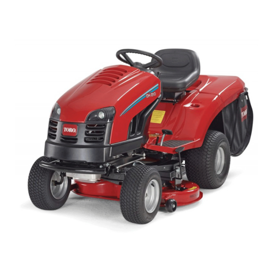
- Page 1 Form No. 3360-462 Rev C DH 220 Lawn Tractor Model No. 74592—Serial No. 280000001 and Up Register at www.Toro.com. Original Instructions (EN)
-
Page 2: Introduction
Whenever you need service, genuine Toro parts, or additional information, contact an Authorized Service Dealer or Toro Customer Service and have the model and serial numbers of your product ready. Figure 1 identifies the location of the model and serial numbers on the product. -
Page 3: Table Of Contents
Safe Operation Practices for Riding Rotary Checking the Tire Pressure ......... 31 Lawn Mowers........... 4 Servicing the Brake..........31 Toro Riding Mower Safety ........5 Belt Maintenance............ 32 Sound Pressure............. 5 Adjusting the Blade Drive Belt ......32 Sound Power ............5 Servicing the Grass Collector........ -
Page 4: Safety
Preparation Safety • While mowing, always wear substantial footwear and long trousers. Do not operate the equipment when Safe Operation Practices for barefoot or wearing open sandals. Riding Rotary Lawn Mowers • Thoroughly inspect the area where the equipment is to be used and remove all objects which may be Read and understand the contents of this manual before thrown by the machine. -
Page 5: Toro Riding Mower Safety
• Disengage drive to attachments, stop the engine, The following paragraph contains safety information and disconnect the spark plug wire(s) or remove the specific to Toro products that is not included in the ignition key CEN standard. – before clearing blockages or unclogging chute;... -
Page 6: Vibration
Vibration This unit does not exceed a hand/arm vibration level of 1.6 m/s2, based on measurements of identical machines per EN 836 and EN 1033. This unit does not exceed a whole body vibration level of 1.6 m/s2, based on measurements of identical machines per EN 836 and EN 1032. -
Page 7: Slope Chart
Slope Chart... -
Page 8: Safety And Instructional Decals
Safety and Instructional Decals Safety decals and instructions are easily visible to the operator and are located near any area of potential danger. Replace any decal that is damaged or lost. Manufacturer’s Mark 1. Indicates the blade is identified as a part from the original machine manufacturer. - Page 9 104-2903 1. Warning, tipping 4. Cutting/dismemberment hazard—do not drive hazard of hand or foot, across slopes greater than mower blade—disconnect 5 degrees, down slopes the spark plug wire and greater than 15 degrees, read the instructions 104-3233 or up slopes greater than before servicing or 10 degrees.
- Page 10 104-3239 and 104-3240 1. Height of cut 3. Increase 2. Decrease 104-3234 1. Fast 5. Headlights 2. Continuous variable 6. On setting 104-3241 3. Slow 7. Engine—start 4. Engine—stop 1. Forward 4. Slow 2. Continuous variable speed 5. Fast 3. Neutral 6.
-
Page 11: Product Overview
Product Overview Operation Note: Determine the left and right sides of the Controls machine from the normal operating position. Become familiar with the controls (Figure 3) before you start the engine and operate the machine. Adding Fuel Use unleaded regular gasoline suitable for automotive use (85 pump octane minimum). -
Page 12: Using Stabilizer/Conditioner
• It cleans the engine while it runs • It eliminates gum-like varnish buildup in the fuel In certain conditions, gasoline is extremely system, which causes hard starting flammable and highly explosive. A fire or Important: Do not use fuel additives containing explosion from gasoline can burn you and methanol or ethanol. -
Page 13: Positioning The Seat
Hour Meter Note: The parking brake lever should release. 2. Gradually release the brake pedal. The hour meter is located on the instrument panel (Figure 3) and shows the total operating hours of the machine. Positioning the Seat The seat can move forward and backward. Position the Using the Blade Control (PTO) seat where you have the best control of the machine The blade control (PTO) knob engages and disengages... -
Page 14: Setting The Height Of Cut
Disengaging the Blades 1. Depress the brake pedal to stop the machine. 2. Push the blade control (PTO) knob into the Disengaged position (Figure 5). Setting the Height of Cut Use the height-of-cut lever to raise and lower the mower to the desired cutting height. -
Page 15: Stopping The Engine
5. When starting a cold engine, shift the throttle control lever to the Choke position (Figure 12). Figure 10 1. Fuel shut-off valve Figure 12 Note: The valve handle should align with the fuel 1. Throttle control lever 5. Lights hose. -
Page 16: Using The Safety Interlock System
the engine before you stop it. You may stop the stop. Do not mow in reverse unless it is absolutely engine in an emergency by turning the ignition key necessary. to Off. If you need to use the blades (PTO) while backing up, turn off the interlock feature using the KeyChoice Using the Safety Interlock switch located near the seat bracket (Figure 13). -
Page 17: Testing The Safety Interlock System
3. Turn the KeyChoice key. engine is running, release the parking brake and rise slightly from the seat: The engine should stop. A red light on the front console (Figure 14) turns on, indicating that the interlock is disabled. 4. Shift the blade control (PTO) knob into the Disengage position, put the traction control pedal in Neutral, and start the engine. -
Page 18: Driving The Machine Forward Or Backward
Figure 16 1. Traction control pedal 2. Reverse speed pedal Figure 15 Note: To increase the speed, push the traction 1. Operate position 2. Push position control pedal down. To decrease the speed, release the pressure on the traction control pedal. To Operate the Machine To go backward: 1. -
Page 19: Using The Bag On Demand
Children or bystanders may be injured if they move or attempt to operate the machine while it is unattended. Always remove the ignition and KeyChoice keys and set the parking brake when leaving the machine unattended, even if it is just for a few minutes. -
Page 20: Operating Tips
Operating Tips • For the best performance, operate the engine at the maximum speed. The mower requires air to thoroughly cut grass clippings, so do not set the height-of-cut too low or completely surround the mower in uncut grass. Always leave one side of the mower free from uncut grass to allow the air to be drawn into the mower. -
Page 21: Maintenance
Maintenance Note: Determine the left and right sides of the machine from the normal operating position. Recommended Maintenance Schedule(s) Maintenance Service Maintenance Procedure Interval • Change the engine oil. After the first 5 hours • Check the blade drive belt adjustment. After the first 25 hours •... -
Page 22: Lubrication
Lubrication Greasing and Lubricating the Machine Service Interval: Every 25 hours/Yearly (whichever comes first)—Grease and lubricate the machine. (Grease and lubricate it more frequently when operating it in dusty or sandy conditions.) How to Grease the Machine Grease the machine with a general-purpose grease. 1. -
Page 23: Where To Add Grease
Where to Add Grease Figure 19 Item Name Quantity Interval (hours) Lubricant (pumps) Front wheel—grease fittings Grease Steering ball joints Steering sector gear Grease Steering pinion gear Grease Steering shaft bearing Steering shaft bearing Motion lever—grease fitting Grease Shaft hub for lifting the mower housing Motion link ball joints Brake pedal hubs Parking brake ring... -
Page 24: Servicing The Engine Oil
Removing the Foam and Paper 1. Wash the foam element in liquid soap and warm Elements water and rinse it thoroughly. 2. Dry the element by squeezing it in a clean cloth. 1. Clean around the air cleaner to prevent dirt from getting into the engine and causing damage. - Page 25 12. Stop the engine and wait for 30 seconds. 13. Check the oil level again and add oil if necessary. Important: Do not overfill the crankcase with engine oil and run the engine; engine damage may result. Changing the Engine Oil Service Interval: After the first 5 hours Every 50 hours (Change the engine oil more frequently when operating...
-
Page 26: Servicing The Spark Plug
Changing the Engine Oil Filter Service Interval: Every 100 hours 1. Drain the oil from the engine; refer to Changing the Engine Oil. 2. Remove the old filter and wipe off the adapter gasket surface (Figure 25). Figure 26 1. Spark plug wire 7. -
Page 27: Fuel System Maintenance
Fuel System 8. Pull the fuel line off the fuel filter (Figure 28) and allow the gasoline to drain into an approved fuel Maintenance container or a drain pan. Note: Now is the best time to install a new fuel Draining the Fuel Tank filter because the fuel tank is empty. -
Page 28: Electrical System Maintenance
Electrical System Maintenance Replacing the Fuse The electrical system is protected by fuses. They are located beneath the hood, near the fuel tank (Figure 30). If a fuse goes out, check the circuit wiring for a short. Figure 31 1. Bulb holder 4. -
Page 29: Servicing The Battery
Servicing the Battery Always keep the battery clean and fully charged. Use a paper towel to clean the battery and battery box. If the battery terminals are corroded, clean them with a solution of 4 parts water and 1 part baking soda. Apply a light coating of grease to the battery terminals to prevent them from corroding. - Page 30 Important: Do not overfill the battery. (Figure 33). Slide the rubber cover over the battery post. Electrolyte (sulfuric acid) can severely corrode and damage the chassis. Checking the Electrolyte Level 4. Replace the filler caps. Service Interval: Before each use or daily Charging the Battery 1.
-
Page 31: Drive System Maintenance
Checking the Brake Drive System Service Interval: Before each use or daily Maintenance 1. Park the machine on a level surface. 2. Disengage the blades (PTO). Checking the Tire Pressure 3. Set the parking brake. Service Interval: Every 25 hours/Yearly (whichever 4. -
Page 32: Belt Maintenance
Belt Maintenance Servicing the Grass Collector Adjusting the Blade Drive Belt Removing the Grass Collector Service Interval: After the first 25 hours—Check the blade drive belt adjustment. 1. Use 2 hands to tip the grass collector forward (Figure 38). Every 50 hours—Adjust the blade drive belt. -
Page 33: Mower Deck Maintenance
Mower Deck 8. Ensure that the bag on demand is in the bagging mode and clean the inside of the tunnel all the way Maintenance to the mower. 9. Install the grass collector; refer to Installing the Servicing the Blades Grass Collector. -
Page 34: Removing The Mower
Important: If the shear pins are broken, the mower 2. Position the blades 90 degrees to each other belt may be damaged. Inspect the belt; refer to (Figure 42). Adjusting the Blade Drive Belt. Removing the Blades 1. Remove the mower; refer to Removing the Mower. 2. -
Page 35: Installing The Mower
Adjusting the Height Adjustment Cable Rod Assembly Service Interval: Every 100 hours/Yearly (whichever comes first)—Check the front-to-rear blade slope. (Also check it whenever you install the mower.) Before you check the slope, inflate the front and rear tires to the recommended air pressure; refer to Checking the Tire Pressure. -
Page 36: Storage
Storage F. Start and run the engine until it will not start again. 1. Disengage the blades (PTO). G. Recycle the old fuel according to local codes. 2. Set the parking brake. H. Close the fuel shut-off valve. 3. Stop the engine and wait for all moving parts to stop. Important: Do not store stabilizer/conditioned gasoline over 90 days. -
Page 37: Troubleshooting
Troubleshooting Problem Possible Cause Corrective Action The starter does not crank. 1. The blade control (PTO) knob is 1. Move the blade control (PTO) knob to engaged. the Disengaged position. 2. The parking brake is not on. 2. Set the parking brake. 3. - Page 38 Problem Possible Cause Corrective Action There is abnormal vibration. 1. The blades are bent or unbalanced. 1. Install a new blades. 2. The blade mounting screws are loose. 2. Tighten the blade mounting screws. 3. The engine mounting bolts are loose. 3.
- Page 39 Spypros Stavrinides Limited Cyprus 357 22 434131 Surge Systems India Limited India 91 1 292299901 T-Markt Logistics Ltd Hungary 36 26 525 500 Toro Australia Australia 61 3 9580 7355 Toro Europe BVBA Belgium 32 14 562 960 374-0102 Rev B...
- Page 40 Contact your seller to arrange service of the product. If for any reason materials or workmanship. The following time periods apply from the date it is impossible for you to contact your seller, you may contact any Toro of original purchase: Authorized Distributor to arrange service.