
Related Manuals for Bosch Rexroth Hagglunds CBm


Summary of Contents for Bosch Rexroth Hagglunds CBm
- Page 1 Installation & Maintenance manual Hägglunds CBm Radial piston hydraulic motor RE 15300-WA, Version: 06.2021, Replaces: 07.2019, EN...
- Page 2 © This document, as well as the data, speci- fications and other information set forth in it, are the exclusive property of Bosch Rexroth AG. It may not be reproduced or given to third parties without its consent.
-
Page 3: Table Of Contents
Installation conditions .................22 7.2.1 Spline shaft end ..................22 7.2.2 Plain shaft end ....................22 Required tools .....................23 7.3.1 Assembly tool for coupling adapter .............23 7.3.2 Tool for spline alignment ................24 7.3.3 Assembly tool for motor ................26 RE 15300-WA, Version 06.2021, Bosch Rexroth AB... - Page 4 11.4 Preparing the components for storage or further use ........68 Disposal ....................69 12.1 Environmental protection ................69 Extension and conversion ................ 69 Troubleshooting ..................70 Technical data ..................71 15.1 Technical data, Hägglunds CBm ..............71 15.1.1 Hydraulic fluids ...................71 Bosch Rexroth AB, RE 15300-WA, Version 06.2021...
-
Page 5: This Documentation
Consistent safety instructions, symbols, terms and abbreviations are used in the present documentation to facilitate orientation for the reader and to ensure safe product handling. The explanations in the following sections will provide for easy understanding RE 15300-WA, Version 06.2021, Bosch Rexroth AB... -
Page 6: Symbols
▶ Single, independent step Numbered instructions: The number indicates that the different steps are to be performed successively. Center of gravity Markings on packaging to indicate where the center of gravitiy is. Bosch Rexroth AB, RE 15300-WA, Version 06.2021... -
Page 7: Safety Instructions
• Modification of factory settings by non-authorized persons • Use of add-on parts (e.g. mountable filter, control unit, valves) that are not specified by Bosch Rexroth has to be approved by contact at Bosch Rexroth. RE 15300-WA, Version 06.2021, Bosch Rexroth AB... -
Page 8: Personnel Qualifications
• fully understanding in particular the interrelationships regarding safety devices and having knowledge on the function and assembly of hydraulic components. Bosch Rexroth offers training support for special fields. For more information about training, please contact your Bosch Rexroth representative. -
Page 9: Product-Specific Safety Instructions
▶ Do not disconnect any line connections, ports and components when the machine/system is pressurized. ▶ Switch off all power-transmitting components and connections (electric, pneumatic, hydraulic, mechanical) in accordance with the manufacturer‘s instruction and secure them against being switched back on. RE 15300-WA, Version 06.2021, Bosch Rexroth AB... -
Page 10: Personal Protection Equipment
2.7 Personal protective equipment (PPE) PPE is the responsibility of the user of the Hägglunds motors. Observe the safety regulations and provisions of your country. All components of the PPE must be intact. Bosch Rexroth AB, RE 15300-WA, Version 06.2021... -
Page 11: General Instructions On Material Damage And Product Damage
▶ Do not perform any electro-welding at all on the driven machine with a flange mounted motor without providing some special grounding to avoid any current going through the hydraulic motor. ▶ Remove any sensitive electronic equipment before performing any electro- welding on the machine. RE 15300-WA, Version 06.2021, Bosch Rexroth AB... - Page 12 The warranty applies only to the delivered configuration. The entitlement to warranty cover will be rendered void if the product is incorrectly installed, commissioned or operated, or if it is used or handled improperly. Bosch Rexroth AB, RE 15300-WA, Version 06.2021...
-
Page 13: About This Product
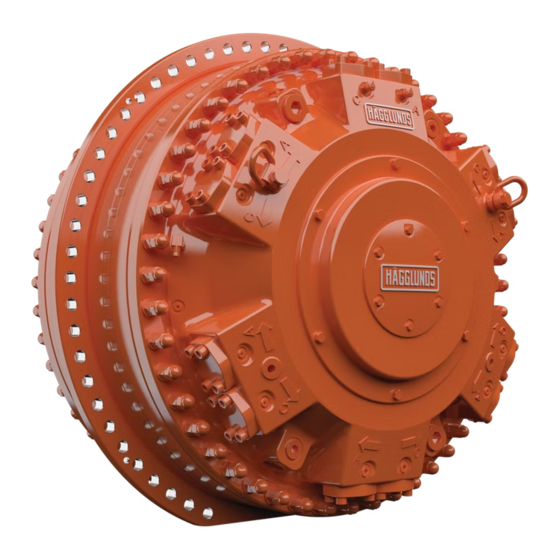
Connection side 7 Cylindrical roller bearing of the motor of the motor 8 Housing cover 9 Wear ring 10 Distributor 11 Connection housning 12 Product identification DD00093357 Fig. 1: The CBm radial piston motor RE 15300-WA, Version 06.2021, Bosch Rexroth AB... -
Page 14: Product Identification
14/72 Scope of delivery About this procuct 5.3 Product identification DD00083926 1 Type of product 2 Serial number 3 Weight 4 Manufacturer 5 Max pressure Fig. 2: Plate on motor Bosch Rexroth AB, RE 15300-WA, Version 06.2021... -
Page 15: Transport And Storage
27.17 in — — — — Table 5: Tightening torque for lifting eyes Screw dimension Number of screws Tightening torque Motor type Ibf⋅ft CBm 2000 to CBm 4000 CBm 5000 to CBm 6000 RE 15300-WA, Version 06.2021, Bosch Rexroth AB... -
Page 16: Lifting Motors And Accessories
CBm 5000 to CBm 6000 Fig. 5: Lifting motor with shaft in vertical plane DD0000059039 DD00059023 CBm 2000 to CBm 4000 CBm 5000 to CBm 6000 Fig. 6: Lifting motor with shaft in horizontal plane Bosch Rexroth AB, RE 15300-WA, Version 06.2021... - Page 17 CBm 2000 to CBm 4000 Fig. 7: Lifting motor and mounted single ended torque arm DD00060023 DD00060009 CBm 2000 to CBm 4000 CBm 5000to CBm 6000 Fig. 8: Lifting motor and mounted double ended torque arm RE 15300-WA, Version 06.2021, Bosch Rexroth AB...
- Page 18 Transport and storage DD00046324 DD00058278 Fig. 9: Lifting single ended torque arm Fig. 10: Lifting Coupling adapter DD00046325 CBm 2000 Tandem kit CBp 400 Fig. 11: Lifting CBm 2000 in tandem with CBp 400 Bosch Rexroth AB, RE 15300-WA, Version 06.2021...
-
Page 19: Product Storage
It is also advisable to provide supports shown in Fig. 12. A) Standing with B) Standing with shaft horizontal shaft vertical Support DD00046331 Fig. 12: CBm motor standing on a flat surface RE 15300-WA, Version 06.2021, Bosch Rexroth AB... -
Page 20: Storing For Extended Periods Or In Uncontrolled Environment
Fig. 13: Filling the motor with oil Table 6: Motor case oil volume Motor size Motor case oil volume including channels Litre US gallon CBm 2000 19.8 CBm 3000 24.0 CBm 4000 28.2 CBm 5000 32.4 CBm 6000 36.4 Bosch Rexroth AB, RE 15300-WA, Version 06.2021... -
Page 21: Storing During Maintenance
3 Remove the packaging from the Hägglunds motor. 4 Check the Hägglunds motor for transport damage and completeness, see chapter 4: Scope of delivery. 5 Dispose of the packaging according to the environmental regulations of your country. RE 15300-WA, Version 06.2021, Bosch Rexroth AB... -
Page 22: Installation Conditions
For further information see data sheet RE 15300 Bosch Rexroth AB, RE 15300-WA, Version 06.2021... -
Page 23: Required Tools
Coupling adapter: Assembly tool for coupling adapter: 1 Lifting eye 6 Nut 2 Dismounting tool 7 Carriage beam 3 Screws 8 Adapter M30 to M20 (included in 4 Adapter shaft delivery) 5 Shrink disc RE 15300-WA, Version 06.2021, Bosch Rexroth AB... -
Page 24: Tool For Spline Alignment
Material ID Spline alignment tool: Material ID R939061395 DD00077430 Fig. 15: Spline align tool 1 Spline align tool 2 Bar (Not included) 3 Assembly tool R939003866 (not included) Bosch Rexroth AB, RE 15300-WA, Version 06.2021... - Page 25 Step 1 to 3 above in reverse order to remove the tool. Tightening torque according to Fig. 16. DD00060093 Mv 80 Nm [59 lbf·ft] Mv 200 Nm [148 lbf·ft] Fig. 16: Mounting the spline alignment tool RE 15300-WA, Version 06.2021, Bosch Rexroth AB...
-
Page 26: Assembly Tool For Motor
Assembly tool motor 1 Tie rod 2 Washer 3 Nut 4 Dismantle tool and screws (used for motor removal) Fig. 17: Mounting CBm motor with assembly tool Bosch Rexroth AB, RE 15300-WA, Version 06.2021... -
Page 27: Product Installation
6. Tighten the screws (1) to the torque stated in Table 7: Screw dimensions. DD00047783 Fig. 18: Mounting single ended torque arm TC A 2000 and TC A 4000 for CBm 2000 to CBm 4000 RE 15300-WA, Version 06.2021, Bosch Rexroth AB... - Page 28 CBm 3000 to CBm 4000 M30x90 10.9 57 1840 1357 DTCBM 1600 to 4000 CBm 2000 to CBm 4000 M30x90 10.9 57 1840 1357 DTCBM 4600 to 6000 CBm 5000 to CBm 6000 M30x90 10.9 114 1840 1357 Bosch Rexroth AB, RE 15300-WA, Version 06.2021...
-
Page 29: Single Ended Torque Arm Installation
Table 8: Dimensions torque arm TC A Torque arm Motor type Weight TC A 2000 CBM 2000 2 000 78.74 22.83 CBM 3000 to CBm TC A 4000 3 000 118.11 27.17 1 929 4000 RE 15300-WA, Version 06.2021, Bosch Rexroth AB... - Page 30 150-175°C, gases are emitted that can cause serious health risk. If hot work (e.g. welding) is done on the product, protective breathing equipment must be used. ▶ Never use motor as grounding point. Bosch Rexroth AB, RE 15300-WA, Version 06.2021...
- Page 31 69 241.15 251 553 56 551.36 TC A 4000 CBM 4000 4000 560 000 125 893.00 495 705 111 438.90 The force Fr is calculated including the weight of motor and torque arm. RE 15300-WA, Version 06.2021, Bosch Rexroth AB...
- Page 32 Fig. 27: Electrical isolated articulated connection TC A Description Description Linkage part Bearing cover Fastening support Split pin Bolt Washer (electrical isolated) Supporting disc Bushing (electrical isolated) Spherical plain bearing Washer (electrical isolated) Countersunk head screw Bosch Rexroth AB, RE 15300-WA, Version 06.2021...
-
Page 33: Double Ended Torque Arm Installation
DTCBM 2600 electrical isolated 3 200 125.98 1 874 1 558 1 149.12 DTCBM 3600 electrical isolated 3 600 141.73 2 094 DTCBM 4000 electrical isolated 4 200 165.35 1 130 2 491 RE 15300-WA, Version 06.2021, Bosch Rexroth AB... - Page 34 Table 11: Hole pattern dimensions for articulated connection and hydraulic cylinder DTCBM 1600 to DTCBM 4000 Torque arm DTCBM 1600 to 4000 9.17 6.22 9.06 23.86 1.50 DTCBM 1600 to 4000 9.65 6.65 9.06 11.81 1.50 electrical isolated Bosch Rexroth AB, RE 15300-WA, Version 06.2021...
- Page 35 143 023.40 114 590 25 760.86 DTCBM 6000 17 CBM 6000 6000 646 400 159 726.80 82 527 18 552.81 The force Fr is calculated included the weight of spline motor and torque arm. RE 15300-WA, Version 06.2021, Bosch Rexroth AB...
- Page 36 Fig. 34: Articulated connection and hydraulic cylinder for DTCBM 1600 to DTCBM 4000 Description Tightening torque Articulated connection Shaft Circlips Hydraulic cylinder Air bleeding G ¼" Attachment brackets Screw M36-8.8 2280 Nm / 1681 lbf ft 8 (Not included in delivery) Bosch Rexroth AB, RE 15300-WA, Version 06.2021...
- Page 37 Table 13: Hole pattern dimensions for articulated connection and hydraulic cylinder DTCBM 4600 to DTCBM 6000 Torque arm DTCBM 4600 to 6000 9.17 10.27 4.72 25.59 1.50 (Articulated connection) DTCBM 4600 to 6000 9.17 6.22 9.06 23.86 1.50 (Hydraulic cylinder) RE 15300-WA, Version 06.2021, Bosch Rexroth AB...
- Page 38 Air bleeding G ¼“ Attachment brackets Screw M36-8.8 2280 Nm / 1681 lbf ft 18 (Not included in delivery) Fastening Spherical plain bearing Washer Shaft Fastening Bearing cover Split pin Countersunk head screw Bosch Rexroth AB, RE 15300-WA, Version 06.2021...
- Page 39 ▶ Make sure to follow the installation instructions regarding hydraulic connections . The cylinders should be vented from air during commisioning by using the air bleeding screws on the cylinder, see Fig. 34 and Fig. 37 RE 15300-WA, Version 06.2021, Bosch Rexroth AB...
-
Page 40: Mounting Of Motor And Shrink Disc Adapter
If nescesary separate the clamping ring for easier mounting. 7. Absolutely no grease on the surfaces between driven shaft and hollow shaft. Clean the driven shaft and the inside of the hollow shaft Bosch Rexroth AB, RE 15300-WA, Version 06.2021... - Page 41 When a motor has been in for overhaul or service and shall be reassembled it may be necessary to relubricate those surfaces with Molykote G-Rapid plus paste again but remember only the specified surfaces. RE 15300-WA, Version 06.2021, Bosch Rexroth AB...
- Page 42 8. Remove the lifting device and the lifting eyes from the coupling adapter. DD00058276, DD00080049 Driven shaft Coupling adapter Assembly tool 1 Nut 2 Carriage beam Fig. 41: Mounting the coupling adapter on the driven shaft with the assembly tool. Bosch Rexroth AB, RE 15300-WA, Version 06.2021...
- Page 43 Ø 340 mm CBm 2000 8.46 Ø 360 mm CBm 2000 to CBm 3000 10,12 Ø 460 mm CBm 3000 to CBm 4000 11,81 Ø 480 mm CBm 5000 to CBm 6000 12,60 RE 15300-WA, Version 06.2021, Bosch Rexroth AB...
- Page 44 9. When the specified torque is reached it is important that all screws are tightened with specified torque and that no further movement can be observed. DD00079284 Keep the coupling adapter or coupling motor in level with driven shaft! Fig. 44: Gap between the clamping rings Bosch Rexroth AB, RE 15300-WA, Version 06.2021...
- Page 45 ▶ There is a metallic sign on every shrink disc with a tightening torque stamped on it. This torque is always to be used. ▶ Tightening torque value is critical. Use calibrated torque wrench. ▶ Uncoated screws shall be greased with Molykote G-Rapid plus paste. RE 15300-WA, Version 06.2021, Bosch Rexroth AB...
- Page 46 G ¼ connection on shaft side seal retainer, see Fig. 49. Torque the G ¼ plugs. Torque 30 Nm (22 lbf ft.) 14. Remount the cover (1). Torque 200 Nm (148 lbf·ft). Bosch Rexroth AB, RE 15300-WA, Version 06.2021...
- Page 47 4. Mounting kit 1. Cover (delivered with motor) Oil filling of spline Spacer Spacer Screw, 5. Screw M30 Axial clearance 10 mm Fig. 47: Fix the spline motor with the mounting kit, horizontal mounting RE 15300-WA, Version 06.2021, Bosch Rexroth AB...
- Page 48 (Dismantling tool and screws, not used at mounting!) Driven shaft Key grip 3. Bearing holder 1. Cover 2. Plug G 1¼ 4. Harsh kit Fig. 48: Mounting of coupling motor with assembly tool Bosch Rexroth AB, RE 15300-WA, Version 06.2021...
- Page 49 DD00080051 8. Plug G ¼ Oil filling of spline 8. Plug G ¼ 5. Screw M30 7. Plug G ¼ Fig. 49: Vertical mounting of spline motor RE 15300-WA, Version 06.2021, Bosch Rexroth AB...
- Page 50 M16x50 8.8 Mv 197Nm Tightening the shrink disc according to : Tightening of shrink disc page 44 Fig. 51: Vertical mounting of motor with special index coupling adapter AS XXXX B 1 006 Bosch Rexroth AB, RE 15300-WA, Version 06.2021...
-
Page 51: Flange Mounting Of Motor
If oil here, it can be used Plug G 1¼ for the spline. Then take away the o-ring. D D 0 0 0 5 8 2 2 1 Fig. 52: Flange mounted motor, shaft horizontal RE 15300-WA, Version 06.2021, Bosch Rexroth AB... -
Page 52: Draining And Venting The Motor
With bidirectional drives, use the connection with lowest average pressure. (Connection to high pressure will increase the motor drain flow). It is advisable to fit the adapter and the hose to the motor before fitting the torque arm. Bosch Rexroth AB, RE 15300-WA, Version 06.2021... -
Page 53: Flushing
RE 15300 or contact your Bosch Rexroth representative. The flushing oil shall be drained in the normal drainline, see chapter 7.4.6: Draining and venting the motor. Connect the input flushing line at the lowest drain port, D1-D8 at opposite side compared to the drain outlet in order to obtain a cross flushing flow through the motor, see Fig. -
Page 54: Port Connections
DD00058251 Rotation flow inlet Rotation flow inlet C1 - C6 A1 - A6 Fig. 55: Connection side of the motor DD00058253 Fig. 56: Shaft side of the motor Bosch Rexroth AB, RE 15300-WA, Version 06.2021... - Page 55 Magnetic plug 1 1/16-12-UN-2B Used to monitor impurities in the oil. Alternative magnetic T7, T9 1 1/16-12-UN-2B Normally plugged at delivery. plug connection *SAE flange J 518 , code 62, 420 bar (6000 psi). RE 15300-WA, Version 06.2021, Bosch Rexroth AB...
-
Page 56: Direction Of Rotation Of Motor Shaft
▶ Do not touch rotating parts or be in the zone of rotating parts. DD00057404 Rotating part Fig. 57: Rotating part, motor with coupling adapter Rotating part Rotating part DD00094551 DD00057380 Fig. 58: Rotating part coupling motor and spline motor Bosch Rexroth AB, RE 15300-WA, Version 06.2021... - Page 57 With the inlet flow supply connected to C port, the motor shaft rotates clockwise viewed from the shaft side of the motor. RE 15300-WA, Version 06.2021, Bosch Rexroth AB...
-
Page 58: Commissioning
2. Check the drain line to ensure that excessive pressure does not build up in the motor case; see chapter 7.2: Installation conditions and: 7.4.6: Draining and venting the motor 3. Check that the motor is protected from overloads, see chapter Motor data in data sheet 15300. Bosch Rexroth AB, RE 15300-WA, Version 06.2021... -
Page 59: Start Of The Hydraulic Supply
In case of accident or malfunction where it is not possible to determine the status of the Hägglunds product, please contact your Bosch Rexroth representative. 9 Operation The product is a component wich requires no settings or changes during operation. -
Page 60: Maintenance And Repair
10.2.1 Magnetic plug inspection A magnetic plug is installed in the drain connection. By regulary inspecting the magnetic plug a malfunction of the hydraulic system can be detected and Insert corrected. Fig. 60: Magnetic plug Bosch Rexroth AB, RE 15300-WA, Version 06.2021... -
Page 61: Oil Inspection
• If more or larger visible particles are found on the magnet than normal, reduce the checking interval to every second day to determine the trend of the particle level. Please contact your Bosch Rexroth representative for further actions. 10.2.2 Oil inspection Purpose to take oil sample The purpose to take an oil sample is to check the condition of the oil. - Page 62 Clean the coupling and the hose carefully. Connect the hoses according to the particle counters manual. To get a true value the contamination readings have to be stable about 10 min before you stop to measure. Bosch Rexroth AB, RE 15300-WA, Version 06.2021...
-
Page 63: Maintenance Plan
Torque arm Magnetic plug After the first 100 hours After 3 months or 500 hours Once every 2 weeks Once every 6 months Once every 12 months R = Replacement, I = Inspection RE 15300-WA, Version 06.2021, Bosch Rexroth AB... -
Page 64: Maintenance
Degree of contamination Heavy contamination of the oil causes increased wear of the components in hydraulic system. The cause of the contamination must be immediatly investigated and remedied. Bosch Rexroth AB, RE 15300-WA, Version 06.2021... -
Page 65: Repair
Repairs on the Hägglunds products may only be performed by service centers certified by Bosch Rexroth. ▶ Use exclusively original spare parts from Bosch Rexroth to repair the Hägglunds products, otherwise the functional reliability of the products can not be assured and you loose your entitlement under warranty. -
Page 66: Removing Motor And Coupling Adapter
▶ Use an oil binding agent if hydraulic fluid is spilled. ▶ Observe the information in the safety data sheet for the hydraulic fluid and the specifications provided by the system manufacturer. Bosch Rexroth AB, RE 15300-WA, Version 06.2021... - Page 67 8. Untighten the screws on the shrink disc gradually, appr. a quarter turn each. Keep doing this until all screws are untighten. 9. Pull the motor off the shaft by turning the nut on the assembly tool. RE 15300-WA, Version 06.2021, Bosch Rexroth AB...
-
Page 68: Preparing The Components For Storage Or Further Use
4 Nut and washer 5 Carriage beam Fig. 62: Assembly tool for removing the coupling adapter 11.4 Preparing the components for storage or further use Proceed as described in chapter 6.2: Product storage. Bosch Rexroth AB, RE 15300-WA, Version 06.2021... -
Page 69: Disposal
- Steel - Aluminum - Non-ferrous metal - Electronic waste - Plastic - Seals 13 Extension and conversion Do not modify Hägglunds products. Please contact your Bosch Rexroth representative for extension or conversion. RE 15300-WA, Version 06.2021, Bosch Rexroth AB... -
Page 70: Troubleshooting
70/72 Troubleshooting 14 Troubleshooting Please, contact your nearest Bosch Rexroth representative. Table 20: Troubleshooting hydraulic motor Fault Probable cause Action Mechanical stop in the drive. Check system pressure. If the pressure has risen to the relief valve setting, remove the load from the drive. -
Page 71: Technical Data
RE 15300 , chapter Recommended charge pressure ▶ Changes to the factory settings must only be made by Bosch Rexroth specialist personnel. 15.1.1 Hydraulic fluids The hydraulic CBm motor is primarily designed for operation with hydraulic fluids according to ISO 11158 HM. - Page 72 Bosch Rexroth AB SE-895 80 Mellansel Sweden Tel. +46 (0) 660 870 00 Fax +46 (0) 660 871 60 hagglunds@boschrexroth.com Your local contact can be found at: www.hagglunds.com We reserve the right to make changes Printed in Sweden RE 15300-WA, 06.2021...